New lift EAZ-TFT User manual

Position indicator
MANUAL

Manuak EAZ-TFT
Manufacturer NEW LIFT Neue elektronische Wege
Steuerungsbau GmbH
Lochhamer Schlag 8
82166 Gräfelng
Tel +49 89 – 898 66 – 0
Fax +49 89 – 898 66 – 300
Mail [email protected]
www.newlift.de
Service line Tel +49 89 – 898 66 – 110
Mail [email protected]
Date of issue 14.03.2011
Author KH
Last Change 04.12.2020 AME
Release 04.12.2020 AL
Hardware version 0.2
Software version 1.3.0
Doc. No. hb_EAZT-TFT_2020-09_en
Copyright © NEW LIFT Steuerungsbau GmbH, 2020.
This manual is protected by copyright. All rights, including those of copying,
of reproduction, of translation and of modication, in whole or in part, are
reserved by the publisher.
No part of this description may be reproduced in any form or copied with an
electronic replication system without written permission.
Although great care has been taken in the production of texts and gures, we
cannot be held legally liable for possible mistakes and their consequences.

Manuak EAZ-TFT 3
Contents
1 General 4
1.1 Abbreviations, characters and symbols used 4
1.2 Notation 4
1.3 Further information 5
1.4 How to contact us 5
2 Safety 6
2.1 General safety regulations 6
2.1.1 Applicable standards and guidelines 6
2.1.2 Electromagnetic compatibility (EMC) 6
2.1.3 Handling electronic assemblies 6
3 EAZ-TFT 7
3.1 Technical data 7
3.2 Terminalassignmentandconguration 7
3.2.1 Connections 7
3.2.2 Jumpers 8
3.2.3 CongurationsviatheFSTcontrolsystem 9
3.3 Uploading the software update 10
4 EAZDesigner 11
4.1 Requirements 11
4.2 Installation 11
4.3 Work areas 11
4.3.1 Menu bar 11
4.3.2 Preview area 11
4.3.3 Display area 12
4.3.4 Backgroundarea 19
4.4 Gettingstarted 19
General
4Manuak EAZ-TFT
1 General
The EAZ-TFT position indicators were developed specically for the FST control system from NEW
LIFT. The high-quality TFT display has full graphic capability and can be used in the car and landing call
panel. The EAZDesigner software lets you customise your displays right down to the smallest detail.
The colour spectrum includes more than 262000 colours.
1.1 Abbreviations, characters and symbols used
Symbol /
abbreviation Meaning
EAZ position indicators
Delivery condition
Settings that are supplied as standard are marked with an asterisk .
►Operational instructions
Perform the tasks that follow this symbol in the specied order.
Warning notice
This symbol is located in front of safety-relevant information
Information notice
This symbol is located in front of relevant information.
1.2 Notation
Notation Meaning
Bold ›Designations of switches and actuators
›Input values
Italics ›Captions
›Cross references
›Designations of functions and signals
›Product names
Bold italics ›Remarks
LCD font ›System messages of the controller

General
Manuak EAZ-TFT 5
1.3 Further information
The following documents, among others, are available for the FST control system and its components:
›FST Installation & Commissioning
›FST manual
›ADM manual
›FPM manual
›SAM manual
›EAZ-256 manual
›EAZ-LCD and EAZ-VFD manual
›Fire recall manual
These and other current manuals can be found in the download area of our website at
https://www.newlift.de/downloads-311.html
1.4 How to contact us
If, after referring to this manual, you still require assistance, our service line is there for you:
Phone +49 89 – 898 66 – 110
E-mail [email protected]
Mon. - Thurs.: 8:00 a.m. – 12:00 p.m. and 1:00 p.m. – 5:00 p.m.
Fr: 8:00 a.m. – 3:00 p.m.

Safety
6Manuak EAZ-TFT
2 Safety
2.1 General safety regulations
The EAZ-256 position indicators must only be operated in perfect working condition in a proper
manner, safely and in compliance with the instructions, the valid accident prevention regulations and
the guidelines of the local power company.
The safety guidelines of the FST manual and the FST Installation and Commissioning manual always apply.
2.1.1 Applicable standards and guidelines
All EAZ-256 position indicators comply with:
›the safety guidelines for the construction and installation of passenger and goods passenger lifts (DIN
EN 81 Part 1 and 2).
›the conditions for the erection of high voltage installations with nominal voltages up to 1 kV (DIN VDE
0100).
›the contact protection measures in the machine room (VDE 0106).
›the data sheet on safety measures for the installation, maintenance and commissioning of lift systems
(ZH 1/312).
2.1.2 Electromagnetic compatibility (EMC)
An accredited inspection authority has inspected the FST control system and its components in
accordance with the standards, thresholds and severity levels named in EN 12015/1995 and EN
12016/1995.
The FST control system and its components are:
›immune to electrostatic discharge (EN 61000-4-2/1995)
›immune to electrostatic elds (EN 61000-4-3/1997)
›immune to fast transient disturbances (EN 61000-4-4/1995)
The electromagnetic disturbance eld strengths created by the FST control system and its components
do not exceed the permissible thresholds. (EN 55011/1997).
2.1.3 Handling electronic assemblies
›Keep the electronic assembly in its original packaging until installation.
›Before opening the original packaging, a static discharge must be performed. To do this, touch a
grounded piece of metal.
›During work on electronic assemblies, periodically perform this discharge procedure.
›All bus inputs and outputs not in use must be equipped with a terminal resistor (terminator).

EAZ-TFT
Manuak EAZ-TFT 7
3 EAZ-TFT
The EAZ-TFT can be used as a car and landing display. The installation takes place in the corresponding
car and landing call panels.
3.1 Technical data
Description Value
Supply voltage 24 V DC ±10%
Typical power consumption < 300 mA
Outputs Short circuit-proof
Length x height x depth 146 x 140 x 40 (+2) mm
Bolts M4 x 8mm
Preview window aperture 117.2x88.4mm
Temperature range: Storage & transport / operation -20 – +70 °C / ±0 – +60 °C
Relative humidity: Storage & transport / operation
(non-condensing)
+5 – +95 % / +15 – +85 %
JS
X1
X2
X5
SD-Card
JK1
JK2
JK3
JT1
JT2
JHV
JCF
140
126
146
10
7
EAZ-TFT circuit board marking
See appendix for more details.
3.2 Terminalassignmentandconguration
3.2.1 Connections
LON bus
The position indicator is connected to the LON bus via sockets X1 and X2.
SD slot
The SD memory card is inserted into the SD X5 slot.
EAZ-TFT
8Manuak EAZ-TFT
3.2.2 Jumpers
The service jumper JS is not plugged in.
Jumper J1 – J3: FST assignment
FST assignment JK1 JK2 JK3
FST A open open open
FST B plugged open open
FST C open plugged open
FST D plugged plugged open
FST E open open plugged
FST F plugged open plugged
FST G open plugged plugged
FST H plugged plugged plugged
Jumper JT1: Door side
Installation position TI
Door side A open
Door side B plugged
Jumper JT2
No function yet.
Jumper JVH: Installation position
Installation position VH
Horizontal open
Vertical (currently not supported) plugged
Jumper JCF: Installation site
Installation site CF
Landing open
Car plugged

EAZ-TFT
Manuak EAZ-TFT 9
3.2.3 CongurationsviatheFSTcontrolsystem
The EAZ-TFT must be selected as the EAZ type before you can make settings via the FST
Setting the EAZ type
►Config / EAZ Configuration / LON-EAZ Type
►Set EAZ-TFT with £¢ and conrm with E
►Exit menu and save settings with ¥.
In addition to the jumper settings, the following settings can be made via the FST menu
Config->EAZ Configuration->LON-EAZ Config:
›Design selection: NEW LIFT provides 16 standard factory designs (0000 dddd)
›Languages: German, English
Setting design and language
►Config / EAZ Configuration / LON-EAZ Config
►Select the individual digits with ¥¤and set the respective digit with £¢ and conrm with E
►Exit menu and save settings with ¥.

EAZ-TFT
10 Manuak EAZ-TFT
The settings are made according to the following bit pattern. The designs (for an overview, see „Fig.
Overview of standard designs with associated bit patterns“ are set according to their valence via bit 0 - 3. The
language is set via bit 7.
Overview of standard designs with associated bit patterns
S 0 0 0 D D D D
11 22 44 88
Bit 0 - 3: Standard Designs
Bit 7: Sprachauswahl: 0 = Deutsch; 1 = Englisch
Bit pattern for settings of the EAZ-TFT in the FST menu
3.3 Uploading the software update
►Unzip the Update_Vxxx.zip le and copy the directory update to the existing SD card.
There must be at least one EAZ design on the SD card!!
►Reinsert the SD card into the EAZ-TFT and restart the EAZ-TFT.
The update will run after the boot screen. It takes about 1-5 minutes. Do not switch off the EAZ during
this time.
The EAZ automatically restarts following the successful update. The software version is then updated
in the boot screen.

EAZDesigner
Manuak EAZ-TFT 11
4 EAZDesigner
NEW LIFT has developed the user-friendly EAZ Designer specically for the EAZ-TFT. With its graphical
Windows interface, the EAZDesigner enables the simple, customised design of the EAZ-TFT.
4.1 Requirements
PC operating system: XP, Vista or Windows 7 Microsoft .NET Framework 3.5 or higher
PC equipment: Internal or external SD card reader
4.2 Installation
Simply follow the instructions of the installation manager. If you have not yet installed Microsoft .NET
Framework on your PC, the latest version of .NET should automatically begin to download.
4.3 Work areas
4.3.1 Menu bar
›New: Opens new project
›Open: Opens the project folder of the EAZDesigner. This is how to open existing projects.
›Save as: Opens the window to save the current project
›Save: Saves the current project
›Create display output: Opens the window to select the SD card as the storage medium for a nished
project
›Format SD card: Formats the SD card
›Language: Language selection
4.3.2 Preview area
All created projects, including the standard designs, can be displayed in the preview area.
For an overview of the standard design, please select the green „standard“ area in the drop-down eld.
NEW LIFT currently offers 16 standard designs that can be used free of charge.

EAZDesigner
12 Manuak EAZ-TFT
Selection of the standard designs in the EAZDesigner
Opening an existing design
►Select the design and click the open button.
►The program automatically switches to the display area.
4.3.3 Display area
In the display area, you can determine all the settings of your position indicator except for the
background.
1Floor name
Two-digit letter and number combination
2Floor text
Additional text for each individual oor
3Directional arrows and departure arrows (only full image)
Can be placed left, right, above or below the oor text.

EAZDesigner
Manuak EAZ-TFT 13
4Event texts
If desired, the date and time are displayed in this area during normal operation. Only when an event is
output by the control system (e.g. re recall) does the corresponding event appear in this area.
You can place the individual display elements using the dotted lines that are always shown as soon as
you have opened the display layout menu.
The setting options include the following sub-items
Display layout
The basic orientation and rough positioning of the individual display elements are implemented via the
display layout.
Settings options for the display layout
Installation position
►Determine whether the direction of the display is horizontal or vertical under Installation position
Floor text
In addition to the oor names (G, B, 1st, etc.), individual oor texts can be added to the oors (lobby,
parking garage, ladies department, etc.). The oor text appears below the oor name. It is associated
with the oor and must therefore be entered for each oor.
►Activate the Floor text checkbox
ªThe list of setting options now also shows the item „Floor text“
Background image
All common image les (JPG, TIFF, PNG) can be used as a background. If it is a picture or other graphic,
the shadowing and 3D effects are omitted from the oor names and arrows.
►Activate the Photo background checkbox
If it is a logo that is placed on a solid-coloured background next to the display elements, all functions
are available and the photo background checkbox does not have to be activated.
Positioning the display elements
The position and size of the individual elements can be changed by using the mouse on the dotted lines.
This is how to make the rst rough settings. Fine adjustments can be made later via the corresponding
setting points.

EAZDesigner
14 Manuak EAZ-TFT
Floor name
Floor names are adopted from the FST by default. Optical adjustments can be made here as follows.
Setting options for oor names
Positioningtheoorname
The position of the oor name depends on the selected alignment (align left, centre, right) and the
borders (left, top, right)
►Orientation: In the drop-down menu, select between align left, centre and right to align the oor
name
►Borders: Change the values left, top, right to nely adjust the positioning of the oor name
Fixed digit width
Because digits have different tracking depending on the font, this can lead to an uneven number
continuation when running through the oors. A xed width can be set for all digits in order to avoid
this.
►Activate the xed digit width checkbox
Fonts
A number of fonts are available in the drop-down menu. Depending on the font family, additional font
styles can be selected (regular, bold, extra bold)
Colour settings
The characters can also be customised by borders or colour lling. You can choose between various
widths, colours and effects.

EAZDesigner
Manuak EAZ-TFT 15
Floortexts(ifunderoortextdisplaylayout)
Floor texts are texts that are displayed in addition to the oor name (e.g. lobby, parking garage, ladies
department, etc.). These texts must be entered individually for each oor.
If the oor text eld is not visible, activate the oor text checkbox in the display layout eld
Setting options for oor texts
Creatingoortexts
►Use the + and - oor buttons to set the desired floor number
►Complete the oor text for the respective oor in the oor text eld (line breaks are added with ; )
►If desired, change the font, style, size, colour and border
To check the settings, either click on the respective oor text or on the Auto animation oor text
button in the demo window below the display.
Forcedoorname
You can replace or supplement the default oor names output by the FST using a forced oor name
that you have dened.
►Activate the Short description instead of FST text checkbox
►Enter a short description (up to 5 digits) to replace the text output by the FST or enter a 2-digit text
and ** (placeholder for FST text) to supplement the FST text (e.g. **FL: Output of the oors as 1st FL,
2nd FL, etc.)
Numbering: The lowest oor corresponds to oor 0.

EAZDesigner
16 Manuak EAZ-TFT
Arrow style
The form and colour of all arrow types can be customised independently of each other.
Setting options for arrow styles
Arrow type
►Activate the Editable down arrow checkbox if you want to design the up and down arrows
differently
►Click on the desired arrow to set its position, form and colour settings
Position
►Select an arrow position from the drop-down menu (left, top, bottom, right)
Fillings & borders
►Use the Filling method drop-down menu to determine whether the arrow is to be displayed
proportionally or to t the area
►Make the ne adjustments to the borders in the numeric elds
Colour settings
The characters can also be customised by borders or colour lling. You can choose between various
widths, colours and effects.

EAZDesigner
Manuak EAZ-TFT 17
Event texts
For events, the EAZDesigner provides a list with preset event texts (all can be changed and expanded).
If none of the events are active, the date and time output by the FST can be displayed if desired.
Additional informational text can be displayed with each event text. Here the event and informational
text are displayed alternately. The informational text can also be used as a translation in order to
alternately display German / English.
Setting options for event texts
Event texts
►Customise the event texts via the Text1;Info1 and Text2;Info2 elds
►Customise the font and background colour as well as the font family and style using the text settings
►Position the oor text using the position/length bar
Informational texts
►Add the desired informational text directly after the event text and separate them with a ;
Example: Emergency stop;Please remain calm
►Activate the Flashing text function so that the text and information are displayed alternately
To check the settings, either click on the respective event or on the Auto-Animation events button in
the demo window below the display. The cursor in the Preview partial text indicates which of the event
columns (Text1, Info1, Text2 or Info2) is currently being displayed in the preview
Date & time
Under Date/time you can choose whether you want to display this information during normal
operation
►From the drop-down eld, choose the format for the date and
►make ne adjustments to the position using the elds date left, date at top, time left, time at top
►If desired, change the spelling of the name of the month (remember that you may have to reduce the
font size)
EAZDesigner
18 Manuak EAZ-TFT
Graphics
Corresponding symbols can be displayed in addition to the event notications. NEW LIFT offers a
graphics library to be used free of charge. However, you can also embed custom symbols in png format.
The graphics can be displayed as a small icon next to the text or as a full image above the event text.
►Activate the Use symbol checkbox and select a graphic using the ... button
►With the Full image checkbox, determine whether the symbol is to be placed as a small icon next to
the event text or as a full image above the event text
►With the Shadow checkbox, determine whether the symbol should have a shadow effect
►Set the desired size using the Size bar and position the graphic using the Position bar
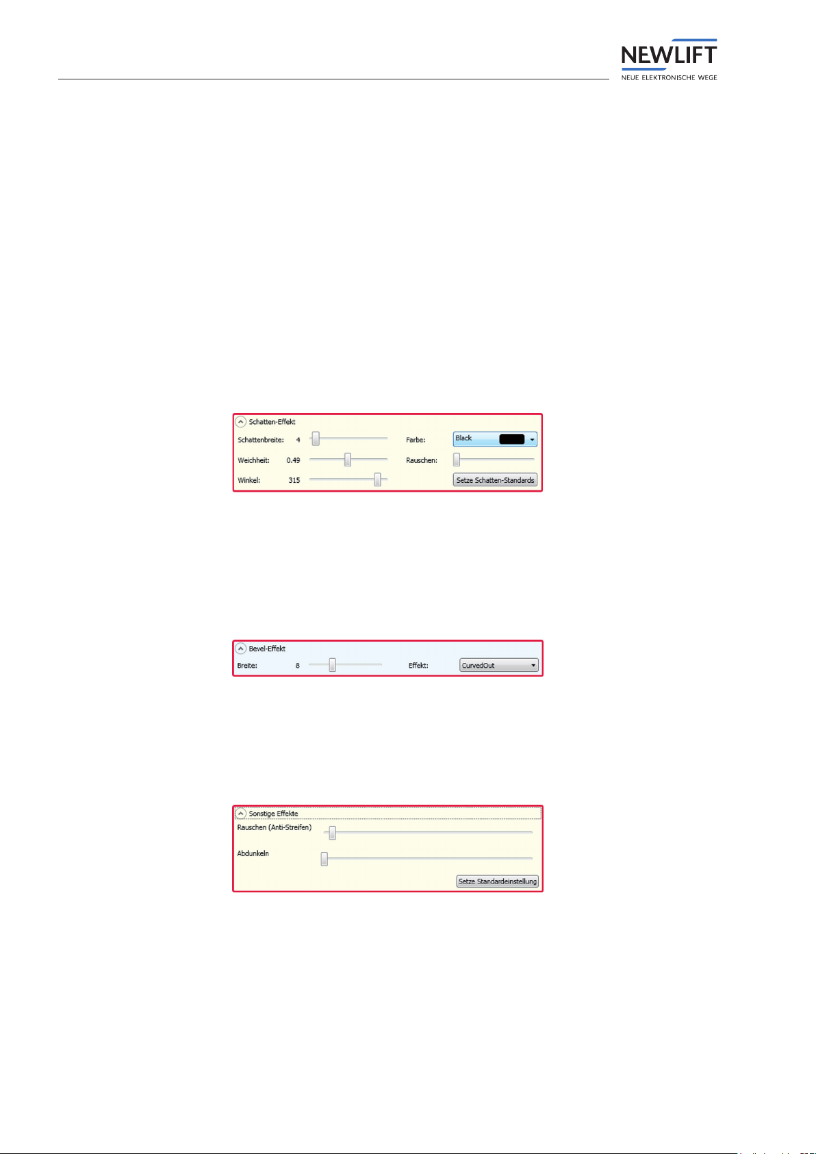
Shadow effect
To give the display elements a 3-dimensional appearance, you can add shadowing. Here you can change
the shadow width, softness, angle, colour and random noise. All settings can also be reset using the set
Shadow standards button.
Setting options for shadow effect
Relief effect
The so-called relief effect can provide oor names and arrows with different reliefs. You can decide
between the various widths and natures of the effect.
Setting options for oor name
Other Effects
Using this window you can increase the random noise of the display or darken it.
Setting options for other effects
Demo window
›You will see a window with several auto-animation buttons below the preview. Here you can view oor
names, oor texts and events as auto-animations.

EAZDesigner
Manuak EAZ-TFT 19
4.3.4 Background area
Setting options for the background
Here you can make all of the settings for the background of your position indicator.
If you would like a background image for your position indicator, you can upload this into the program
using the Upload image button.
You can, of course, use background colours and gradients instead of a background image.
4.4 Getting started
Here are some procedural tips if you would like to create your personal position indicator.
›First choose a background (e.g. le with your company logo) in order to be sure that you can later place
the display elements accordingly.
›Now open the display layout eld and leave this open during the entire design process. You can change
the position of the individual elements at any time by using the dotted lines.
›In the display layout eld, choose whether you would like to display extended oor texts and determine
whether you are using a plain background or a photo/other image le.
›Open the arrow layout eld and make sure that the ‚editable down arrow‘ checkbox is deactivated
(an activated checkbox is only necessary if you want different up and down arrows. If this is the case,
please only activate the checkbox after completing the editing and then make the individual settings
for the down or departure arrow).
Now determine whether the arrows are to be placed to the left, right, top, or bottom of the oor text
›Finally, you can move the dotted lines using the drag and drop function and can thus change the
position of the display elements.
Tip: If you want to set the arrows above or below the oor texts or want to display extended oor texts,
you must rst move the dotted lines before these settings will be visible
›If you have roughly determined the position of the display elements, you can still make ne adjustments
to the position, colour, fonts, etc. in the respective eld.

20 Manuak EAZ-TFT
140,0mm
126,0mm
88,4mm
44,2mm 44,2mm
146,0mm
126,0mm
117,2mm
58,6mm 58,6mm
4x 5,0mm
4x Kunststoff Abstandsbolzen mit beidseitigem
M4 Innengewinde und 23,0mm Länge
2,0 mm
23,0mm
42,0mm
±0,1
Alle Toleranzen 0,2mm sofern nicht anders angegeben!±
This manual suits for next models
4
Table of contents
Other New lift Measuring Instrument manuals


Popular Measuring Instrument manuals by other brands


Tektronix
Tektronix IsoVu TIVP Series user manual

Cyfral
Cyfral VIDEOMONITOR V4 Operating, Installation and Programming Manual

Effigis
Effigis CPAT FLEX Operation manual

Keysight Technologies
Keysight Technologies E4981A Service guide

APL
APL SEM 3P V2 Technical manual

Interacoustics
Interacoustics Luna Service manual


