New lift A6 PL 0 10 2.2 User manual

Manual
A6
Safety Monitoring Device
PL 0 10 2.2

A6_EN.DE05/01
Publisher NEW LIFT Steuerungsbau GmbH
Lochhamer Schlag 8
D- 82166 Gräfelfing
Germany
Tel.: +49 (0) 89 / 8 98 66 - 0
Fax: +49 (0) 89 / 8 98 66 - 3 00
Doc. No. A6_BA.EN05/01
Date of issue 05/01
Copyright © 1999, NEW LIFT Steuerungsbau GmbH
All rights including those of copying and reproduction of parts of this de-
scription and of the translation are reserved by the publisher.
No part of this description may be reproduced in any form or copied with an
electronic replication system without the written permission of the publish-
er.

Contents
A6_BA.EN05/01 3
1 About this Manual ...............................................................................................5
1.1 General........................................................................................................................... 5
1.2 Signs and symbols used........................................................................................ 6
2 General Safety Regulations..........................................................................7
2.1 Intended use................................................................................................................ 7
2.2 Safety regulations......................................................................................................7
3 Important Facts about your A6 Safety Monitoring Device.....9
3.1 Working principle...................................................................................................... 9
3.2 LEDs and terminals................................................................................................ 10
3.3 Dimensions and technical data......................................................................... 12
4 Installation and Commissioning............................................................. 15
4.1 Mounting and Wiring the A6 Safety Monitoring Device........................... 16
Mounting the A6 Safety Monitoring Device ..................................................................... 16
Wiring the A6 Safety Monitoring Device.......................................................................... 16
4.2 Commissioning the A6 Safety Monitoring Device..................................... 17
5 Troubleshooting and Servicing............................................................... 19
5.1 Troubleshooting....................................................................................................... 19
5.2 Servicing..................................................................................................................... 19
6 Declarations of Conformity......................................................................... 21

Contents
4A6_BA.EN05/01

1 About this manual
A6_BA.EN05/01 5
1 About this manual
Please read this manual carefully before installing, commissioning or ser-
vicing the A6Safety Monitoring Device. Alsosee chapter 2 „General Safety
Regulations“.
1.1 General
This manualcontains important information forsafe and properinstallation,
commissioning and servicing of the A6 Safety Monitoring Device.
Following these instructions will help to:
- prevent danger
- avoid repair costs and standstill
- increase the reliability and lifespan of the A6 Safety Monitoring Device
and the lift system.
Local, national and on-site regulations regarding health and safety and pro-
tection of the environment must be taken into account in addition to this
manual.
This manual only describes the NEW LIFT A6 Safety Monitoring Device of
the lift system.
One copy of this manual must be given to the engineer when installing and
commissioning the A6 Safety Monitoring Device. It must be placed in the
controller cabinet after commissioning.The factory test logs of the A6 Safe-
ty circuit remain with NEW LIFT.
Please refer to the respective manufacturer’s or supplier’s documentation
for information about all other components of your lift system.
1 About this manual
6A6_BA.EN05/01
1.2 Signs and symbols used
The following signs and symbols are used:
Symbol
Activity Symbol:
Activities described after this symbol must be carried out in the given or-
der.
Warning sign High voltage
This sign marks activities with danger of electric shock with pos-
sibly fatal consequences.

2 General Safety Regulations
A6_BA.EN05/01 7
2 General Safety Regulations
All important safety regulations are summarized in this chapter.
All persons performing installation, commissioning or servicing work
on the A6 Safety Monitoring Device must read this chapter and follow
its regulations.
All installation, commissioning or servicing work on the A6 Safety Monitor-
ing Device must be performed by or supervised by a qualified electrician.
A qualified electrician has appropriate training and knowledge of regula-
tions that allow him to judge the quality of the work performed and spot pos-
sible dangers.
Laws, regulations, guidelines and standards that apply in the country of op-
eration must be followed in addition to the safety regulations mentioned in
this manual.
2.1 Intended Use
The A6 Safety Monitoring Device according to EN 81-1/-2, 14.1.2.3 and
TRA 264.2 is only intended for use as a control element in hydraulic and
cable lifts to enable the following functions of the lift:
- Landing andrelevelling the carwithopen carand shaftdoors (according
to EN 81-1/81-2, 14.2.1.2 and TRA 265.1).
- Ramp control (according to EN81-1, 14.2.1.5 / EN81-2, 14.2.1.4 and
TRA 266.3)
The A6 Safety Monitoring Device is used to override the door and locking
switches (safety switches) in the unlocking zone.
2.2 Safety Regulations
General The instructions of the lift manufacturer and the instructions in this manual
must be followed during installation, commissioning and servicing of the lift
system.
Alcohol and drugs must not be consumed before and during installation
and commissioning.

2 General Safety Regulations
8A6_BA.EN05/01
Electricity Danger to life! Do not touch live parts while working on electrical equip-
ment.
Regulations for installing and operating electrical equipment (VDE 0100)
and regulations of local utilities must be followed.
The specified distances between different electrical assemblies must be
controlled and maintained.
All installation work must be carried out with the system shut down and off
circuit.
All cables and wires must be installed with sufficient strain relief.
Working in the shaft When using the car for an assembly platform, regulations from VGB 35
“Building hoists” apply for the entire lift system.
Troubleshooting and
Servicing The A6 Safety Monitoring Device must not be tampered with or repaired.
A faulty A6 Safety Monitoring Device must be replaced. The replaced A6
Safety Monitoring Device must be returned to NEW LIFT for quality control
and documentation.
Waste Disposal Faulty parts that cannot be repaired must be disposed of in an environmen-
tally acceptable manner in accordance with the governing environment
protection laws. Separate the different materials (plastic, metal, electronic
components) and recycle them.

3 Important Facts about your A6 Safety Monitoring Device
A6_BA.EN05/01 9
3 Important Facts about your A6 Safety Monitoring
Device
The A6 Safety Monitoring Device according to EN 81-1/-2, 14.1.2.3 and
TRA 264.2 is only intended for use as a control element in hydraulic and
cable lifts to enable the following functions of the lift:
- Landing andrelevelling the carwithopen carand shaftdoors (according
to EN 81-1/81-2, 14.2.1.2 and TRA 265.1).
- Ramp control (according to EN81-1, 14.2.1.5 / EN81-2, 14.2.1.4 and
TRA 266.3)
The A6 Safety Monitoring Device is used to override the door and locking
switches (safety switches) in the unlocking zone.
A type verification certificate from the German TÜV and an EC Declaration
of Conformity are available (see “Declarations of Conformity” on page 21).
3.1 Working Principle
Abb. 3.1 Diagram of working principle
lift controller A6 Safety Monitoring Device
+24V,GND power supply
door zone enable
+24V
door zone signal
override
safety circuit
error signalshut down
sensor A
sensor B
GND
external
error signal
A6002.cdr

3 Important Facts about your A6 Safety Monitoring Device
10 A6_BA.EN05/01
The A6 Safety Monitoring Device is a stand-alone relay circuit to override
the door andlocking switches in the unlocking zone of the shaft doors. The
car position is continuously monitored with two non-equivalent sensors
(magnet switches on the car).
If the controller enables the zone circuit (while landing on a level or during
adjustment) and the car is in the unlocking zone (sensor A closed, sensor
B open), the A6 Safety Monitoring Device sends a zone signal to the con-
troller and closes the contacts to override the door and locking switches.
If the car leaves the unlocking zone or the controller does not enable the
zone circuit, the zone signal and the door and locking switch override are
deactivated.
If the position ofsensor A and sensor B is not non-equivalent for more than
1 second, the lift controller system is shut down by the issuing of an error
signal. The shut down lift can only be reactivated by cycling the lift control-
ler system OFF and ON.
3.2 LEDs and Terminals
Abb. 3.2 LEDs and terminals of the A6 Safety Monitoring Device
A6003.cdr
Sicherheitsschaltung
A6
Zonenfehler
Zonenmeldung
K202
K201
K200
24V DC
PL 0 10 2.2
505
506
507
508
509
510
511
512
513
514
515
516
517
518
519
501
502
503
504
NEW

3 Important Facts about your A6 Safety Monitoring Device
A6_BA.EN05/01 11
LEDs
Terminals
LED Col-
our State Description
Zonenfehler red on Sensor A/B not non-equivalent
or A6 SafetyMonitoring Device
faulty
Zonenmel-
dung green on Sensor A closed
Sensor B open
24V DC green on Power supply
K202 red on out of zone
K201 red on out of zone
K200 green on in zone
A6 Description
501 Error signal for shutting down the system (input)
502 Error signal for shutting down the system (output)
503 Override door locking equipment (input)
504 Override door locking equipment (output)
505 External error signal (isolated input)
506 External error signal (isolated output)
507 Zone signal (isolated input)
508 Zone signal (isolated output)
509 NC
510 GND emergency power supply
511 + 6 - 24 V emergency power supply
512 + zone indicator EN81-2, 12.9.3 and TRA 228.5
513 - zone indicator EN81-2, 12.9.3 and TRA 228.5
514 Zone enable (input + 24 V DC)
515 Sensor B
516 Sensor A
517 GND
518 GND (power supply)
519 + 24 V DC (power supply)

3 Important Facts about your A6 Safety Monitoring Device
12 A6_BA.EN05/01
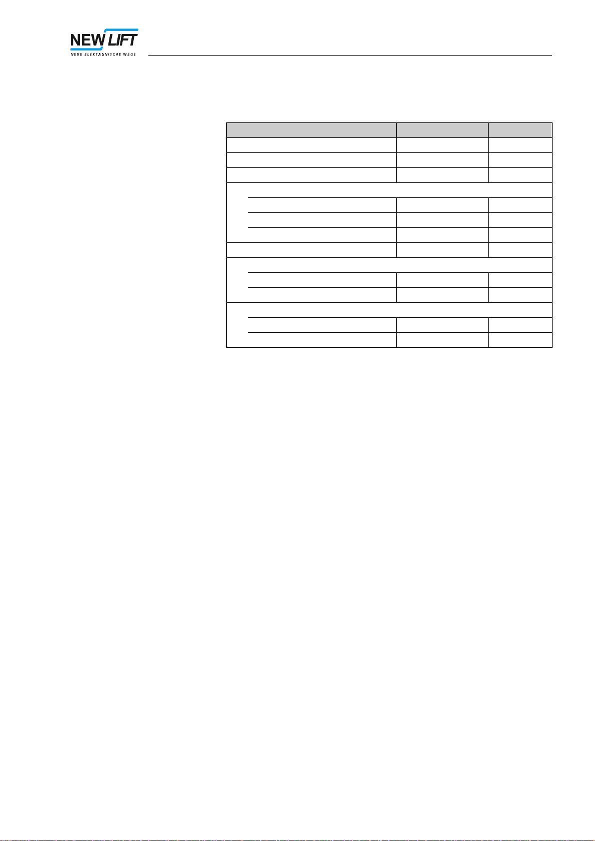
3.3 Dimensions and Technical Data
Dimensions
Abb. 3.3 Dimensions of the A6 Safety Monitoring Device
A6004.cdr
top-hat rail mounting lock
3 Important Facts about your A6 Safety Monitoring Device
A6_BA.EN05/01 13
Technical data Description Value Unit
Signal voltage 24 ±10% V DC
Power consumption 200 mA
Fusing the safety circuit C2
Output limits
Voltage 250 V
Current 4 A
Capacity 800 VA
Length x width x height 100 x 75 x 110 mm
Temperature range
Storage / transport -20 - +70 °C
Operation ±0 - +60 °C
Relative humidity
Storage / transport 5 - 95 %
Operation 15 - 85 %

3 Important Facts about your A6 Safety Monitoring Device
14 A6_BA.EN05/01
Notes

4 Installation and Commissioning
A6_BA.EN05/01 15
4 Installation and Commissioning
All important information for installing and commissioning the A6 Safety
Monitoring Device is described in this section. On-site circumstances may
require a different order of assembly than the one suggested here.
If the A6 Safety Monitoring Device is part of a lift controller system supplied
by NEW LIFT, it is delivered in the wired controller cabinet and installation
is to be carried out following the instructions of your lift controller.
Abb. 4.1 Recommended order of installation and commissioning of
the A6 Safety Monitoring Device.
Mounting the
A6 Safety Monitoring Device
A6005.cdr
Wiring the
A6 Safety Monitoring Device
Mounting the
magnet swichtes sensor A/B
Connecting the
magnet swichtes sensor A/B
to the A6 Safety Monitoring
Device
Commissioning the
the lift controller and
the A6 Safety Monitoring
Device
Operating test of the
A6 Safety Monitoring Device
4 Installation and Commissioning
16 A6_BA.EN05/01
4.1 Mounting and Wiring the A6 Safety Monitoring Device
The A6 Safety Monitoring Device must be mounted in a controller cabinet
rated as IP54 and fused with C2 (safety circuit) and 0.5 A (+ 24 V DC).
Control engineering regulations according to VDE 0100 must be fol-
lowed when mounting and wiring the A6 Safety Monitoring Device in
the controller cabinet.
Mounting the A6 Safety Monitoring Device
The A6 Safety Monitoring Device is snapped onto a top-hat rail DIN EN
50022 in the controller cabinet or fastened to the supporting plate with two
screws. (See fig. “Dimensions of the A6 Safety Monitoring Device” on page
12.)
Wiring the A6 Safety Monitoring Device
The A6 Safety Monitoring Device is wired according to the documentation
of the lift controller used.
All signal voltage wires must be at least 0,5 mm2and all wires of the safety
circuit (501, 502, 503, 504) at least 1,0 mm2.
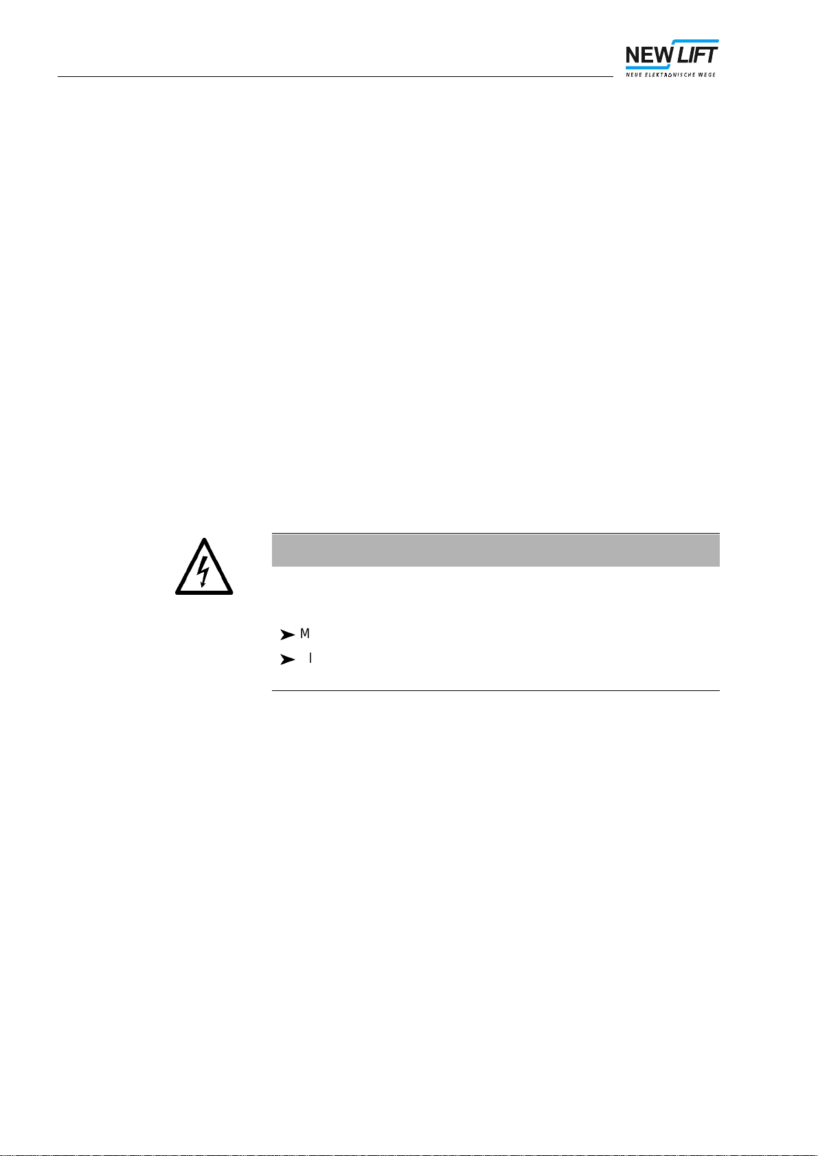
WARNING!
Electric hazard due to live wires and parts.
Death or serious injury.
Make sure system is off circuit.
All installation work on electrical parts must be carried out with the
system shut down and off circuit.

4 Installation and Commissioning
A6_BA.EN05/01 17
4.2 Commissioning the A6 Safety Monitoring Device
The shaft components are connected to the A6 Safety Monitoring Device
according to the instructions of the controller manufacturer after installing
the controller cabinet in the machine room.
With NEW LIFT controls, the A6 Safety Monitoring Device is always mount-
ed and wired in the controller cabinet.
Requirements - Safety circuit in operation
- Control in operation
- Awareness of all possible dangers in the shaft and how to avoid them.
- Installation and wiring of the A6 Safety Monitoring Device and sensors
A and B completed.
Sensor switching points The sensor switching points must be adjusted so that in the zone area sen-
sor A is closed and sensor B open. The zone area is ±0,2 m (±0,35 m) from
the levelling position with symmetrical switching points.
Commissioning The A6 Safety Monitoring Device must be commissioned together with the
lift controller system used. The commissioning instructions of your control-
ler manufacturer will give you more information.
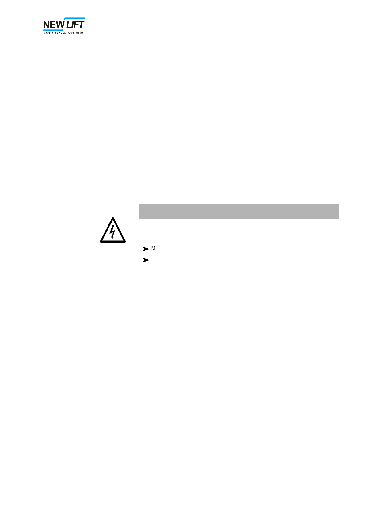
WARNING!
Electric hazard due to live wires and parts.
Death or serious injury.
Make sure system is off circuit.
All installation work on electrical parts must be carried out with the
system shut down and off circuit.

4 Installation and Commissioning
18 A6_BA.EN05/01
Operating Test The following checks must be carried out:
- in the zone (car is at rest)
Disconnect terminal 516 (sensor A). The zone errorLEDmust illumi-
nate within 1 second maximum.
- while the car is moving
Disconnect terminal 515 (sensor B) while the car is still at rest, then
start moving the car. When leaving the zone area, the zone error
LED must illuminate within 1 second maximum and the car must
come to rest at the next stop.
5 Troubleshooting and Servicing
A6_BA.EN05/01 19
5 Troubleshooting and Servicing
5.1 Troubleshooting
An error signal is sent when faults occur with the A6 Safety Monitoring De-
vice or with sensors A and B.
Requirements for
trouble-free operation - Power supply (24 V ±10%) on terminals 518 and 519
- The controller has enabled the A6 Safety Monitoring Device
- Sensors A and B are non-equivalent.
Malfunctions
If all requirements for trouble-free operation are met and the A6 Safety
Monitoring Device is still malfunctioning, it must be replaced.
The replaced A6 Safety Monitoring Device must be returned to NEW
LIFT. The A6 Safety Monitoring Device must not be opened or re-
paired.
5.2 Servicing
An operating test of the A6 Safety Monitoring Device (see page 18) is rec-
ommended when routinely servicing the lift system.
Other than that the A6 Safety Monitoring Device requires no servicing.
WARNING!
Electric hazard due to live wires and parts.
Death or serious injury.
Make sure system is off circuit.
All installation work on electrical parts must be carried out with the
system shut down and off circuit.

5 Troubleshooting and Servicing
20 A6_BA.EN05/01
Notes
Table of contents
Other New lift Measuring Instrument manuals


Popular Measuring Instrument manuals by other brands

Megger
Megger DLRO100EB manual

CGOLDENWALL
CGOLDENWALL NDJ-5S user manual

Horiba Scientific
Horiba Scientific LAQUA DS-71 Quick manual

Itm
Itm Oakton 450 Series Operation instructions

Tektronix
Tektronix TLA7S08 Declassification and security instructions

Agilent Technologies
Agilent Technologies OmniBER OTN Series Performance Verification Manual

Velleman
Velleman DEM400 user manual

Maxwell Digital Multimeters
Maxwell Digital Multimeters 25603 user manual

DEELAT
DEELAT D1140772 user manual

Endress+Hauser
Endress+Hauser Deltapilot S FMB70 Functional safety manual

Bender
Bender LIM2000-1NL quick start guide

York Survey Supply
York Survey Supply 343000 operating instructions


