New lift EAZ-TFT.45 User manual
TFT.45 - TFT.110 - TFT-210
Position indicators
MANUAL

Manual TFT Position indicators
Manufacturer NEW LIFT
Neue elektronische Wege
Steuerungsbau GmbH
Lochhamer Schlag 8
82166 Gräfelng
Tel +49 89 – 898 66 – 0
Fax +49 89 – 898 66 – 300
Mail [email protected]
www.newlift.de
Service line Tel +49 89 – 898 66 – 110
Mail [email protected]
First edition 31.01.2019
Author ASC / DOS
Last change 05.05.2020 / DOS
Release AL
Hardware version EAZ-TFT.45 : 5-78-20
EAZ-TFT.110/210 : 5-77-23
Softwarev ersion V1.010-0110
Doc. no. hb_eaztft.45-110-210_04-2020_V1.5_en
Copyright © NEW LIFT Steuerungsbau GmbH, 2020.
This manual is protected by copyright. All rights, including those of copying, of
reproduction, of translation and of modication, in whole or in part, are
reserved by
the publisher.
No part of this description may be reproduced in any form or copied with an
electronic replication system without written permission.
Although great care has been taken in the production of texts and gures, we
cannot be held legally liable for possible mistakes and their consequences..

Manual TFT Position indicators 3
Inhalt
1 Basic information 5
1.1 Abbreviations, characters and symbols used 5
1.2 Notation 6
1.3 Further information 6
1.4 How to contact us 6
2 Safety 7
2.1 Applicable standards and guidelines 7
2.2 Handling electronic assemblies 7
3 Technical data 8
3.1 General 8
3.2 Functional 8
3.3 Pin assignment 9
3.3.1 Terminal assignment – EAZ TFT.45 9
3.3.2 Terminal assignment – EAZ TFT.110 and TFT.210 10
3.3.3 I/O pin settings 14
3.3.4 Emergency functions 14
4 Installation and commissioning 15
4.1 Unpacking 15
4.2 Installation 15
4.2.1 Installation position 16
4.2.2 Installation dimensions – EAZ TFT.45 17
4.2.3 Installation dimensions – EAZ TFT.110 18
4.2.4 Installation dimensions – EAZ TFT.210 20
5 Menu 22
5.1 Starting menu 22
5.2 Menu structure 23
5.3 Start screen and main menu 24
5.3.1 Start screen – EAZ TFT.45 24
5.3.2 Start screen – EAZ TFT.110 and TFT.210 24
5.4 Navigation and operation 25
5.4.1 Navigation – EAZ TFT.45 25
5.4.2 Navigation – EAZ TFT.110 and TFT.210 25
5.4.3 Selecting menu item 26
5.4.4 Saving and rejecting settings 26
5.4.5 Conrmingandcancellingaction 26
5.4.6 Exiting main menu 27

4Manual TFT Position indicators
5.5 Submenus 28
5.5.1 Overview of submenus 28
5.5.2 Basic settings 29
5.5.3 Colour settings (OnBoard Designer) 31
5.5.4 Date settings (OnBoard Designer) 33
5.5.5 Status settings (OnBoard Designer) 34
5.5.6 Design transfer of internal designs (OnBoard designer) 35
5.5.7 USB services 37
6 Software update 42
6.1 TFT software update 42
6.2 Neuron update 44
Basic information
Abbreviations, characters and symbols used
Manual TFT Position indicators 5
1 Basic information
The position indicators of the series EAZ-TFT were developed specically for the FST control system
from NEW LIFT.
The displays can be used both in the interior panel and in the exterior panel and installed horizontally
or vertically.
All interfaces for lift call buttons, indicators, key switches, acoustic messages as well as exterior arrows
are on one module.
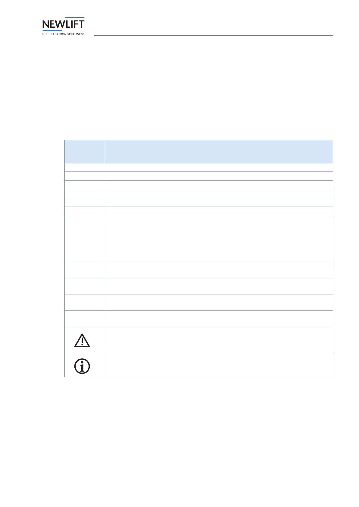
1.1 Abbreviations, characters and symbols used
Symbol/
abbrevia-
tion
Meaning
EAZ Position indicator
FST Field bus controller
ADM Landing call module
SAM Speech output module
FPM Car operating panel module
Menu Menu integrated in the TFT for editing display settings
OnBoard
designer
Designer integrated in the TFT for editing the onboard designs. The OnBoard Desi-
gner consists of four function groups:
›Colour setting
›Date display
›Status messages and
›Transfer
Custom
design Customer-specic design created using the EAZ Designer
OnBoard
design Standard design which can be edited on site using the OnBoard Designer
►Delivery condition
Settings that are supplied as standard are marked with an asterisk .
•Operational instructions
Perform the tasks that follow this symbol in the specied order.
Safety-relevant information
This symbol is located in front of safety-relevant information.
Information notice
This symbol is located in front of relevant information.

Basic information
Notation
6Manual TFT Position indicators
1.2 Notation
Displayed in bold are:
›Designations of menus, options, buttons, check boxes, input and display elds, display areas, navigation
areas, software functions
›Keyboard commands
Displayed in italics are:
›Designations of folders, screen windows, screen areas, work areas, tabs,
software dialogs
›Operating level, parameters, paths, operating modes, and input and display values
›Cross references
Displayed in the font LCD are:
›System messages of the FST
›Operating level, parameters, paths, operating modes, and input and display values of the FST menu.
Displayed in <italics in pointed brackets> are:
›Place holders for le names.
Symbol buttons are also used as designations in text as pictograms.
1.3 Further information
The following documents, among others, are available for the FST control system and its components:
›FST Installation & Commissioning Manual
›FST manual
›ADM manual
›EAZ-256 manual
›EN81-20 manual
›FPM manual
›Update-Backup-Analysis manual
›FST-2XT MRL manual
›GST-XT manual
›LCS manual
›RIO manual
›SAM manual
›UCM manual
These and other up to date manuals can be found in the download area of our website unter Service
http://www.newlift.en/service/download
1.4 How to contact us
Should you require support, our service line is there for you:
Tel +49 89 – 898 66 – 110
Mail [email protected]
Mon. - Thurs.: 8:00 a.m. – 12:00 p.m. and 1:00 p.m. – 5:00 p.m.
Fr: 8:00 a.m. – 3:00 p.m.
Safety
Applicable standards and guidelines
Manual TFT Position indicators 7
2 Safety
The position indicator may only be operated in perfect working condition in a proper manner, safely
and in compliance with the manual, the valid accident prevention regulations and the guidelines of the
local power company.
The safety guidelines of the FST manual and the FST Installation and Commissioning manual apply
for this product.
2.1 Applicable standards and guidelines
›DIN EN 81; Part 1 and 2:
Safety guidelines for the construction and installation of passenger and goods passenger lifts
›DIN VDE 0100:
Conditions for the erection of high voltage installations with nominal voltages up to 1 kV
›VDE 0106
Contact protection measures in the machine room.
›ZH 1/312 - BGI 779
Data sheet on safety measures for the installation, maintenance and repairs of lift systems
›EN 12015:2012
Electromagnetic compatibility – Product family standard for lifts, escalators and moving walkways –
Emitted interference
›EN 12016:2011
Electromagnetic compatibility – Product family standard for lifts, escalators and moving walkways –
Interference immunity
2.2 Handling electronic assemblies
Electrostatic charging
›Keep the electronic assembly in its original packaging until installation to prevent damage.
›Before opening the original packaging, a static discharge must be performed!
To do this, touch a grounded piece of metal.
›During work on electronic assemblies, periodically repeat this discharge procedure!
›Equip all bus inputs/outputs not in use with a terminal resistor (terminator) to prevent malfunctions.

Technical data
General
8Manual TFT Position indicators
3 Technical data
3.1 General
TFT 45 TFT 110 TFT 210
Dimensions 100mm x 55mm x 30mm 146mm x 106mm x
30mm
255mm x 180mm x
40mm
Display area (active
area) 45mm x 60mm 110 mm x 67 mm 211mm x 158mm
Resolution 240 x 320 800 x 480 800 x 600
Bits per pixel 18 24 24
Supply voltage 24 V DC ±10% 24 V DC ±10% 24 V DC ±10%
Typical power
consumption
120 mA (without button
acknowledgement)
150 mA (without button
acknowledgement)
400 mA (without button
acknowledgement)
Outputs Short circuit-proof Short circuit-proof Short circuit-proof
Weight 84 g 187 g 655 g
Max. output voltage
(ADM/FPM)
24 V DC 24 V DC 24 V DC
Max. output current
(ADM/FPM)
150 mA 150 mA 150 mA
Starting current 600 mA for approx. 40 ms 600 mA for approx. 40
ms
600 mA for approx. 40
ms
Temperature range:
Storage & transport /
operation
-20 – +70 °C / ±0 – +60 °C -20 – +70 °C / ±0 – +60
°C
-20 – +70 °C / ±0 – +60
°C
Relative humidity:
Storage & trans-
port / operation
(non-condensing)
+5 – +95 % / +15 – +85 % +5 – +95 % / +15 – +85 % +5 – +95 % / +15 – +85 %
3.2 Functional
Function TFT 45 TFT 110 TFT 210
Display 2.8 inch 5 inch 10.4 inch
Display screen Integrated Separate Separate
Installation orientation 0°, 90°, 180°, 270° 0°, 90°, 180°, 270° 0°, 90°, 180°, 270°
Prog. inputs/outputs 8 8 8
Prog. inputs 2 2 2
ADM/FPM
functionality YES YES YES
SAM functionality YES YES YES
Additional gong output NO YES YES
USB support MiniUSB USB, MiniUSB USB, MiniUSB
Emergency functions
- Please wait / Please
speak
- Emergency lighting
NO
NO
YES
YES
YES
YES
Design support
- Onboard design
- Custom design
YES
YES
YES
YES
YES
YES
- Application area Car/landing indicator Car/landing indicator
(can also be used as
a replacement for
EAZ-LCD/VFD)
Car/landing indicator
Technical data
Pin assignment
Manual TFT Position indicators 9
3.3 Pin assignment
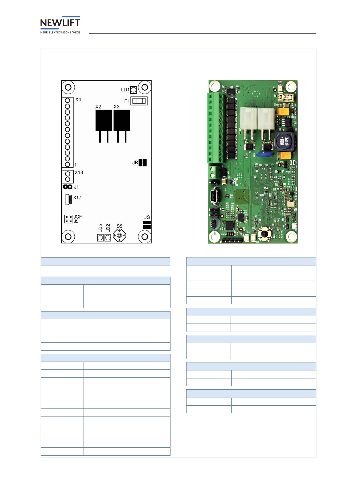
3.3.1 Terminal assignment – EAZ TFT.45
Schematic diagram – rear view
Fuse
F1 T 375 mA
LED
LD1 Fuse (red)
LD2 Service (yellow)
LD5 Power (green)
X2 / X3: LON / 24 volt supply
Pin 1 LON data A
Pin 2 LON data B
Pin 3 +24V
Pin 4 GND
X4: I/O pins
Pin 1 +24V
Pin 2 I/O
Pin 3 I/O
Pin 4 I/O
Pin 5 I/O
Pin 6 I/O
Pin 7 I/O
Pin 8 I
Pin 9 I
Pin 10 GND
Pin 11 I/O
Pin 12 I/O
EAZ TFT.45, rear view
X17: Mini USB
Pin 1 +5 V
Pin 2 Data -
Pin 3 Data +
Pin 4 ID
Pin 5 GND
X18: Speaker 1
Pin 1 Channel + (speaker 1)
Pin 2 Channel - (speaker 1)
J1: Speaker 2
Pin 1 Optional: Channel + (speaker 2)
Pin 2 Optional: Channel - (speaker 2)
J5: Boot mode (NEW LIFT internal)
Open Normal operation
Plugged Programming operation
JCF: Function test (NEW LIFT internal)
Open Normal operation
Plugged Programming operation

Technical data
Pin assignment
10 Manual TFT Position indicators
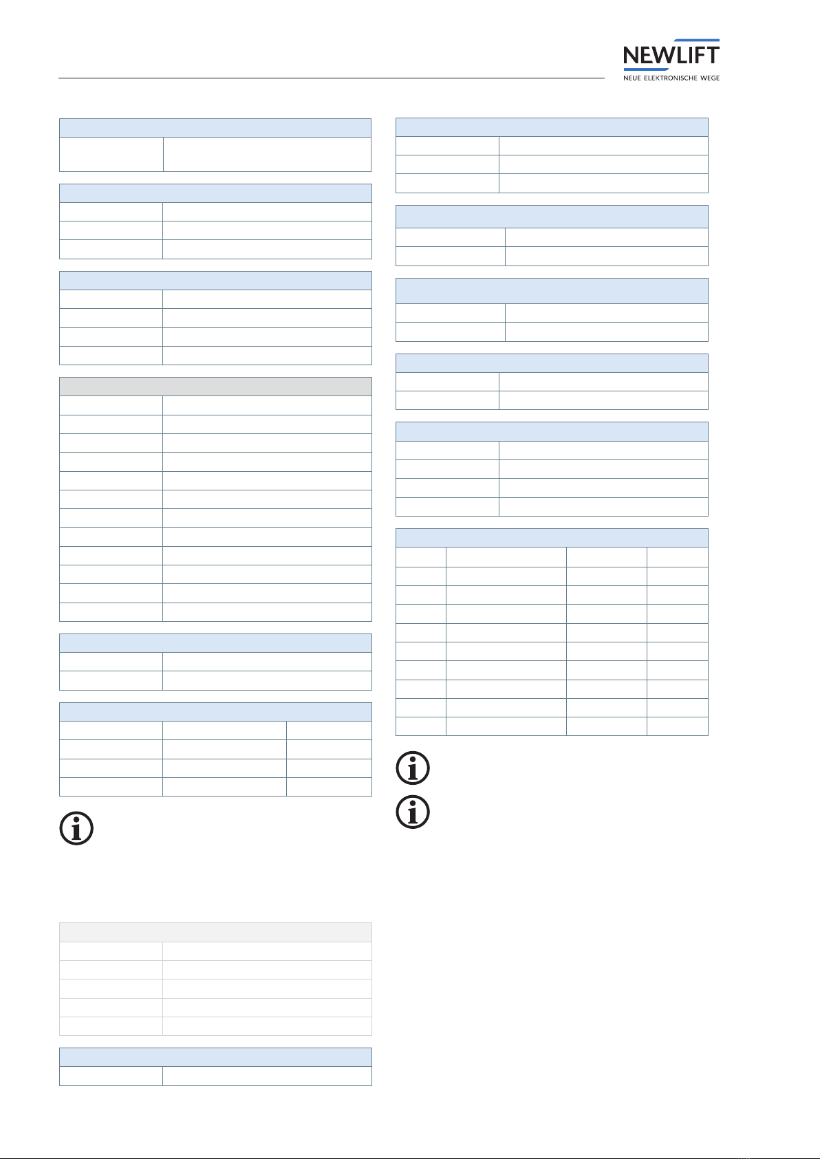
3.3.2 Terminal assignment – EAZ TFT.110 and TFT.210
ESCAPE
ENTERDOWN/LEFTUP/RIGHT
X2
X3
X4
X16
X41
X18
X15
X17
X9/32
JCF
J5
P1
F1
X19
J3
LD5
JS
LD2
LD1
BUZZ1
X25
X21
X24
X22 X23
X26
X28 X29
X27
Schematic diagram – EAZ TFT.110 and TFT.210, rear view
EAZ-TFT.110 and EAZ TFT.210, rear view (HW version 2.2x and higher)

Technical data
Pin assignment
Manual TFT Position indicators 11
EAZ-TFT.210, rear view
Technical data
Pin assignment
12 Manual TFT Position indicators
Fuse
F1 500 mA
(LD1 illuminates if tripped)
LED
LD1 Fuse (red)
LD2 Service (yellow)
LD5 Power (green)
X2 / X3: LON / 24 volt supply
Pin 1 LON data In
Pin 2 LON data Out
Pin 3 +24V
Pin 4 GND
X4: I/O pins
Pin 1 +24V
Pin 2 I/O
Pin 3 I/O
Pin 4 I/O
Pin 5 I/O
Pin 6 I/O
Pin 7 I/O
Pin 8 I
Pin 9 I
Pin 10 GND
Pin 11 I/O
Pin 12 I/O
X15: Gong / loudspeaker connection
Pin 1 Loudsp. + (8 ohm)
Pin 2 Loudsp. + (8 ohm)
X16: Emergency functions (inputs)
Pin 1 "Please wait" + 12-24 V
Pin 2 "Please wait" -
Pin 3 "Please speak" + 12-24 V
Pin 4 "Please speak" -
Change regarding jumpers!
The following applies up to and including HW
version 2.2: Jumpers are present.
The following applies for higher HW versions:
Jumpers are no longer present.
X17: Mini USB port (NEW LIFT internal)
Pin 1 +5 V
Pin 2 Data -
Pin 3 Data +
Pin 4 ID
Pin 5 GND
X18: Loudspeaker 1/2
Pin 1 Channel 1 loud sp. + (8 ohm)
X18: Loudspeaker 1/2
Pin 2 Channel 1 loud sp. – (8 ohm)
Pin 3 Opt.: channel 2 loudsp. + (8 ohm)
Pin 4 Opt: channel 2 loudsp. – (8 ohm)
J5: Boot mode (NEW LIFT internal)
Open Normal operation
Plugged Programming operation
JCF: Function test (NEW LIFT internal)
Open Normal operation
Plugged Programming operation
X19: Emergency power supply (HSG)
Pin 1 +24V
Pin 2 GND
X41: USB 2.0 connection
Pin 1 +5 V
Pin 2 Data -
Pin 3 Data +
Pin 4 GND
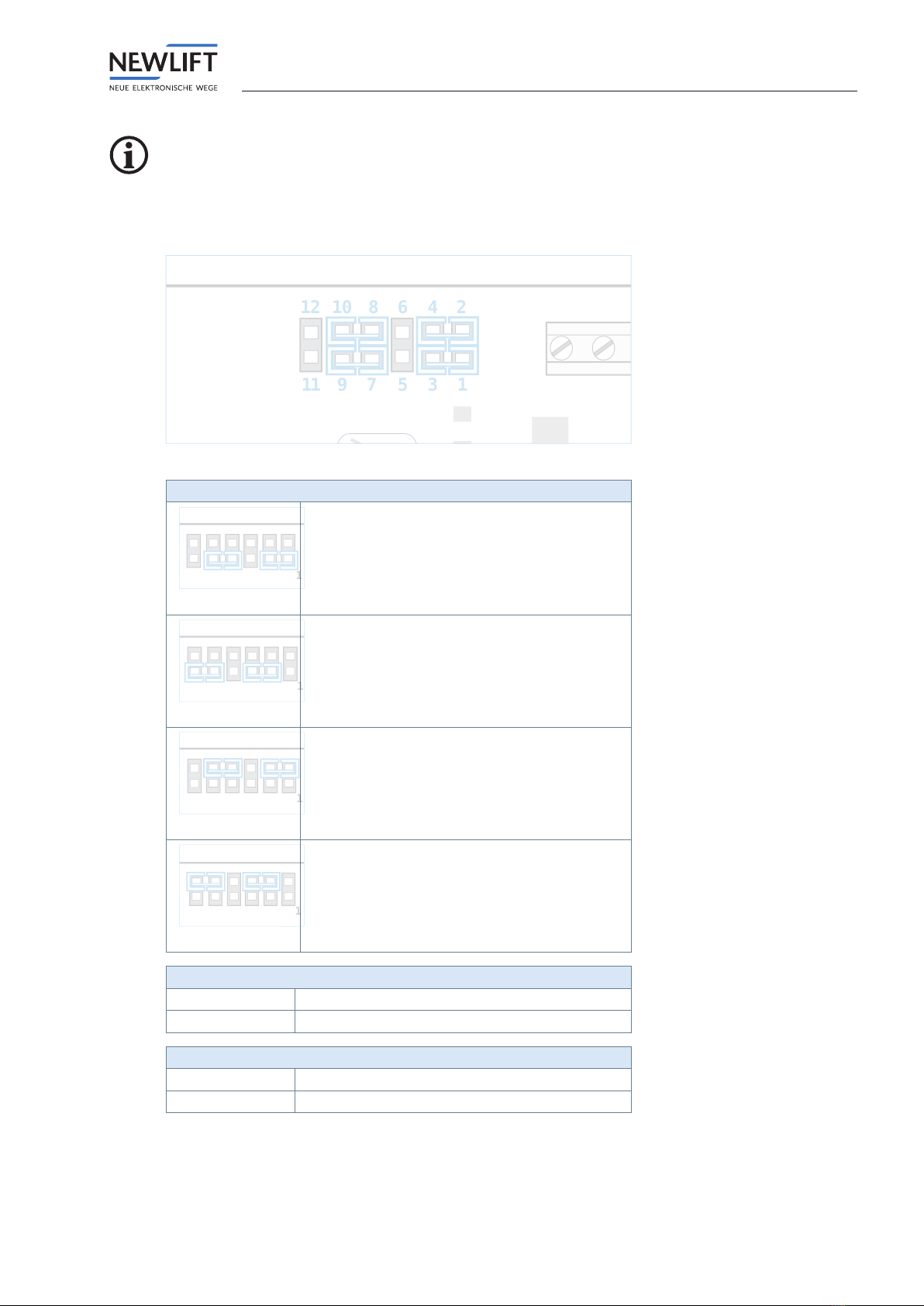
I/O pins (MicroMatch)
Pin 1 Pin 2/3 Pin 4
X21 Enable (X4.11) I/O (X4.12) +24V
X22 Enable (X4.11) I/O (X4.2) +24V
X23 Enable (X4.11) I/O (X4.3) +24V
X24 Enable (X4.11) I/O (X4.4) +24V
X25 Enable (X4.11) I/O (X4.5) +24V
X26 Enable (X4.11) I/O (X4.6) +24V
X27 Enable (X4.11) I/O (X4.7) +24V
X28 GND I/O (X4.8) +24V
X29 GND I/O (X4.9) +24V
Pin 2 and pin 3 are bridged in-circuit.
The assignment is suitable for the following
button modules:
Series MT42 and MA42 buttons from Schaefer.
Technical data
Pin assignment
Manual TFT Position indicators 13
Change regarding jumpers!
The following applies up to and including HW version 2.2: Jumpers are present.
The following applies for higher HW versions: Jumpers are no longer present.
1
2
3
4
5
6
7
8
9
10
11
12
J3: Mode for "Please wait" / "Please speak"
1
1-3 / 7-9
"Please wait" (low active)
1
3-5 / 9-11
"Please wait" (high active)
1
2-4 / 8-10
"Please speak" (low active)
1
4-6 / 10-12
"Please speak" (high active)
J5: Boot mode (NEW LIFT internal)
Open Normal operation
Plugged Programming operation
JCF: Function test (NEW LIFT internal)
Open Normal operation
Plugged Function test

Technical data
Pin assignment
14 Manual TFT Position indicators
3.3.3 I/O pin settings
The I/O pins can be set a) via the LON Module Center or b) via the FST.
For further information, please contact the NEW LIFTservice line!
3.3.4 Emergency functions
Please wait / Please speak
At the inputs Please Waitand Please speak, the respective signals can be fed from the emergency call
unit to the TFT. As soon as the inputs are switched, the corresponding event is triggered.
The Please speaksignal takes precedence over the Please waitsignal.
›The following applies for the onboard design:
The display is permanently programmed. There is a larger status bar containing the Please waitor
Please speakicon.
›The following applies for the custom design:
The events can be congured individually.
Emergency lighting
›The emergency lighting function is an auxiliary luminous panel which is activated in the event of a fault.
›The emergency lighting can be actuated via the bus.
›The emergency lighting is detected if:
»the bus voltage drops (the HSG supply is essential in the case of this condition) or
»if the FSM reports a car lighting fault.
Installation and commissioning
Unpacking
Manual TFT Position indicators 15
4 Installation and commissioning
The EAZ-TFT may only be installed by a trained electrician.
Information on the qualications required by the installing engineer can be found in the manual FST
Installation & Commissioning
See „1.3 Further information“ page 6.
Electrostatic charging
›Keep the electronic assembly in its original packaging until installation to prevent damage.
›Before opening the original packaging, a static discharge must be performed!
To do this, touch a grounded piece of metal.
›During work on electronic assemblies, periodically repeat this discharge procedure!
›Equip all bus inputs/outputs not in use with a terminal resistor (terminator) to prevent malfunctions.
4.1 Unpacking
►Remove the packaging material completely.
►Peel the protective lm off the display screen.
After installation, it is no longer possible to remove the protective lm.
4.2 Installation
The clarity of the display depends on the viewing angle; the installation position of the display is there-
fore critical in achieving an optimum result.
►Determine the installation position before mounting.
►Make sure that the installation position matches the orientation of the display.
›EAZ-TFT.45 – The display is positioned symmetrically on the assembly.
›EAZ-TFT.110 – The display is not positioned symmetrically on the assembly.
›EAZ-TFT.210 – The display is not positioned symmetrically on the assembly.
Pressure or tension can damage the circuit board.
►Do not overtighten the nuts!
Installation and commissioning
Installation
16 Manual TFT Position indicators
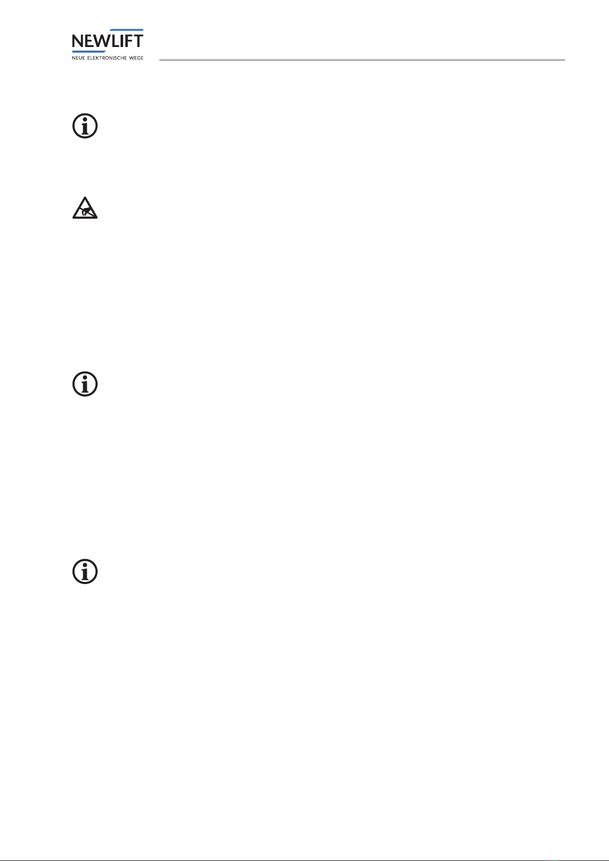
4.2.1 Installation position
Normal installation position
›Normal - Horizontal installation: The LON bus connections are located on the left.
›Normal - Vertical installation: The LON bus connections are located at the bottom.
Normal – Horizontal installation Normal – Vertical installation
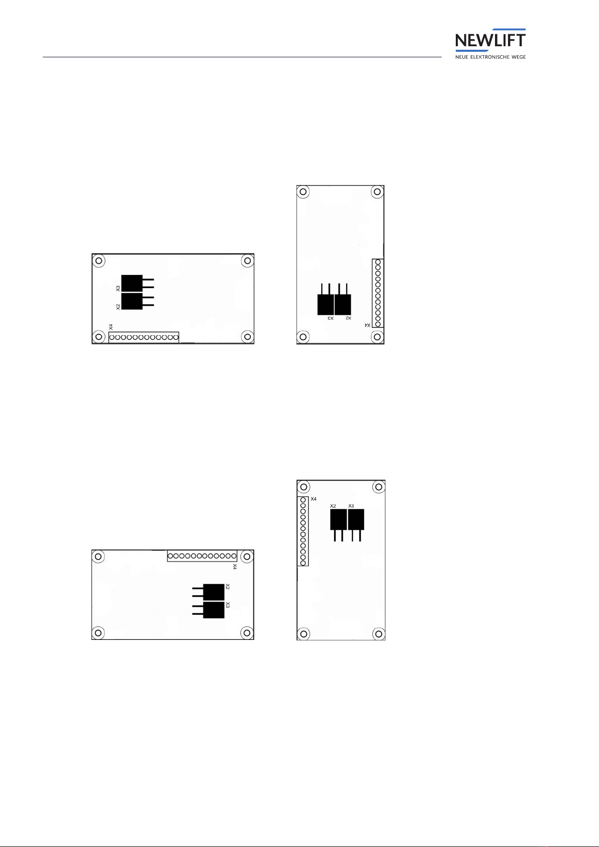
Installation position rotated by 180°
›Rotated by 180° – Horizontal installation: The LON bus connections are on the right.
›Rotated by 180° – Vertical installation: The LON bus connections are at the top.
Rotated by 180° – Horizontal installation Rotated by 180° – Vertical installation
Installation and commissioning
Installation
Manual TFT Position indicators 17
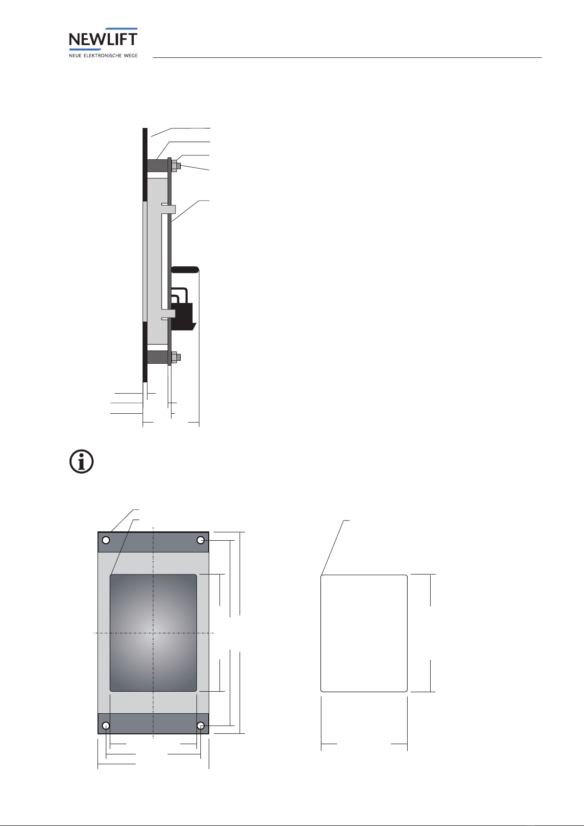
4.2.2 Installation dimensions – EAZ TFT.45
Side view (installed condition)
12,0 mm
Panel
Spacer sleeves
Nut
Threaded pin
M3x16 mm in Panel
2,0 mm
13,6 mm
27,0 mm
EAZTFT45
Tolerance +/- 0,1 mm
The display screen is included in the delivery contents.
Front view display screen Recommended TFT display section
43,0 ±0,24 mm
47,0 mm
55,0 mm
58,0 ±0,28 mm
92,0 mm
100,0 mm
Radius 1mm
Hole 3,6mm
Tolerance +/- 0,1 mm
43,3 mm
58,3 mm
Radius 1,15 mm
Tolerance + 0,1 mm

Installation and commissioning
Installation
18 Manual TFT Position indicators
4.2.3 Installation dimensions – EAZ TFT.110
To allow cable installation, make sure that a gap of 5 mm to adjacent parts is provided on all four sides of the
TFT.110.
Side view (installed condition)
Panel
Spacer sleeve
Nut
Display screen
EAZTFT110
2,0 mm
2,0 mm
8,5 mm
1,6 mm
14,9 mm
Threaded pin M3x16 mm in panel
Installation depth: 30 mm
Tolerance +/- 0,1 mm
The display screen is included in the delivery contents.

Installation and commissioning
Installation
Manual TFT Position indicators 19
Front view with display screen on top
138,0 mm
110,5 mm
67,5 mm
97,2 mm
17 mm
146,0 mm
106,0 mm
Radius
2 mm
4,4 mm
Top
Top
4,0 mm
14,5mm
Tolerance +/- 0,1 mm
Recommended TFT display section
110,6 mm
67,6 mm
Radius
2,05 mm
Tolerance + 0,1 mm

Installation and commissioning
Installation
20 Manual TFT Position indicators
4.2.4 Installation dimensions – EAZ TFT.210
Side view (installed condition)
2,0 mm
12,5 mm
Panel
Spacer sleeve
Display screen
42,5mm
Threaded pin M3 x 16 mm in panel
Nut
EAZTFT210
Tolerance +/- 0,1 mm
The display screen is included in the delivery contents.
This manual suits for next models
2
Table of contents
Other New lift Measuring Instrument manuals


Popular Measuring Instrument manuals by other brands


Fluke Biomedical
Fluke Biomedical RAYSAFE 452 user manual

Kamstrup
Kamstrup MULTICAL 6M2 Installation and user guide

socomec
socomec COUNTIS ECi2 operating instructions

LaserLiner
LaserLiner AutoControl-Master ACM operating instructions

Niigata seiki
Niigata seiki CDI-50 instruction manual

ThermoWorks
ThermoWorks 7000 operating instructions


