NEW TABLE CONCEPT VENGIO User manual

Manual Code UME-TVG03-12/19 www.newtableconcept.com All rights reserved
VENGIO’
USER MANUAL
NTC srl - Sales Office

UME-TVG03-12/19 www.newtableconcept.com
Page 2
SUMMARY
1. INTRODUCTION ___________________________________________________ 3
2. PACKAGE CONTENT _______________________________________________ 3
3. REQUIRED TOOLS _________________________________________________ 3
4. WARNING ________________________________________________________ 4
5. UNPACKING ______________________________________________________ 4
6. PREPARE VENGIO’ FOR WALL MOUNTING ____________________________ 6
7. ASSEMBLY _______________________________________________________ 7
8. OPENING AND CLOSING ___________________________________________ 10
9. CLEANING AND MAINTENAINCE ____________________________________ 10
10. WARRANTY _____________________________________________________ 10

UME-TVG03-12/19 www.newtableconcept.com
Page 3
1. INTRODUCTION
Dear Customer, thank you for choosing the VENGIO’ folding table!
The VENGIO’ folding table is built with high quality materials and extensive attention to detail. The compact
"Counter Weight System" (CWS) is the NTC srl exclusively patented marvel, which ensures everlasting
functionality and beauty.
We are confident that you will appreciate the value of our product and enjoy its convenient, space-saving
and aesthetic features.
2. PACKAGE CONTENT
A - mounting screws (6)
B - adhesive felt pad (2)
C - dowel (6)
D - mounting support (1)
E - Vengiò table (1)
F - holes template (1)
G - mounting plate cover (1)
Fig. 1
WARNING! The screws and dowels we provide are suitable for walls made of solid bricks or concrete. In all
other cases you must use dowels and screws appropriate for the wall in question.
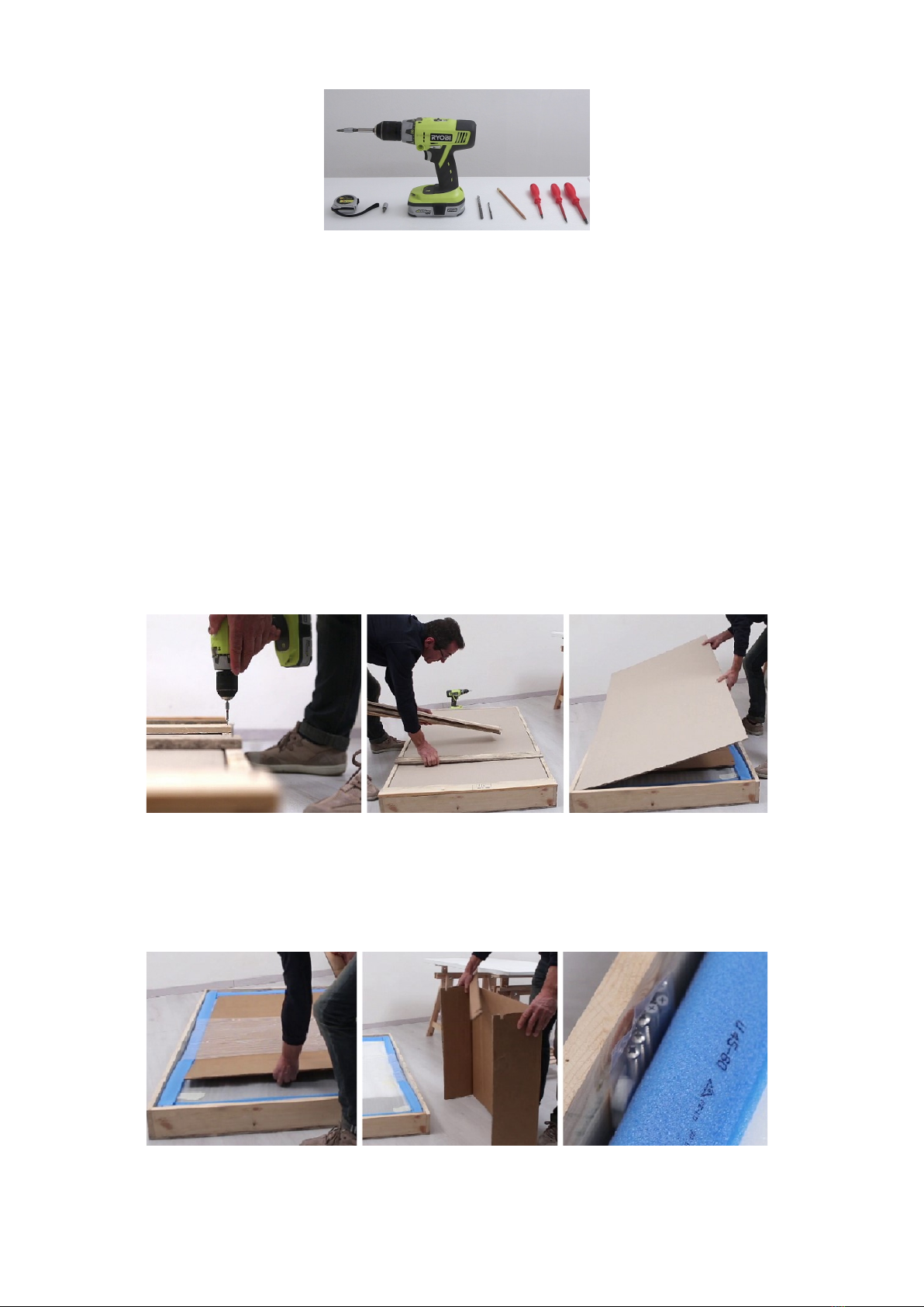
3. REQUIRED TOOLS
The tools you will need are: measuring tape, screwdrivers (electric screwdriver is better), drill, drill bits 6
and 8 mm (1/4” and 5/16”), allen key 4 mm (5/32”) and pencil (Fig. 2).
UME-TVG03-12/19 www.newtableconcept.com
Page 4
Fig. 2
4. WARNING
The table is attached to the wall: all the mechanical stresses are mainly supported by the wall. It is essential
to position the table on a wall suitable to support the table with its load.
The NTC srl ensures the robustness of the table, but is not responsible for any failure due to the wall or to
an insufficient mounting to the wall itself.
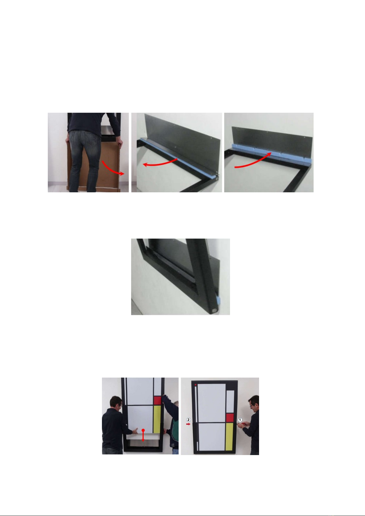
5. UNPACKING
The wooden cage is assembled with nails on one side and with screws on the side which has to be open.
1. Unscrew the cage and remove the wooden bars (Fig. 3 and Fig. 4).
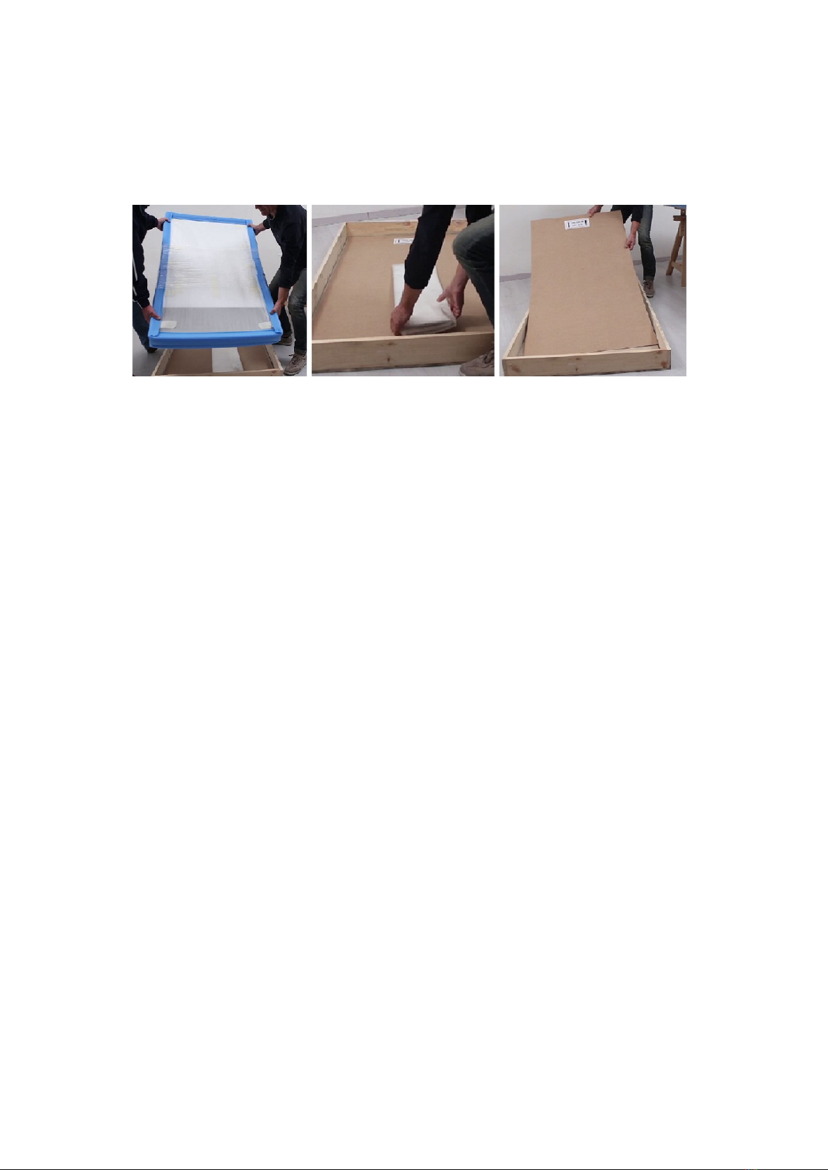
2. Remove the card board protection sheet (Fig. 5).
Fig. 3 Fig. 4 Fig. 5
3. Take out the card board mounting support and assemble it (Fig. 6 and Fig. 7).
4. Take out the screws and dowels bag (Fig. 8).
Fig. 6 Fig. 7 Fig. 8
UME-TVG03-12/19 www.newtableconcept.com
Page 5
5. Take out the Vengiò table and place it on a bench (Fig. 9).
6. Take out the mounting plate cover and store it in a safe place (Fig- 10).
7. Take out the mounting holes template (Fig. 11).
Fig. 9 Fig. 10 Fig. 11
UME-TVG03-12/19 www.newtableconcept.com
Page 6
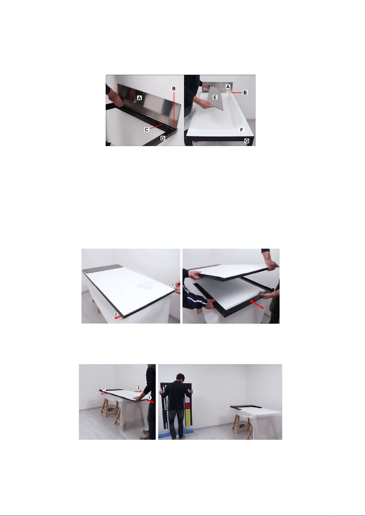
6. PREPARE VENGIO’ FOR WALL MOUNTING
The table is shipped assembled and, to mount it on the wall, it is necessary to partially disassemble it.
Figure 12 shows the table parts that will be referenced later on this manual.
Fig 12
A - mounting plate
B - springs cover
C - springs compartment
D - table frame
E - mounting plate cover
F - table top
G - legs module
1. Place the Vengiò table on a bench and remove the packing material.
2. Unscrew the two M6 cylindrical screws (Fig. 13) and remove the legs module (Fig. 14).
Fig. 13 Fig. 14
3. Unscrew the two M6 conical head screws that fix the table top to the table frame. Remove the table
top (Fig. 15) and place it on the ground using the foam rubber protection (Fig. 16).
Fig. 15 Fig. 16
4. The table frame is now ready for installation.
UME-TVG03-12/19 www.newtableconcept.com
Page 7
7. ASSEMBLY
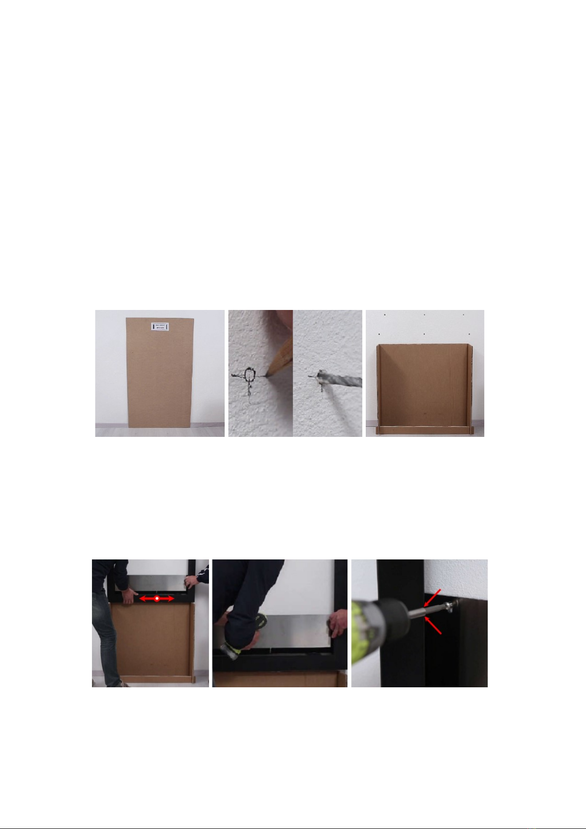
1. Determine the location and make sure the wall can adequately support the table and the stress that
it will be exposed to. The wall should be flat, free from any obstacles (sockets, air intakes, etc.) and
at least 240 cm (95”) high.
2. Place the holes template in the desired position (Fig. 17).
3. IMPORTANT: The position of the holes in the template is not vertically symmetric; there is a label
on the template which identifies the side that must be on top when marking the holes (Fig. 17).
4. Mark with a pencil the six holes.
5. Remove the template and make the holes. To obtain a greater precision, we recommend to make
four lines around the circular mark and to drill the holes first with a small drill bit and then re-drill
with the 8 mm (5/16”) drill bit to enlarge the holes (Fig. 18).
6. Insert the dowels into the holes.
7. Position the mounting support under the holes aligning it with the middle holes (Fig. 19).
Fig. 17 Fig. 18 Fig. 19
8. Position the table frame above the support aligning horizontally the mounting plate holes with the
holes in the wall (Fig. 20).
9. Screw the three upper screws (central one first) of the mounting plate without tightening them (Fig.
21 and Fig. 22). Pay attention to avoid scratching the frame edge when fastening the lateral
screws.
Fig. 20 Fig. 21 Fig. 22
10. Remove the mounting support (Fig. 23).
11. Open the table frame and remove the cm 3x80 blue foam spacer (to be reused a little later) located
UME-TVG03-12/19 www.newtableconcept.com
Page 8
between the springs compartment and the springs cover (Fig. 24).
12. Keeping the frame open, screw the three lower screws of the mounting plate without tightening
them. Pay attention not to scratch the frame.
13. Place the cm 3x80 blue foam spacer between the spring cover and the mounting plate (Fig. 26).
Closing the frame, the cm 3x80 blue foam spacer will keep the frame slightly open to allow the
table top assembly. It will also protect the spring cover against scratches that could be caused by
the mounting plate screws heads.
Fig. 23 Fig. 24 Fig. 25
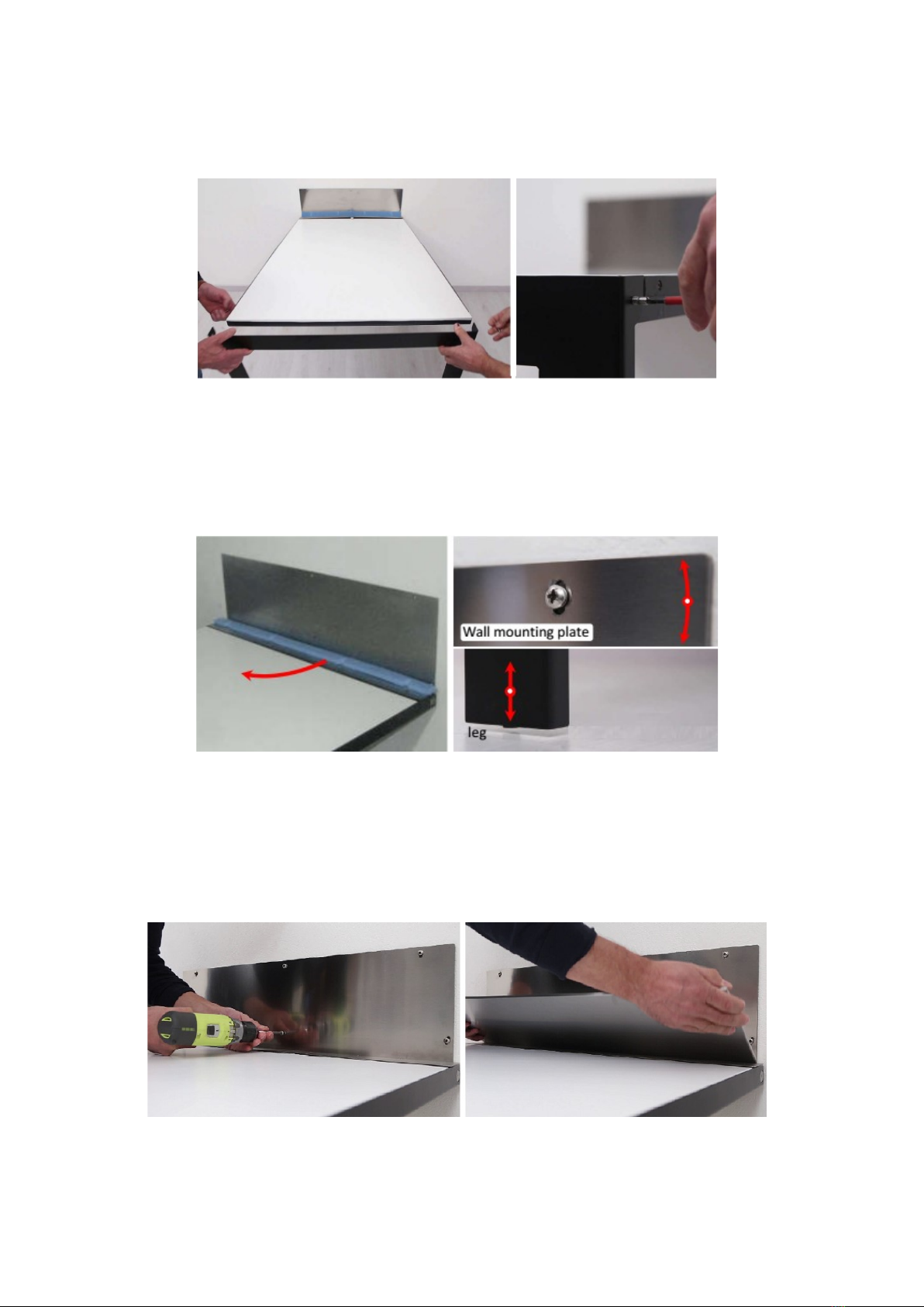
14. Slowly close the table frame. It will remain about 15 degrees open due to the presence of the cm
3x80 cm blue foam (Fig. 26). This will allow the table top assembly.
Fig. 26
15. Slide carefully the table top inside the table frame and make sure the table top will fully slide inside
the table frame (Fig. 27).
16. Screw the table top to the table frame using the two M6 conical head screws (Fig. 28).
Fig. 27 Fig. 28
UME-TVG03-12/19 www.newtableconcept.com
Page 9
17. Open the table and assemble the legs module. Fix the legs module to the table top with the two M6
cylindrical screws (Fig. 29 and Fig 30).
Fig. 29 Fig. 30
18. With the table open, remove the cm 3x80 blue foam spacer (Fig. 31).
19. Make sure both legs touch the floor by rotating the table around the top central screw of the
mounting plate (Fig. 32).
Fig. 31 Fig. 32
20. Tighten the six screws of the mounting plate (Fig. 33). Pay attention not to scratch the frame.
21. Slightly (about half an inch) pull out the springs cover to position the mounting plate cover that will
be fixed magnetically. Put back in position the spring cover on top of the mounting plate cover
(Fig. 34).
Fig. 33 Fig. 34

UME-TVG03-12/19 www.newtableconcept.com
Page 10
22. Close partially the table and position the two adhesive felt pads under the top corners (Fig. 35 and
Fig. 36).
Fig. 35 Fig. 36
8. OPENING AND CLOSING
The opening and closing of the table IS FORBIDDEN to young less than12 years old.
To open the Vengiò folding table, simply pull it away from the wall staying on one side and accompany it to
its open position holding it under the tabletop at about cm 20 from the leg module.
To close the Vengiò folding table, simply lift and accompany it to its closed position staying on one side
using one hand and control with the second hand the leg module making sure the module will not hit the
lifting hand.
The effort required for the opening and closing operations is minimum since the patented "Counter Weight
System" (CWS) reduces dramatically the gravity effect.
The action of the CWS is the same as the gravity action when the table forms about 20 degree with the
wall. In this position, if left, the table will remain in that position in equilibrium.
For angles less than 20 degrees, the CWS action is greater than the gravity action so, if left, the table will
return to its close position (angle 0 degree).
For angles greater than 20 degrees, the gravity action is greater than the CWG action so the table will
rotate toward its open position (angle 90 degree) and has to be accompanied.
IMPORTANT!
WHEN OPENING AND CLOSING, NEWER DROP THE TABLE.
IF THE TABLE IS LEFT AND FALLS FREELY TO THE FLOOR, IT CAN DAMAGE IRRIMEDIABILLY.
9. CLEANING AND MAINTENAINCE
The Vengiò folding table does not require special maintenance. Cleaning can simply be done with a damp
cloth or with a standard furniture cleaning product.
10. WARRANTY
The warranty is valid for two years from shipment date of the product and covers only defective parts or
breakage due to production defects. The warranty does not cover breakage or damage due to improper
use of the table. The broken parts will be replaced free of charge. The shipping expenses will be charged to
the customer.
To make a claim under the warranty, send an e-mail to support@newtableconcept.com with a description
and pictures of the defect.
NTC srl reserves the right to modify the product without any notice.
Table of contents
Popular Indoor Furnishing manuals by other brands


Home Styles
Home Styles 88 9200 002C manual

J D Williams
J D Williams RIGA SG802 Assembly instruction

West Elm
West Elm 5523282 Assembly instructions

West Elm
West Elm Arc Base V2 quick start guide

HunterDouglas
HunterDouglas Duette EasyView Arch Installation, operation & care manual

IBIOM Instruments Ltd
IBIOM Instruments Ltd HEMA+ Operation manual

Happy Beds
Happy Beds homely Malmo Recliner and Stool Assembly instructions

Aqua One
Aqua One Cabinet 53446 Assembly instructions

SouthShore
SouthShore 256 Assembly instructions

C.R. Plastic Products
C.R. Plastic Products Generation Line TB01 Assembly instructions

Polywood
Polywood La Casa Cafe TD102 Assembly instructions

PotteryBarn
PotteryBarn hampton double door cabinet with cubbies manual