NEW VISTA NV1294 User guide

900-D North Macon Street | Baltimore, Maryland 21205
410-342-3820 | FAX 410-342-7324
www.newvistacorp.com
USE AND MAINTENANCE GUIDE
RT HANDHELD THREAD UNIT
Version 1.0 –February 2021

2
CONTENTS
CONTENTS...................................................................................................................... 2
GENERAL DESCRIPTION .................................................................................................. 3
Standard Kit
Customized Unit
METHOD OF OPERATION................................................................................................ 3
MODEL FEATURES .......................................................................................................... 4
Adjustable Torque Clutch
Type FP Tool Chuck and Tool Adapters
Rocker Trigger
Two Speed Gear Drive
Battery Powered
Tool Adapter Overview................................................................................................... 5
Type FP Chuck and Compliant Tool Adapters
FP Tool Adapter for Tapered Shank Tools
FP Tool Adapter for Reversible Tools
FP Tool Adapter for Straight Shank Tools
FP Socket Adapter Tool
Type J Chuck and Tool Adapters
J Tool Adapter for Ring Tools for external threads
J Tool Adapter for BH Gages
J to FP Adapter
Tool Changeover
To Engage a Tool Adapter
To Remove a Tool Adapter
Stop Collars for Depth Verification
GAGE RECOMMENDATIONS............................................................................................ 9
OPERATING INSTRUCTIONS ............................................................................................ 9
Getting Started
TORQUE ADJUSTMENT ................................................................................................... 9
Procedure
3
GENERAL DESCRIPTION
The RT Thread Unit is a cordless Thread Verification Unit for mechanically checking threads or
light thread chasing.
Standard Kit
The RT Thread Unit can be purchased as a standard Kit from New Vista directly or through our
online store: https://www.newvistacorp.com/shop. The Kit comes with everything needed to start
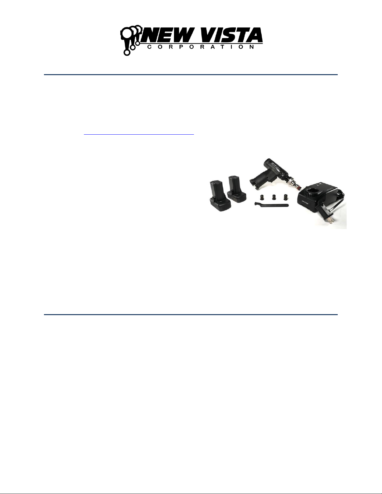
verifying threads using standard taper shank gages. Each Kit includes the following:
•One RT Thread Unit equipped with a
type FP chuck
•Three taper shank gage tool adapters
(for handle sizes no. 0, 1, and 2)
•One torque adjustment tool (a spanner
wrench for 1-1/2” diameter circle with a
7/32” pin)
•Two 14.4V rechargeable lithium-ion
batteries
•One battery charger
Customized Unit
The RT Thread Unit can be customized to meet a wide variety of applications including, but not
limited to, left-hand threads, external threads, restricted-access situations, large threads, and
unique gaging needs. Please contact us to discuss your application.
METHOD OF OPERATION
To operate the unit, place the gage member or cleanout tool at the start of the thread. Align the
axis of the tool with the axis of the hole, push the unit firmly and pull the rocker trigger in the
forward direction. To reverse out of the threaded hole push the rocker trigger in the reverse
direction.
Figure 1
RT Kit Contents
4
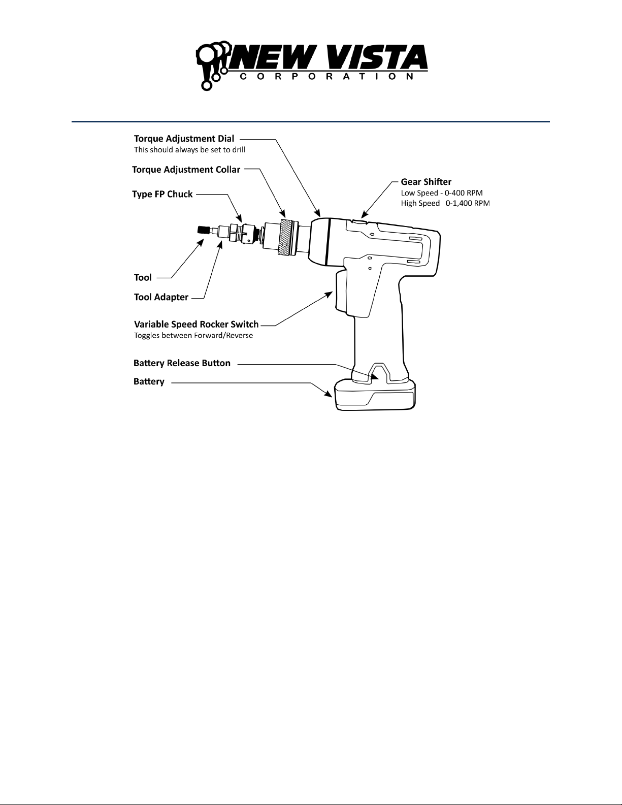
MODEL FEATURES
Figure 2
Adjustable Torque Clutch
The RT Thread Unit comes with a 62020AC New Vista clutch. This sensitive, patented clutch
allows the thread tool to stop harmlessly if there is an obstruction in the thread. The torque in
reverse is always at maximum power to minimize the chance of a tool becoming jammed in a
hole. The forward torque is easily adjustable.
Type FP Tool Chuck and Tool Adapters
The FP chuck, along with the matching FP Tool Adapters, allows for tool changes that take less
than 4 seconds. These compliant tool adapters prevent jamming from misalignment and will
follow the existing thread. FP Tool Adapters are available for three of the most common tool
shank styles: taper, straight, and reversible (fully-threaded).
Custom tool adapters are available to accommodate ring gages or dies for external threads, and
our type BH tool adapters for larger threads sizes or especially deep threads.
Rocker Trigger
The variable-speed rocker trigger gives the user full control over speed and direction, making it
easy to enter a hole and switch to reverse.

5
Two Speed Gear Drive
Two speeds to accommodate your needs:
•Low speed: 0 to 400 RPM
(Typically used for the largest thread sizes or where more torque is required.)
•High speed: 0 to 1,400 RPM
(Default setting for most applications.)
Battery Powered
The RT is powered by a 14.4V Lithium-ion battery that is easily sourced from Snap-on Tools:
https://shop.snapon.com, Item#: CTB8174.
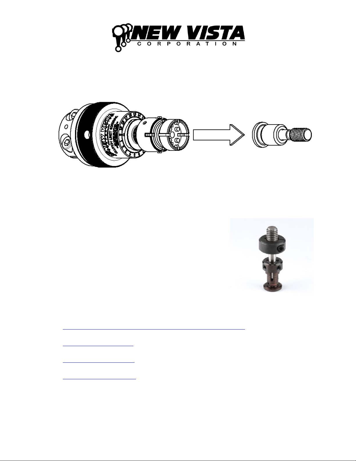
Tool Adapter Overview
Type FP Chuck and Compliant Tool Adapters
This is the standard chuck included in the RT Kit. It allows for
tools to be changed in seconds. All Type FP Tool Adapters provide
compliance. Custom sizes are available for special order. Contact
us with your requirements for application assistance.
FP Tool Adapter for Tapered Shank Tools
We offer five sizes of tool adapters for tapered shank gages/tools.
Taper Size 00
Metric Threads (M3, M3.5)
ANSI Threads (#4, #5, #6)
Taper Size 0
Metric Threads (M4, M5)
ANSI Threads (#8, #10, #12)
Taper Size 1
Metric Threads (M6, M7, M8, M9)
ANSI Threads (1/4”, 5/16”)
Taper Size 2
Metric Threads (M10, M11,M12)
ANSI Threads (3/8”, 7/16”, 1/2”)
Taper Size 3
Metric Threads (M14, M15, M16,
M17, M18, M20)
ANSI Threads (9/16”, 5/8”, 3/4”)
Figure 3
FP Type Chuck
Figure 4
Tapered Shank Gage shown with an
FP Tool Adapter for tapered shank
gages.

6
FP Tool Adapter for
Reversible Tools
FP Tool Adapter for
Straight Shank Tools
FP Socket Adapter Tool
Figure 5
Reversible (Full-Threaded) Gage shown
with an FP Tool Adapter for Reversible
Gages.
Figure 6
Straight-Shank Gage shown with an FP
Tool Adapter for Straight-Shank Gages.
Figure 7
FP Socket Adapter Tool
Reversible (Fully-Threaded)
tool adapters are available in
the following sizes:
Metric Threads: (M5, M6,
M8, M10, M12)
ANSI Threads: (#12, 1/4",
5/16”, 3/8”, 7/16”, 1/2”)
Other sizes are available upon
request.
Tool adapters to accommodate
straight shank tools are
available in 3/16” and 1/4”
sizes. Other sizes are available
upon request.
The FP Socket Adapter Tool
attaches to a standard 3/8”
Socket wrench. It is useful for
extracting a gage that has
become jammed in a thread.
This may happen if the clutch
torque is set at too high a
value for the size of thread.
Type J Chuck and Tool Adapters
This is a custom chuck that accommodates gages for large
threads, external threads, or deep threads. Type J Chucks and
Tool adapters are custom ordered and are not available in the
standard kit. Please contact us for application assistance.
Figure 8
Type J Chuck End

7
J Tool Adapter for Ring Tools
for external threads
J Tool Adapter for BH Gages
J to FP Adapter
Figure 9
These compliant tool adapters can
accommodate ring gages for thread
verification and dies for light chasing of
threads.
Figure 10
Type BH Gages allow for compliance in
larger size gages or in especially deep
threads.
Figure 11
This adapter allows standard type FP
tool adapters to be used on an RT
equipped with a Type J chuck.
Tool Changeover
Both Type FP and Type J tool adapters are designed to be easily changed.
To Engage a Tool Adapter
Align shaft of chuck with the hole in the center of the toolholder then push the tool adapter into
the chuck. Twist the tool adapter in either direction while you are pushing. This helps the drive
pins align with the slots in the toolholder
Figure 12
Twist the tool adapter while inserting it into the chuck.
8
To Remove a Tool Adapter
Pull the tool adapter away from the chuck along the chuck’s axis of rotation.
Figure 13
Pull the tool adapter along the chuck’s axis.
Stop Collars for Depth Verification
Most of the aforementioned tools can be fitted with a stop collar
to verify that the desired depth has been attained. To adjust the
stop collar, simply loosen its screw(s), reposition the collar, and
retighten the screw(s). If the tool has a non-threaded pilot, be
sure to take it into account when setting the depth.
Stop collars are available in many styles. We generally
recommend the split, clamping-style collars. Collars are
available from Misumi with a urethane damper on one side that
helps to prevent marring of the part surface.
Stop collars (shaft collars) are easily obtained from many
sources. Some recommended sources are:
•McMaster-Carr:
https://www.mcmaster.com/stop-collars/clamping-shaft-collars-9
•Misumi:
https://us.misumi-ec.com
•Fastenal:
https://www.fastenal.com
•Grainger:
https://www.grainger.com
Figure 14
GO Gage with Stop Collar

9
GAGE RECOMMENDATIONS
The RT Thread Unit can be used with standard off-the-shelf thread gages and tools.
For typical GO and NO GO thread verification applications we recommend grinding a 45º
chamfer that is equal to 50% of the gage’s major diameter on the end of the gage. This should
remove the cleanout groove on the end of the gage and allow for easier thread engagement.
Figure 15
Gage Chamfering Recommendations
OPERATING INSTRUCTIONS
Getting Started
1. Adjust the torque as necessary.
2. Attach the proper thread tool and tool adapter.
3. Adjust the stop collar to proper depth if you are using one.
4. Use the RT Thread unit as you would a handheld screwdriver.
TORQUE ADJUSTMENT
The torque adjustment collar, located behind the tool adapter, changes the torque setting. This
controls the amount of torque required to make the internal mechanism slip in the
clockwise/forward direction (for right hand threads).
The torque should be adjusted to a level that simulates the torque an operator would output with
a hand gage. You can contact New Vista for recommended torque settings by thread size. In the
counter clockwise/reverse direction (for right hand threads), the unit will apply the full torque
available from the motor to unscrew the tool. This ensures that a tool that has stalled during the
cycle can be unscrewed in reverse.

10
The torque collar is designed to turn stiffly so that a preset torque level it will not change. In
most cases adjustment will require a spanner wrench (included).
Note:
For standard RT Kit Units this setting has not been preset at the factory and
should be set to a torque appropriate for your application.
For custom units this setting is adjusted at the factory and should be tested on-site
before performing any adjustments.
Measuring the torque setting is accomplished by locking two nuts on the thread gage member
and using a torque wrench to measure the stall torque of the clutch. The torque should be
adjusted in small increments and tested to achieve the desired value.
Warning:
We highly recommend that you remove the battery from the unit while
setting the torque.
Do not run the tool in the reverse direction while performing this procedure. The
clutch only slips in one direction. The full torque of the unit will be exerted if the
unit is jogged in the reverse.
Procedure
1. Use a small torque wrench with a range of at least 0-45 in-lbs. (0-5N-m).
2. Remove the battery from the unit.
3. Lock two nuts on the thread gage. Install a matching socket on the torque wrench.
4. With one hand hold the torque wrench with the socket holding the nuts and measure the
torque setting by turning the wrench in the forward (clockwise for right-hand threads)
direction. The actual torque is read while the
clutch is slipping.
5. To adjust the clutch setting, turn the knob to
the required setting. Turning the knob
clockwise increases the amount of torque
needed. If the collar is too hard to turn by hand
use the included spanner wrench.
6. Remove the nuts from the gage.
Torque Adjustment Collar
Use included spanner wrench to
turn.

11
This page intentionally left blank
Table of contents


