Newcastle Systems PC Series User manual

Your Power to Productivity
73 Ward Hill Ave. l Haverhill, MA l 01835 l USA l 781.935.3450 l www.newcastlesys.com
PC Series
ASSEMBLY MANUAL
FOR 1 OR 2 BATTERY SETUP
PC Series 1 & 2 Battery Systems
with 1000W Inverter/Charger
QUESTIONS?CALL 781-935-3450 6-12-2017 Pg. 1
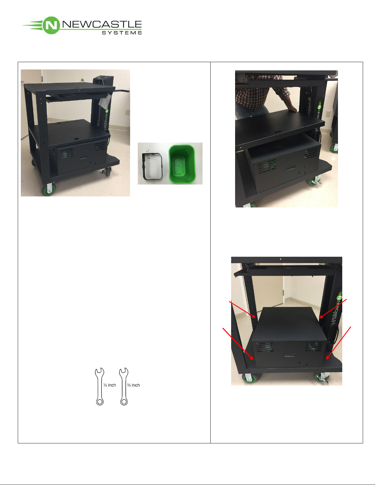
Standard Contents:
- Cart (Assembled)
- Battery & Hardware
- Wastebasket and
Bracket & Hardware
Optional Accessories:
Will either be installed on cart or shipped separately in
box with cart.
**Some accessories may be placed in power cabinet or
trash can for shipping purposes.
Tools Supplied:
(1) 5/32”Allen wrench to remove power box covering
and optional second shelf.
Additional Tools Required:
(2) ½” insulated wrenches (open end or socket) to
tighten battery terminals.
1. If second shelf was purchased, remove it
to gain access to battery box (Allen wrench
required).
Optional second shelf and optional
keyboard tray shown in picture above.
2. Remove (4) screws from the sides of the
battery box (as shown above) with supplied
Allen wrench.

PC Series 1 & 2 Battery Systems
with 1000W Inverter/Charger
QUESTIONS?CALL 781-935-3450 6-12-2017 Pg. 2
3. Remove front
battery panel by
loosening the thumb
screws.
4. Unplug the power
strip from the
inverter/charger.
5. Carefully lift the battery box and make
sure cables stay positioned through the
plastic wire grommet.
Place battery box on its side as shown
below.

PC Series 1 & 2 Battery Systems
with 1000W Inverter/Charger
QUESTIONS?CALL 781-935-3450 6-12-2017 Pg. 3
One Battery Set-Up
(Skip to Page 6 for 2-Battery systems)
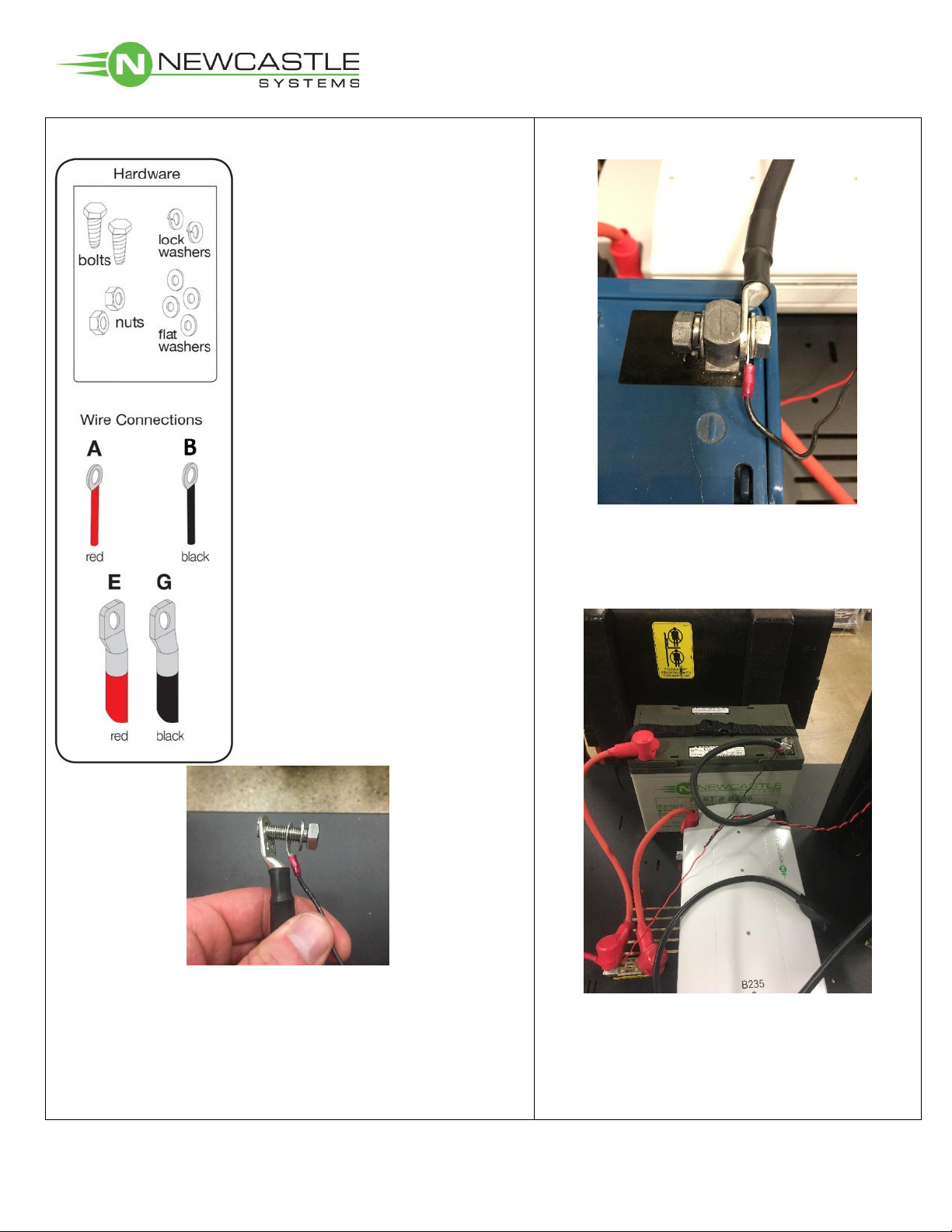
1. Remove battery and hardware from packaging.
2. Carefully place battery on base and
strap down as shown above.
Wire A (red) comes pre-
connected from remote
battery meter to fuse block.
Wire B (black) connects
remote battery meter to
black negative (-) battery
terminal.
(C has been omitted)
Wire E (red) connects to red
positive (+) battery terminal.
(D & F have been omitted)
Wire G (black) connects to
black negative (-) battery
terminal.
Place Battery
here

PC Series 1 & 2 Battery Systems
with 1000W Inverter/Charger
QUESTIONS?CALL 781-935-3450 6-12-2017 Pg. 4
3. Positive Connection: Take bolt and place flat
washer, and large red wire (E) onto bolt (as shown
above); insert bolt through positive (+) battery terminal;
place flat washer, lock washer, then nut onto bolt and
hand-tighten.
Wire A (red) comes pre-
connected from remote
battery meter to fuse block.
Wire B (black) connects
remote battery meter to
black negative (-) battery
terminal.
(C has been omitted)
Wire E (red) connects to red
positive (+) battery terminal.
(D & F have been omitted)
Wire G (black) connects to
black negative (-) battery
terminal.
5. Pull rubber boot over tightened
terminal.
4. Securely tighten terminal bolts with
(2) ½” wrenches.
One Battery Set-up cont.
PC Series 1 & 2 Battery Systems
with 1000W Inverter/Charger
QUESTIONS?CALL 781-935-3450 6-12-2017 Pg. 5
7. Securely tighten terminal bolts with (2)
½” wrenches.
Wire A (red) comes pre-
connected from remote
battery meter to fuse block.
Wire B (black) connects
remote battery meter to
black negative (-) battery
terminal.
(C has been omitted)
Wire E (red) connects to red
positive (+) battery terminal.
(D & F have been omitted)
Wire G (black) connects to
black negative (-) battery
terminal.
6. Negative Connection: Take bolt and place flat
washer, small black wire (B), and large black wire (G)
onto bolt (as shown above); insert bolt through
negative (-) battery terminal; place flat washer, lock
washer, then nut onto bolt and hand-tighten.
One Battery Set-up cont.
Proceed to page 10

PC Series 1 & 2 Battery Systems
with 1000W Inverter/Charger
QUESTIONS?CALL 781-935-3450 6-12-2017 Pg. 6
Two Battery Set-up
(proceed to page 10 if only 1 battery set-up)
1. Remove batteries and hardware from packaging.
Place Battery
#1 here
Place Battery
#2 here
2. Carefully place batteries on base (as
shown above) and securely tighten straps.
Battery #1
Battery #2
Wire A (red) comes pre-connected
from remote battery meter to fuse
block.
Wire B (black) connects remote
battery meter to black negative (-)
terminal of Battery #1.
(C has been omitted)
Wire D1/D2 (black) connects
negative (-) terminal of Battery #1
to negative (-) terminal of Battery
#2. (This wire can be found in clear
plastic bag along w/manual.)
Wire E (red) connects to red
positive (+) terminal of Battery #1.
Wire F (red) connects to red
positive (+) terminal of Battery #2.
Wire G (black) connects to black
negative (-) terminal of Battery #1.
PC Series 1 & 2 Battery Systems
with 1000W Inverter/Charger
QUESTIONS?CALL 781-935-3450 6-12-2017 Pg. 7
Two Battery Set-up cont.
Wire A (red) comes pre-connected
from remote battery meter to fuse
block.
Wire B (black) connects remote
battery meter to black negative (-)
terminal of Battery #1.
(C has been omitted)
Wire D1/D2 (black) connects
negative (-) terminal of Battery #1
to negative (-) terminal of Battery
#2. (This wire can be found in clear
plastic bag along w/manual.)
Wire E (red) connects to red
positive (+) terminal of Battery #1.
Wire F (red) connects to red
positive (+) terminal of Battery #2.
Wire G (black) connects to black
negative (-) terminal of Battery #1.
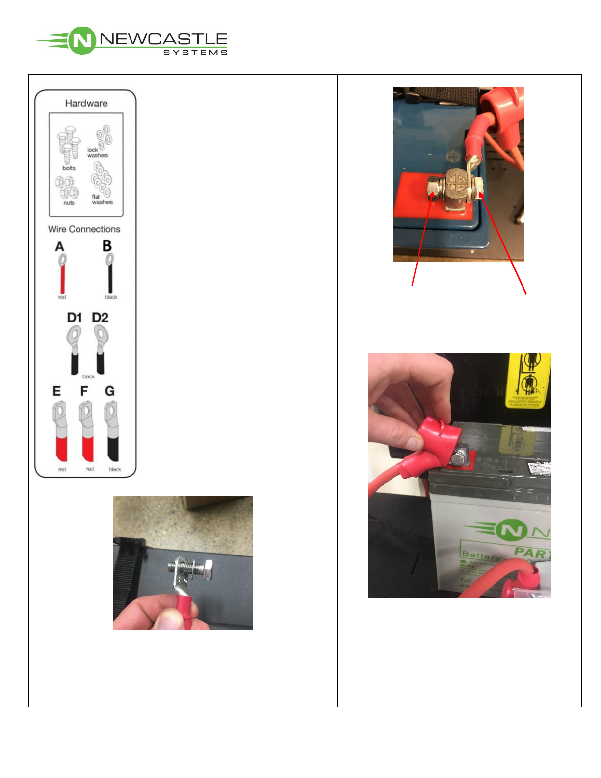
3. Positive Connection, Battery 1: Take bolt and place
flat washer and large red wire (E) onto bolt (as shows
above); insert bolt through positive (+) battery terminal;
place flat washer, lock washer, then nut onto bolt and
hand-tighten.
4. Securely tighten terminal bolts on battery 1
with (2) ½” wrenches.
5. Pull rubber boot over tightened terminal.

PC Series 1 & 2 Battery Systems
with 1000W Inverter/Charger
QUESTIONS?CALL 781-935-3450 6-12-2017 Pg. 8
6. Negative Connection, Battery 1: Take bolt and place
flat washer, small black wire (B), black connector wire
(D1) and large black wire (G) onto bolt (as shown above);
insert bolt through negative (-) battery terminal; place flat
washer, lock washer, then nut onto bolt and hand-tighten.
Wire A (red) comes pre-connected
from remote battery meter to fuse
block.
Wire B (black) connects remote
battery meter to black negative (-)
terminal of Battery #1.
Wire D1/D2 (black) connects
negative (-) terminal of Battery #1
to negative (-) terminal of Battery
#2. (This wire can be found in clear
plastic bag along w/manual.)
Wire E (red) connects to red
positive (+) terminal of Battery #1.
Wire F (red) connects to red
positive (+) terminal of Battery #2.
Wire G (black) connects to black
negative (-) terminal of Battery #1.
(C has been omitted)
Two Battery Set-up cont.
**D1 / D2 battery connector cable can be
found in clear plastic bag w/manual**
7. Securely tighten terminal bolts with (2) ½”
wrenches.
Sparking is normal during initial connection.
PC Series 1 & 2 Battery Systems
with 1000W Inverter/Charger
QUESTIONS?CALL 781-935-3450 6-12-2017 Pg. 9
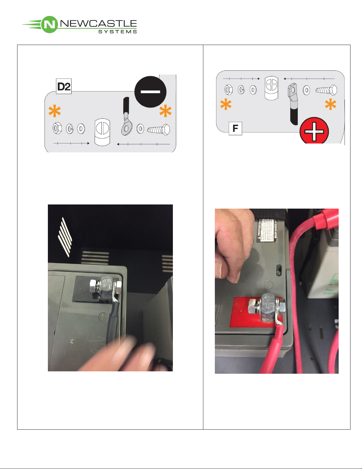
8. Negative Connection, Battery 2: Take bolt and
place flat washer and black connector wire (D2) onto
bolt (as shown above); insert bolt through negative (-)
battery terminal; place flat washer, lock washer, then
nut onto bolt and hand-tighten.
10. Positive Connection, Battery 2: Take
bolt and place flat washer, large red wire
(F) onto bolt (as shown above); insert bolt
through positive (+) battery terminal; place
flat washer, lock washer, then nut onto bolt
and hand-tighten.
9. Securely tighten terminal bolts with (2) ½”
wrenches.
Sparking is normal during initial connection.
11. Securely tighten terminal bolts with (2) ½”
wrenches.
Pull rubber boot over tightened terminal.
Two Battery Set-up cont.

PC Series 1 & 2 Battery Systems
with 1000W Inverter/Charger
QUESTIONS?CALL 781-935-3450 6-12-2017 Pg. 10
3. Run charger cord through cable opening
and securely wrap around cord reel holder.
2-Battery Configuration
Fully Connected
1. Make sure all fittings are tight and that the batteries
are strapped down.
Carefully place the battery box cover on base.
2. Plug the power strip into the
inverter/charger.

PC Series 1 & 2 Battery Systems
with 1000W Inverter/Charger
QUESTIONS?CALL 781-935-3450 6-12-2017 Pg. 11
Testing the Battery Function
1. Turn the unit on by pressing the green power button.
2. Turn the power strip on.
The switch should light red.
3. Reapply the (4) screws to sides of the battery
box with supplied Allen wrench.
4. Place the front battery panel as shown
above.
5. Tighten (4) battery panel thumbscrews.
Accessory assembly manual can be
downloaded at:
www.newcastlesys.com/accessory-assembly

TECHNICAL SUPPORT 781.935.3450 EXT. 3
Tips for Proper Cart Operation
Tips for Proper Cart Operation
• Charge your battery before using it to ensure it is fully charged. Simply plug the charger
cord (located on the side of the unit) into a standard wall outlet.
• Monitor the battery status meter on the cart.
Battery Light Meter Indicators
Voltage 11.2 11.4 11.5 11.7 11.8 12.0 12.1 12.3 12.4 12.6
Light # 1 2 3 4 5 6 7 8 9 10
Color Red
Blinks
Red
Blinks Yellow Yellow Yellow Green Green Green Green Green
• Batteries should not be discharged below 11.5 volts because this will shorten the life of the
battery.
• Batteries
should not
be stored in a discharged state. They should be charged as soon as
possible after each use (otherwise it can void the warranty). If a battery is left in a dis-
charged state for a period of time, it may no longer take a charge.
• Avoid exposing battery to heat, service life is shortened at ambient temperatures above
85F.
• When powering equipment on the cart, it’s okay to have the charger plugged in if neces-
sary. In this case, the AC power will pass through the charger and power your equipment
directly.
• When the cart is not in use, the system charger can be plugged into a wall outlet to ensure
the battery remains in its optimal state. Turn the unit to the OFF position.
Troubleshooting Tips
Is your cart displaying an error code? Here’s what those mean:
ERROR CONDITION MODE SUGGESTED ACTION
E01
Low battery voltage
shutdown, depends on
settings
Inverting
• Check battery status meter and recharge if necessary
• Check that cables are connected properly
• Make sure that cables are secured tightly
E02
High battery voltage
shutdown, greater than
15.5v
Inverting • Check for external charging sources, such as an over
voltage alternator - disconnect if necessary
E03AC output overload shut-
down Inverting
• Reduce the amount of loads connected
• Check the appliances for high-surge ratings and discon-
nect if necessary
E04Over temperature shut-
down Inverting
• Reduce the amount of loads connected
• Check for proper ventilation
• Check for ambient temperature and move to a cooler
location when possible

73 Ward Hill Ave. l Haverhill, MA l 01835 l USA l 781.935.3450 l www.newcastlesys.com
Other manuals for PC Series
1
Table of contents


