manuals.online logo
Brands
  1. Home
  2. •
  3. Brands
  4. •
  5. Ikelite
  6. •
  7. Camera Accessories
  8. •
  9. Ikelite 5510.45 User manual

Ikelite 5510.45 User manual

Thank you for your pur hase of the Ikelite SLR 8" Dome Port. Ikelite
produ ts have been designed and built in the USA for over 40 years
by Ikelite for both the professional and amateur photographer.
This produ t should re eive the same are and attention as your other
photographi produ ts.
IInnssttrruuttiioonn IInnddeexx
Pg 2 ..........................................Important Noti e
Pg 3 ..........................................Important Information
Pg 4 ..........................................Port Bodies
Pg 5 ..........................................Installing Bodies
Pg 6-7 ......................................Installing Port on Housing
Pg 8-11......................................Installing Dome with Super Wide Body
Pg 12 ........................................Optional Repla ement O-rings
Pg 13 ........................................Maintensn e
Pg 14-15....................................Installing Dome Port Shade
Pg 16 ........................................Warranty
Ikelite 8" Dome with Shade
instruction manual
##55551100..4455 IIkkeelliittee DDoommee wwiitthh SShhaaddee
2
I
Im
mp
po
or
rt
ta
an
nt
t
N
No
ot
ti
i
e
e
Port Bodies are engraved with a Maximum Depth Rating,
“RATED 200 FT (60m)”. They are engraved on the flat flange that
rests against the front of the amera housing, see illustration.
Older Standard and Extended Port Bodies that are NOT
ENGRAVED HAVE A MAXIMUM DEPTH RATING OF 150 FEET
(45M). The unmarked Standard or Extended Port Bodies an be
returned to Ikelite for a no harge repla ement with the newer
200 ft. (60m) rated Bodies, DDOO NNOOTTsend the Dome.
5510.16 50mm Port
All Super Wide Bodies are “RATED 200 FT (60m)” Whether
they are engraved or not. DDOO NNOOTTreturn Super Wide Bodies
for ex hange.
Maximum
D pth Rating
ngrav d
on flang
3
CCAAUUTTIIOONN::WWhheenn tthhee ppoorrtt wwiillll nnoott bbee uusseedd ffoorr pprroolloonnggeedd
ppeerriiooddss wwee rreeoommmmeenndd rreemmoovviinngg tthhee BBooddyy ffrroomm tthhee DDoommee
PPoorrtt.. IIff tthhee BBooddyy iiss nnoott rreemmoovveedd ffoorr pprroolloonnggeedd ppeerriiooddss iitt aann
mmaakkee rreemmoovvaall ddiiffffiiuulltt..
For prolonged storage the Port should be removed from the
housing and the Body removed from the Dome Port. The
housing/port o-ring and body/base plate o-rings should be
removed, leaned and lightly lubri ated.
Cover Dome with prote tive over when not in use.
CCAAUUTTIIOONN: Never use spray lubri ants as the propellant
ingredient an ause ra king in this produ t.
PPoorrtt SSeeaall IInnssiiddee VViieeww
Due to the wide overhang of the port
flange the port seal is most visible
when viewed by looking inside the
housing before the amera is inserted.
After the port is installed he k to see
that the o-ring is properly sealed as
shown in FFiigguurree 11and not extruded
as shown in FFiigguurree 22.
Fig. 1
Fig. 2
IImmppoorrttaanntt IInnffoorrmmaattiioonn
4
8” Dome with Shade
PPoorrtt BBooddiieess
For information on the full sele tion of 8” Dome Port Bodies
see the Ikelite atalog or Ikelite web site.
5510.10 33mm Port
5510.16 50mm Port
5510.24 70mm Port
Dome with Shade
#5510.45
Extended Body
#5510.24
Standard Body
#5510.16
Super Wide Body
#5510.10
5510.16 50mm Port
Cam ra Housing / Port Op ning
Dom
Shad
Bas Plat
Cut-outs
6
Strobe
Mount
Rubber
Handle
Quick-Release
Strobe
Mount
Gear Sleeve
Drive Gear
Lid Snap
Lid
Snap
Port Lock
Port Lock
Aluminum Tray
Port o’ring seal area
Port
Opening
I
In
ns
st
ta
al
ll
li
in
ng
g
D
Do
om
me
e
P
Po
or
rt
t
o
on
n
H
Ho
ou
us
si
in
ng
g
See page 8 for installing Super Wide Port on Housing.
PPoorrtt LLookkss
There are two port
lo ks on the front of
the housing. (See
housing front) Ea h
Port Lo k has a Release
Button, lift the release
button and slide ea h
Port Lo k away from
the port opening before
installing the port. In
the unlo ked position
the Release Button will
remain in the up
position as shown.
SlideToOpen
Lift To Unlock
Open Position
Port Lock Release Button
in Locked Position
Port Lock Release Button
in Unlocked Position
Push forward
to Lock —Release Button
will drop down and click into
locked position
Ü
Ü
5
I
In
ns
st
ta
al
ll
li
in
ng
g
B
Bo
od
di
ie
es
s
Install Bodies by
srewing them into
the base plate of the
#5510.45 Dome Port.
The seal between the
Body and the dome
base plate is a piston
seal and requires the
o-ring to be lightly
lubri ated for easy
installation. Remove
the Body/Base Plate
o-ring, put a small
amount of lubri ant
on your fingers and
draw the o-ring
through your fingers to lightly lubri ate it. Do not stret h the
o-ring. Che k that the o-ring groove in the Body where the
o-ring fits and the sealing
surfa e on the port base
plate are lean.
Repla e the o-ring onto the
Body and then s rew the
Body into the base plate of
the dome port. S rew the
Body in until it stops. The
front edge of the Body
should be flush or slightly
above the inside fa e of the
dome base plate as shown
in the ross-se tion.
Dom
Front dg of Body
Fac of Bas Plat
CCrroossss--SSeettiioonn
5510.22 12-24mm / 10-22mm Port
Body
Housing/Port o-ring
Body/Bas Plat o-ring
o-rings
Port Body
7
IInnssttaalllliinngg DDoommee PPoorrtt oonn..
The housing/port
seal is a piston seal
and requires the
Housing/Port
o-ring to be lightly
lubri ated for easy
installation. Put a
small amount of
lubri ant on your
fingers and draw
the o-ring through
your fingers to lightly lubri ate it. Do not stret h the o-ring.
Che k that the lip of the Body where the
o-ring fits and the sealing surfa e on the housing are lean.
Pla e the o-ring ba k onto the Body. Pla e the port, with the
o-ring into the housing’s port opening. Press down on the port
firmly and evenly until you feel the port slide into pla e.
Continue to push down on the port and push ea h port lo k
forward, the Release Button will drop down and li k into the
lo ked position.
Che k around the perimeter of the port seal to see that the
o-ring is properly sealed and not extruded.
SShhaaddee AAlliiggnnmmeenntt
Rotate the port so the 4 ut-outs in the shade are at the 2, 4, 8
and 10 o’ lo k positions in relation to the amera lens.
TToo RReemmoovvee PPoorrtt
To remove the port lift up on ea h Port Lo k Release Button
and slide the port lo k away from the port. Lift port from
housing.
8” Dome with Shade
Housing/
Port o-ring
Cut-outs Cut-outs
8
RReemmoovviinngg SSttaannddaarrdd PPoorrtt LLookk
To remove the Standard Port Lo ks,
uns rew the Port Lo ks retaining
s rew. On e the retaining s rews and
washer are removed the Port Lo ks
an be removed from the housings
mounting blo k.
NNOOTTEE::TThheessee rreettaaiinniinngg ssrreewwss aanndd wwaasshheerr wwiillll NNOOTT bbee rreeuusseedd wwhheenn
iinnssttaalllliinngg tthhee LLooww PPrrooffiillee PPoorrtt LLookkss..
IInnssttaalllliinngg DDoommee wwiitthh SSuuppeerr WWiiddee BBooddyy
The Super Wide port body is supplied with #9072.24 low profile
port lo ks that must be installed on older housings. If the port
lo ks on your SLR-DC housing does not mat h the #9072.24 port
lo ks supplied with the Super Wide body you must remove the
old port lo ks and install the #9072.24 low profile port lo ks.
NNOOTTEE:: TThhee LLooww PPrrooffiillee PPoorrtt LLookkss wwiillll wwoorrkk wwiitthh aannyy IIkkeelliittee ppoorrtt,, oonnee
tthheeyy hhaavvee bbeeeenn iinnssttaalllleedd tthheerree iiss nnoo rreeaassoonn ttoo rreeppllaaee tthheemm..
Standard Port Lock
Port Lock R taining
Scr w
I
In
ns
st
ta
al
ll
li
in
ng
g
t
th
he
e
D
Do
om
me
e
P
Po
or
rt
t
w
wi
it
th
h
S
Su
up
pe
er
rW
Wi
id
de
e
B
Bo
od
dy
y
-
-
o
on
nt
t.
.
S rew the #5510.10
SuperWide Body
into the Base of
the #5510.45 Dome
Port. See page 5,
Installing Bodies.
The #5510.10
SSuuppeerrWWiiddee BBooddyy
iinnssttaallllss oonn tthhee
hhoouussiinngg iinn aa
bbaayyoonneett ffaasshhiioonn.
Before installing
the port onto the
housing push the
Low Profile Port Lo ks
forward into their lo ked
position. Make sure the
Lo k Release Button is
down and lo ked.
The seal between the housing and the port Body is a piston seal
and requires the Housing/Port o-ring be ligtly lubri ated for
easy installation. Remove o-ring from body, put a small amount
of lubri ant on your fingers and draw the o-ring through your
fingers to lightly lubri ate the o-ring. Do not stret h the o-ring.
Che k that the lip of the Body were the o-ring fits and the
sealing surfa e on the housing are lean. Pla e the o-ring ba k
onto the Body.
8” Dome with Shade
5510.10 33mm Port
Dom
Shad
Bas
Plat
Dome with Shade
#5510.45
10
SuperWide Body
#5510.10
Divot
Cut-out
Cut-out
Body/Bas
Plat o-ring
Housing/
Port o-ring
Cut-outs
IInnssttaalllliinngg tthhee DDoommee PPoorrtt wwiitthh SSuuppeerrWWiiddee BBooddyy -- oonntt..
The #5510.10 SuperWide Body has a “ ut-out” on ea h side, see
drawing. Dire tly above one of the “ ut-outs” is a divot in the
fa e of the Body, see drawing page 10. Position the assembled
dome with the “divot” dire tly over one of the Port Lo ks on
the housing. In this position the two “ ut-outs” will be aligned
with ea h of the Port Lo ks for proper installation of the Dome.
Press down on the port firmly and evenly until you feel the port
slide into pla e. Continue to push down and rotate the port
lo kwise until it stops. In this position the port lo k flange is
se ured under ea h of the Low Profile Port Lo ks.
SShhaaddee AAlliiggnnmmeenntt
Che k to see that the 4 ut-outs of the lens shade are at the 2,
4, 8, and 10 o’ lo k positions in relation to the amera lens. If
the shade needs to be adjusted, loosen the 4 set s rews in the
lens shade, position as noted above and then tighten the lens
shade set-s rews. (See pg 15.)
TToo RReemmoovvee PPoorrtt
To remove the port, rotate the port ounter- lo kwise until the
“divot” aligns with the port lo k. Lift port from housing.
SuperWide Body
#5510.10
Dom
Housing/
Port o-ring
Shad
Bas Plat
Cut-out
11
Cut-outs
9
Low Profil Port Lock
I
In
ns
st
ta
al
ll
li
in
ng
g
L
Lo
ow
w
P
Pr
ro
of
fi
il
le
e
P
Po
or
rt
t
L
Lo
o
k
k
Pla e the Low Profile Port Lo k onto the housing, note that the
raised area on the underside of the Low Profile Port Lo k fits
into the large hole on the housing mounting blo k. On e the
Port Lo k is in pla e insert the LLooww PPrrooffiillee RReettaaiinniinngg ssrreeww
((pprroovviiddeedd wwiitthh tthhee LLooww PPrrooffiillee PPoorrtt LLookk))into the s rew hole
as shown, NNoo wwaasshheerr iiss rreeqquuiirreedd. Tighten the s rew down until
the Low Profile Port Lo k will not slide ba k and forth. Now
loosen the Retaining s rew 1/4 turn, just enough to allow the
Low Profile Port Lo k to slide when it is unlo ked.
After the Low Profile Port Lo ks have been installed the port
is ready for installation.
The #5510.82 whi h
utilizes the #5510.10
Body installs in a
bayonet fashion. To
install the port onto
the housing push the
Low Profile Port
Lo ks forward into
their lo ked position.
Make sure the Port
Lo k Release Button
is down and lo ked.
?
Housing
Mounting Block
Low Profil
R taining Scr w
(No wash r)
NNOOTTEE:: TThhee LLooww PPrrooffiillee PPoorrtt LLookkss wwiillll wwoorrkk wwiitthh aannyy IIkkeelliittee ppoorrtt,, oonnee
tthheeyy hhaavvee bbeeeenn iinnssttaalllleedd tthheerree iiss nnoo rreeaassoonn ttoo rreeppllaaee tthheemm..
12
OOppttiioonnaall RReeppllaaeemmeenntt OO--rriinnggss ffoorr AAllll BBooddiieess
O-rings an last for several years if properly maintained, but
it is wise to arry spare o-rings when traveling in ase one
be omes mispla ed or damaged.
5510.22 12-24mm / 10-22mm Port
Body/Bas Plat
o-ring #0132.41
Housing/Port
o-ring #0105
13
CCAAUUTTIIOONN::WWhheenn tthhee ppoorrtt wwiillll nnoott bbee uusseedd ffoorr pprroolloonnggeedd
ppeerriiooddss wwee rreeoommmmeenndd rreemmoovviinngg tthhee BBooddyy ffrroomm tthhee DDoommee
PPoorrtt.. IIff tthhee BBooddyy iiss nnoott rreemmoovveedd ffoorr pprroolloonnggeedd ppeerriiooddss iitt aann
mmaakkee rreemmoovvaall ddiiffffiiuulltt..
For prolonged storage the Port should be removed from the
housing and the Body removed from the Dome Port. The
housing/port o-ring and body/base plate o-rings should be
removed, leaned and lightly lubri ated.
Cover Dome with prote tive over when not in use.
CCAAUUTTIIOONN: Never use spray lubri ants as the propellant
ingredient an ause ra king in this produ t.
M
Ma
ai
in
nt
te
en
na
an
n
e
e
After ea h dive the exterior of the housing and Dome Port
should be rinsed thoroughly in fresh water and dried with a soft
loth. Remove any water spots from the Dome as they an
ause blurry spots in the photographs.
After prolonged saltwater use the exterior of the Dome Port
and housing should be soaked in a mild liquid soap and water
solution. Rinse thoroughly and dry with a soft loth.
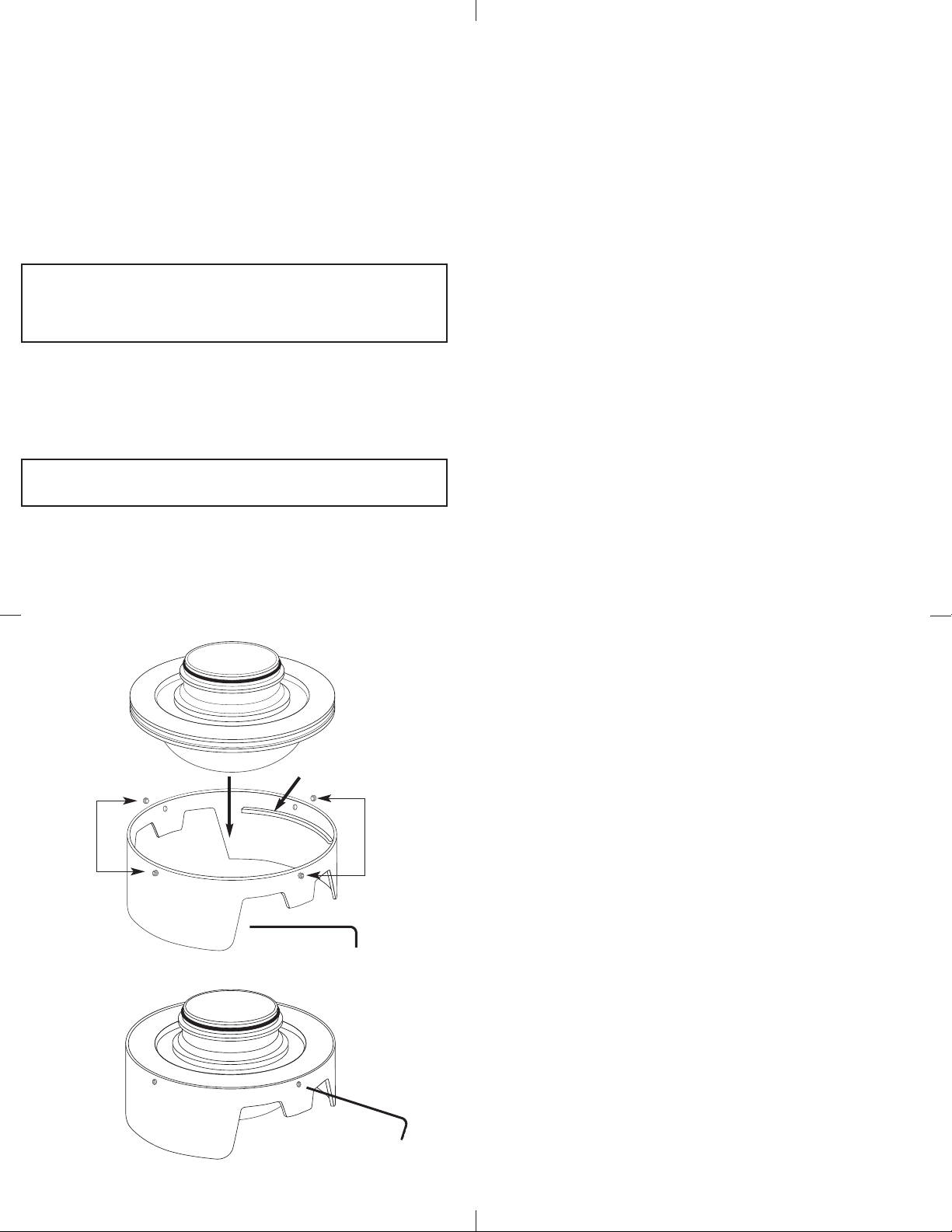
DDoommee PPoorrtt SShhaaddee IInnssttaallllaattiioonn//RReemmoovvaall
1. Pla e the port shade on a flat surfa e with the ut-out
se tion fa e ddoowwnn, as shown in figure 1.
2. Loosen the four set s rews with the Allen wren h. The set
srews do not have to be removed, uns rew them until the
fa e of the set s rew does not protrude beyond the inside
fa e of the dome shade.
3. Carefully pla e the port inside the shade with the
dome fa e ddoowwnn, as seen in figure 2. The dome port should
rest on the two inner ledges of the shade. (see fig.1)
4. Hold the port in pla e and tighten the four set s rews
with the allen wren h provided. Tighten the set-s rews
until the fa e of ea h set-s rew is even with the fa e of
the port shade. (see fig. 2)
CCoovveerr DDoommee wwiitthh NNeeoopprreennee oovveerr ffoorr pprrootteettiioonn
14
S t
Scr ws
Ins rt th
dom port
fac down
S t
Scr ws
Inn r
L dg
All n wr nch
Tight n all four
s t scr ws
with All n wr nch
Plac dom port
shad on a flat
surfac with
cut-outs fac down
DDOOMMEE PPOORRTTFigure 1
DDOOMMEE PPOORRTT SSHHAADDEE
Figure 2
IINNSSTTAALLLLEEDD________________________________________________________________________________________
15
IIkkeelliittee LLiimmiitteedd WWaarrrraannttyy
All Ikelite produ ts are warranted against any manufa turing
defe ts for a period of one year from the date of pur hase.
Defe tive produ ts should be returned prepaid to Ikelite. Ikelite
will, at its dis retion, repair or repla e su h produ ts, and will
return to ustomer prepaid. All other laims, of any nature,
in luding but not limited to bulb failure are not overed. Ex ept
as mentioned above, no other warranty expressed or implied,
applies to this Ikelite produ t.
RReettuurrnniinngg PPrroodduuttss ffoorr SSeerrvviiee
Ikelite is most interested in performing any servi e to assure that
all produ ts perform as intended. For repair or servi e, return the
produ t to the address below with your name, address, phone
number and a brief des ription of the problem. Eviden e of
pur hase date must be provided to obtain warranty servi e.
IIkkeelliittee UUnnddeerrwwaatteerr SSyysstteemmss
5500 WW 3333rrdd SSttrreeeett
IInnddiiaannaappoolliiss,, IINN 4466220088 UUSSAA
331177--992233--44552233
eemmaaiill:: iikkeelliittee@@iikkeelliittee..oomm
wwwwww..iikkeelliittee..oomm
DDoommee wwiitthh SShhaaddee 55551100..4455--0033--00770077

Other manuals for 5510.45

2

Other Ikelite Camera Accessories manuals

Ikelite 6146.19 User manual

Ikelite

Ikelite 6146.19 User manual

Ikelite 200DLM User manual

Ikelite

Ikelite 200DLM User manual

Ikelite WD-3 User manual

Ikelite

Ikelite WD-3 User manual

Ikelite Digital Housing Owner's manual

Ikelite

Ikelite Digital Housing Owner's manual

Ikelite SLR-DC Housing User manual

Ikelite

Ikelite SLR-DC Housing User manual

Ikelite Olympus SP-500 Operating and maintenance manual

Ikelite

Ikelite Olympus SP-500 Operating and maintenance manual

Ikelite 6210.61 Owner's manual

Ikelite

Ikelite 6210.61 Owner's manual

Ikelite S520 Owner's manual

Ikelite

Ikelite S520 Owner's manual

Ikelite 6170.50 User manual

Ikelite

Ikelite 6170.50 User manual

Ikelite 6843.72 User manual

Ikelite

Ikelite 6843.72 User manual

Ikelite DS51 User manual

Ikelite

Ikelite DS51 User manual

Ikelite SLR-DC Housing User manual

Ikelite

Ikelite SLR-DC Housing User manual

Ikelite Nikon L2 User manual

Ikelite

Ikelite Nikon L2 User manual

Ikelite 6950.12 User manual

Ikelite

Ikelite 6950.12 User manual

Ikelite D90 User manual

Ikelite

Ikelite D90 User manual

Ikelite CoolPix S500 User manual

Ikelite

Ikelite CoolPix S500 User manual

Ikelite 6184.7 User manual

Ikelite

Ikelite 6184.7 User manual

Ikelite SD-750 User manual

Ikelite

Ikelite SD-750 User manual

Ikelite 6171.11 User manual

Ikelite

Ikelite 6171.11 User manual

Ikelite 6171.07 User manual

Ikelite

Ikelite 6171.07 User manual

Ikelite SLR-DC Housing User manual

Ikelite

Ikelite SLR-DC Housing User manual

Ikelite 6060 Owner's manual

Ikelite

Ikelite 6060 Owner's manual

Ikelite DCR-SR190 Owner's manual

Ikelite

Ikelite DCR-SR190 Owner's manual

Ikelite 6014.10 Owner's manual

Ikelite

Ikelite 6014.10 Owner's manual

Popular Camera Accessories manuals by other brands

Seitz Roundshot VR Drive s instruction manual

Seitz

Seitz Roundshot VR Drive s instruction manual

Recsea CWC-G7X manual

Recsea

Recsea CWC-G7X manual

ZIV MD-N01 user manual

ZIV

ZIV MD-N01 user manual

BYD Battery-Box Pro series user manual

BYD

BYD Battery-Box Pro series user manual

ION Wi-Fi PODZ quick start guide

ION

ION Wi-Fi PODZ quick start guide

Sinar Sinarback S 30 manual

Sinar

Sinar Sinarback S 30 manual

Olympus FD-1 quick start guide

Olympus

Olympus FD-1 quick start guide

Pix UndercoverEye instruction manual

Pix

Pix UndercoverEye instruction manual

Sanyo KR-5/3MH Cadnica Specifications

Sanyo

Sanyo KR-5/3MH Cadnica Specifications

MYERS MP Series Installation, operation & maintenance manual

MYERS

MYERS MP Series Installation, operation & maintenance manual

ARK Battery Legendary Power 100AH 48V Installation Guide & Specifications

ARK Battery

ARK Battery Legendary Power 100AH 48V Installation Guide & Specifications

Vitec Multimedia aktiv6 user guide

Vitec Multimedia

Vitec Multimedia aktiv6 user guide

Sanyo HR-AAC Specifications

Sanyo

Sanyo HR-AAC Specifications

Victron energy Smart BatteryProtect quick guide

Victron energy

Victron energy Smart BatteryProtect quick guide

Osram HBO 100 Installation and alignment manual

Osram

Osram HBO 100 Installation and alignment manual

walimex PBS-400 instruction manual

walimex

walimex PBS-400 instruction manual

enphase B270-1200-LN-I-EU00-RV0 Quick install guide

enphase

enphase B270-1200-LN-I-EU00-RV0 Quick install guide

Acebil P-32GX Operation manual

Acebil

Acebil P-32GX Operation manual

manuals.online logo
manuals.online logoBrands
  • About & Mission
  • Contact us
  • Privacy Policy
  • Terms and Conditions

Copyright 2025 Manuals.Online. All Rights Reserved.