Newhaven Display International NHD-0420D3Z-FL-GBW-V3 User manual

NHD-0420D3Z-FL-GBW-V3
Serial Liquid Crystal Display Module
NHD- Newhaven Display
0420- 4 Lines x 20 Characters
D3Z- Model
F- Transflective
L- Yellow/Green LED Backlight
G- STN Positive / Gray
B- 6:00 Optimal View
W- Wide Temperature
V3- Firmware Version 3.00
RoHS Compliant
Newhaven Display International, Inc.
2661 Galvin Ct.
Elgin IL, 60124
Ph: 847-844-8795 Fax: 847-844-8796
www.newhavendisplay.com
nhtech@newhavendisplay.com nhsales@newhavendisplay.com

[2]
Document Revision History
Revision
Date
Description
Changed by
0
5/14/2012
Initial Release
SB
1
10/1/2012
Character address code updated
AK
2
12/18/2014
Mechanical drawing & Electrical characteristics updated
AK
3
11/23/15
Module Redesign
SB
4
12/29/16
Backlight & PCB Updated
SB
5
10/1/18
Supply Voltage, Supply Current & I2C Speed Updated
SB
6
6/12/19
SPI & Self-Test Information Updated
SB
Functions and Features
•4 lines x 20 characters
•Serial Interface: I2C, SPI or RS-232(TTL)
•+5.0V power supply
•1/16 duty, 1/5 bias
•5x8 pixels with cursor
•ESD protection diodes
•RoHS Compliant

C
B
A
D
E
F
C
B
A
D
E
F
4321 8765
4321 8765
CHECKED BY:
DRAW N DATE:
10/01/18
NS
SHEET 1 OF 1
- THIRD ANGLE PROJECTION
DRAWING/PART NUMBER:
STANDARD TOLERANCES
(UNLESS OTHERWISE SPECIFIED)
LINEAR:
XX.
XX.X
XX.XX
UNLESS OTHERWISE SPECIFIED
NHD-0420D3Z-FL-GBW-V3
REVISION:
1.0
SIZE:
A3
SCALE:
DRAW N BY:
S. Baxi
CHECKED DATE:
THIS DRAWING IS SOLELY THE PROPERTY OF NEWHAVEN DISPLAY INTERNATIONAL, INC.
THE INFORMATION IT CONTAINS IS NOT TO BE DISCLOSED, REPRODUCED OR COPIED IN
WHOLE OR PART WITHOUT WRITTEN APPROVAL FROM NEWHAVEN DISPLAY.
±0.3 mm
±0.3 mm
±0.3 mm
- DIMENSIONS ARE IN MILLIMETERS
SYMBOL REVISION DATE
DO NOT SCALE DRAWING
S. Baxi
10/01/18
APPROVED BY:
APPROVED DATE:
10/01/18
S. Baxi
Notes:
1. Driver: 1/16 Duty, 1/5 Bias
2. Voltage: 5.0V VDD
3. Display Mode: STN Posive / Gray / Transflecve
4. Opmal View: 6:00
5. Backlight: Yellow-Green LED
6. Driver IC: PIC16F690 & ST7066U
7. Interface: RS232 (TTL) / SPI / I2C

[4]
Pin Description
J1:
Pin No.
Symbol
External Connection
Function Description
1
RX
MPU
RS-232 (TTL) Serial input port
2
VSS
Power Supply
Ground
3
VDD
Power Supply
Supply Voltage (+5.0V)
J2:
Pin No.
Symbol
External Connection
Function Description
1
SPISS
MPU
SPI Slave Select (NC in I2C mode)
2
SDO
NC
No Connect
3
SCK/SCL
MPU
Serial Clock
4
SDI/SDA
MPU
Serial Data In (SPI) / Serial Data (I2C)
5
VSS
Power Supply
Ground
6
VDD
Power Supply
Supply Voltage (+5.0V)
Recommended LCD connector: 2.54mm pitch pins on P1 or P2
Backlight connector: controlled by command Mates with: -
Jumper Communication Selection
R1
R2
Protocol
Description
Short
Short
TEST
Self-test
Open
Short
SPI
100KHz max clock
Short
Open
I2C
50KHz max clock
Open
Open
RS-232
5V, TTL signal

[5]
Electrical Characteristics
Item
Symbol
Condition
Min.
Typ.
Max.
Unit
Operating Temperature Range
TOP
Absolute Max
-20
-
+70
⁰C
Storage Temperature Range
TST
Absolute Max
-30
-
+80
⁰C
Supply Voltage
VDD
-
4.5
5.0
5.5
V
Supply Current (LCD + Backlight)
I
DD
V
DD
= 5.0V
TOP = 25°C
20
32
44
mA
Supply for LCD (contrast)
VLCD
4.0
4.3
4.6
V
“H” Level input
VIH
-
0.7 *VDD
-
VDD
V
“L” Level input
VIL
-
VSS
-
0.6
V
Optical Characteristics
Item
Symbol
Condition
Min.
Typ.
Max.
Unit
Optimal
Viewing
Angles
Top
ϕY+
Cr ≥3
-
20
-
⁰
Bottom
ϕY-
-
40
-
⁰
Left
θX-
-
40
-
⁰
Right
θX+
-
40
-
⁰
Contrast Ratio
Cr
-
3
5
-
-
Response Time
Rise
T
R
TOP = 25°C
-
200
300
ms
Fall
TF
-
250
350
ms
Controller Information
Built-in PIC16F690 controller.
Please download specification at http://www.newhavendisplay.com/app_notes/PIC16F690.pdf

[6]
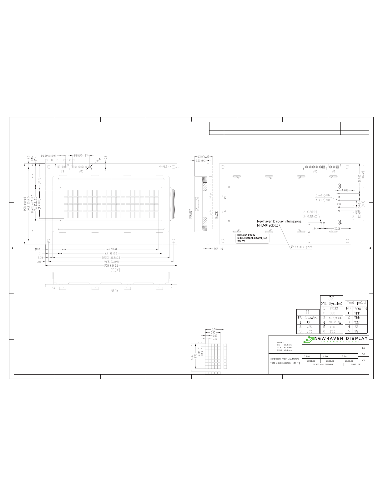
Communication Information
This display uses a built-in PIC16F690 for serial communication.
100mS delay is required upon power-up for the built-in PIC to initialize the display controller.
I2C protocol:
To enter the I2C mode, place a jumper on R1.
SDA and SDK have pull-up resistors (10K Ohm) on R7 and R8.
The default I2C address is 80 (50 hex). The I2C address can be changed to any 8-bit value by command function, with
the exception that the LSB (least significant bit) must always be ‘0’. Once the I2C address has been changed, it will be
saved in the system memory, and it will revert to the default address if either RS-232 or SPI protocol is selected.
The I2C interface can receive data at up to 50KHz clock rate.
SPI protocol:
To enter the SPI mode, place a jumper on R2.
SPI mode has a normally high idle clock. When Slave Select is LOW, data is sampled on the rising edge of the Clock.
The SPI interface can receive data at up to 100KHz clock rate.
SPI Mode 3
CPOL = 1
CPHA = 1
RS-232 (TTL) protocol:
To enter the RS-232 mode, both R1 and R2 should be open.
The RS-232 signal must be 5V TTL compatible. Communication format is 8-bit data, 1 Stop bit, no parity, no handshaking.
Default BAUD rate is 9600 and is changeable with a command function. Once the BAUD rate has been changed, it will be
saved in the system memory, and it will revert to the default address if either I2C or SPI protocol is selected.
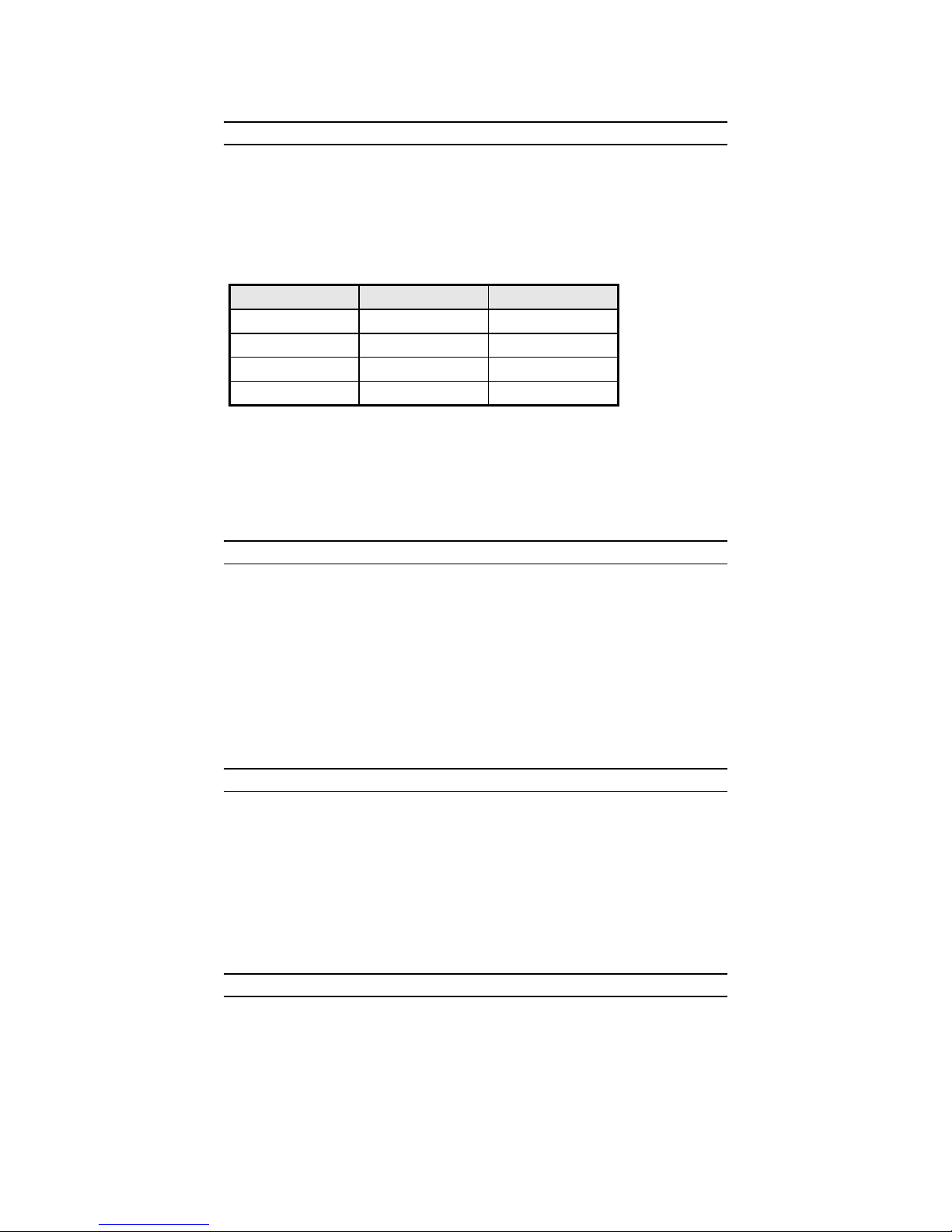
Self-Test Mode
To enter self-test mode, both R1 and R2 should be populated with a 0Ωresistor.
In self-test mode the backlight will be turned on and set to high, the contrast will be set to nominal value. Then the
display returns the following screens:
Screen 1:
-Newhaven Display
Screen 2:
-Firmware Version 3.0
Screen 3:
-Default baud rate: 9600
-Default I2C Slave Address: 0x50
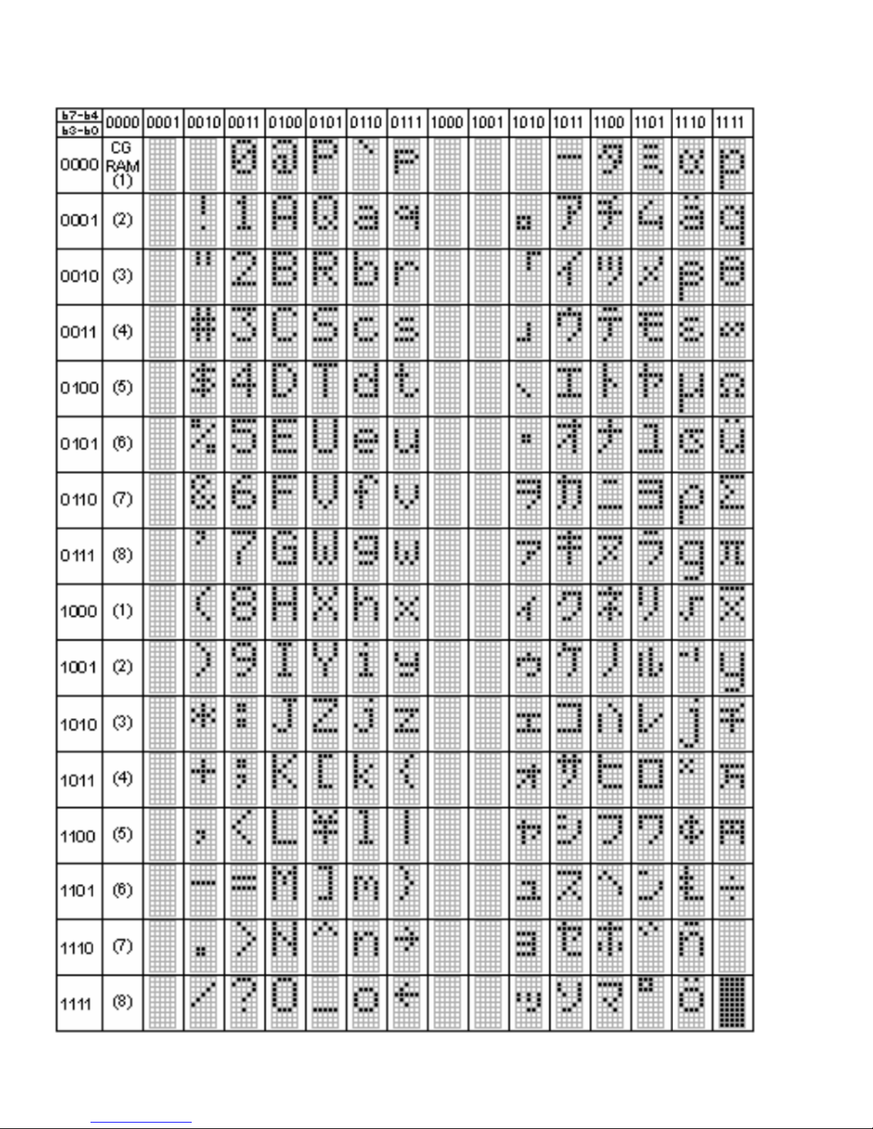
ASCII Text
To display normal text, just enter its ASCII number. A number from 0x00 to 0x07 displays the user defined custom
character, 0x20 to 0x7F displays the standard set of characters, 0xA0 to 0xFD display characters and symbols that are
factory-masked on the ST7066U controller. 0xFE is reserved.

[7]
Table of Commands
Prefix
Command
Parameter
Description
Execution time
-
-
1 Byte
Display Character Write (0x00 ~ 0xFF)
100uS
0xFE
0x41
None
Display on
100uS
0xFE
0x42
None
Display off
100uS
0xFE
0x45
1 Byte
Set cursor
100uS
0xFE
0x46
None
Cursor home
1.5mS
0xFE
0x47
None
Underline cursor on
1.5mS
0xFE
0x48
None
Underline cursor off
1.5mS
0xFE
0x49
None
Move cursor left one place
100uS
0xFE
0x4A
None
Move cursor right one place
100uS
0xFE
0x4B
None
Blinking cursor on
100uS
0xFE
0x4C
None
Blinking cursor off
100uS
0xFE
0x4E
None
Backspace
100uS
0xFE
0x51
None
Clear screen
1.5mS
0xFE
0x52
1 Byte
Set contrast
500uS
0xFE
0x53
1 Byte
Set backlight brightness
100uS
0xFE
0x54
9 Byte
Load custom character
200uS
0xFE
0x55
None
Move display one place to the left
100uS
0xFE
0x56
None
Move display one place to the right
100uS
0xFE
0x61
1 Byte
Change RS-232 BAUD rate
3mS
0xFE
0x62
1 Byte
Change I2C address
3mS
0xFE
0x70
None
Display firmware version number
4mS
0xFE
0x71
None
Display RS-232 BAUD rate
10mS
0xFE
0x72
None
Display I2C address
4mS
Changing the I2C Slave Address
Syntax hexadecimal 0xFE 0x62 [addr]
Parameter Parameter Length Description
[addr] 1 byte New I2C address, 0x00 – 0xFE
The LSB is always ‘0’.
Description This command sets the I2C address. The address must be an even number (LSB = 0). The
address change requires 20 microseconds to take effect; therefore, the subsequent input
must have an appropriate delay. The default I2C address can be restored if SPI or RS-232
is selected as the communication mode.
Default: 0x50

[8]
Changing BAUD Rate
Syntax hexadecimal 0xFE 0x61 [baud]
Parameter Parameter Length Description
[BAUD] 1 byte New RS-232 BAUD Rate, 1 - 8
Description This command sets the RS-232 BAUD rate. The single byte parameter selects the desired
BAUD rate as in the table below. The new BAUD rate requires 20 microseconds to take
effect; therefore, the subsequent input must have an appropriate delay. The default
BAUD rate can be restored if I2C or SPI is selected as the communication mode. Illegal
parameter input will be discarded.
Parameter
BAUD
1
300
2
1200
3
2400
4
9600
5
14400
6
19.2K
7
57.6K
8
115.2K
Default: 9600 BAUD
Turn On Display
Syntax hexadecimal 0xFE 0x41
Parameter Parameter Length Description
None None Turn on LCD screen
Description This command turns on the LCD display screen. The display text is not altered.
Default: LCD screen is on
Turn Off Display
Syntax hexadecimal 0xFE 0x42
Parameter Parameter Length Description
None None Turn off LCD screen
Description This command turns off the LCD display screen. The display text is not altered.
Default: LCD screen is on

[9]
Set Cursor Position
Syntax hexadecimal 0xFE 0x45 [pos]
Parameter Parameter Length Description
[pos] 1 byte Put cursor at location specified by [pos], 0x00 to 0x67
Description This command moves the cursor to a specified location where the next character will be
displayed. The typical cursor position for a 4-line 20-character display is show below; a
cursor position outside these ranges will not be viewable.
Column 1
Column 20
Line 1
0x00
0x13
Line 2
0x40
0x53
Line 3
0x14
0x27
Line 4
0x54
0x67
Default: After a reset, the cursor is on position 0x00
Home Cursor
Syntax hexadecimal 0xFE 0x46
Parameter Parameter Length Description
None None Position cursor at line 1 column 1
Description This command moves the cursor to line 1, column 1 of the LCD screen. The display text is
not altered.
Default: None
Turn On Underline Cursor
Syntax hexadecimal 0xFE 0x47
Parameter Parameter Length Description
None None Turn on underline cursor
Description This command turns on the underline cursor.
Default: Underline cursor is off
Turn Off Underline Cursor
Syntax hexadecimal 0xFE 0x48
Parameter Parameter Length Description
None None Turn off underline cursor
Description This command turns off the underline cursor.
Default: Underline cursor is off

[10]
Move Cursor Left One Space
Syntax hexadecimal 0xFE 0x49
Parameter Parameter Length Description
None None Move cursor left 1 space
Description This command moves the cursor position left 1 space whether the cursor is turned on or
not. The displayed character is not altered.
Default: None
Move Cursor Right One Space
Syntax hexadecimal 0xFE 0x4A
Parameter Parameter Length Description
None None Move cursor right 1 space
Description This command moves the cursor position left 1 space whether the cursor is turned on or
not. The displayed character is not altered.
Default: None
Turn On Blinking Cursor
Syntax hexadecimal 0xFE 0x4B
Parameter Parameter Length Description
None None Turn on the blinking cursor
Description This command turns on the blinking cursor.
Default: The blinking cursor is off
Turn Off Blinking Cursor
Syntax hexadecimal 0xFE 0x4C
Parameter Parameter Length Description
None None Turn off the blinking cursor
Description This command turns off the blinking cursor.
Default: The blinking cursor is off

[11]
Back Space
Syntax hexadecimal 0xFE 0x4E
Parameter Parameter Length Description
None None Move cursor back one space, delete last character.
Description This command is destructive backspace. The cursor is moved back one space and the
character on the cursor is deleted.
Default: None
Clear Screen
Syntax hexadecimal 0xFE 0x51
Parameter Parameter Length Description
None None Clear LCD and move cursor to line 1 column 1.
Description This command clears the entire display and place the cursor at line 1 column 1.
Default: None
Set Display Contrast
Syntax hexadecimal 0xFE 0x52 [contrast]
Parameter Parameter Length Description
[contrast] 1 byte Set the display contrast, value between 1 and 50
Description This command sets the display contrast. The contrast setting can be between 1 and 50,
where 50 is the highest contrast.
Default: 40
Set Backlight Brightness
Syntax hexadecimal 0xFE 0x53 [brightness]
Parameter Parameter Length Description
[brightness] 1 byte Set the backlight brightness level, value between 1 and 8
Description This command sets the backlight brightness level. The value can be between 1 and 8.
Default: 8

[12]
Load Custom Characters
Syntax hexadecimal 0xFE 0x54 [addr] [d0 …d7]
Parameter Parameter Length Description
[addr] 1 byte Custom character address, 0 – 7
[D0...D7] 8 bytes Custom character pattern bit map
Description There is space for eight user-defined custom characters. This command loads the custom
character into one of the eight locations. The custom character pattern is bit mapped
into 8 data bytes. The bit map for Spanish character ‘¿’ is shown in table below. To
display the custom character, user has to enter the address of the character (0 to 8).
Bit
7
6
5
4
3
2
1
0
Hex
Byte 1
0
0
0
0
0
1
0
0
0x04
Byte 2
0
0
0
0
0
0
0
0
0x00
Byte 3
0
0
0
0
0
1
0
0
0x04
Byte 4
0
0
0
0
1
0
0
0
0x08
Byte 5
0
0
0
1
0
0
0
0
0x10
Byte 6
0
0
0
1
0
0
0
1
0x11
Byte 7
0
0
0
0
1
1
1
0
0x0E
Byte 8
0
0
0
0
0
0
0
0
0x00
Default: None
Shift Display to the Left
Syntax hexadecimal 0xFE 0x55
Parameter Parameter Length Description
None None Shift the LCD screen to the left 1 space.
Description This command shifts the display to the left 1 space. The cursor position also moves with
the display, and the display data is not altered.
Default: None
Shift Display to the Right
Syntax hexadecimal 0xFE 0x56
Parameter Parameter Length Description
None None Shift the LCD screen to the right 1 space.
Description This command shifts the display to the right 1 space. The cursor position also moves
with the display, and the display data is not altered.
Default: None

[13]
Display Firmware Version Number
Syntax hexadecimal 0xFE 0x70
Parameter Parameter Length Description
None None Display the firmware version number.
Description This command displays the firmware version.
Default: None
Display RS-232 Baud Rate
Syntax hexadecimal 0xFE 0x71
Parameter Parameter Length Description
None None Display Baud Rate
Description This command displays the RS-232 BAUD rate.
Default: None
Display I2C Address
Syntax hexadecimal 0xFE 0x72
Parameter Parameter Length Description
None None Display I2C Address
Description This command displays the current I2C slave address.
Default: None
Example Initialization Program
See program code at http://www.newhavendisplay.com/app_notes/Serial_LCD.txt

[14]
Built-in Font Table

[15]
Quality Information
Test Item
Content of Test
Test Condition
Note
High Temperature storage
Endurance test applying the high storage
temperature for a long time.
+80⁰C , 48hrs
2
Low Temperature storage
Endurance test applying the low storage
temperature for a long time.
-30⁰C , 48hrs
1,2
High Temperature
Operation
Endurance test applying the electric stress
(voltage & current) and the high thermal
stress for a long time.
+70⁰C 48hrs
2
Low Temperature
Operation
Endurance test applying the electric stress
(voltage & current) and the low thermal
stress for a long time.
-20⁰C , 48hrs
1,2
High Temperature /
Humidity Operation
Endurance test applying the electric stress
(voltage & current) and the high thermal
with high humidity stress for a long time.
+40⁰C , 90% RH , 48hrs
1,2
Thermal Shock resistance
Endurance test applying the electric stress
(voltage & current) during a cycle of low
and high thermal stress.
0⁰C,30min -> +25⁰C,5min ->
+50⁰C,30min = 1 cycle
10 cycles
Vibration test
Endurance test applying vibration to
simulate transportation and use.
10-55Hz , 15mm amplitude.
60 sec in each of 3 directions
X,Y,Z
For 15 minutes
3
Static electricity test
Endurance test applying electric static
discharge.
VS=800V, RS=1.5kΩ, CS=100pF
One time
Note 1: No condensation to be observed.
Note 2: Conducted after 4 hours of storage at 25⁰C, 0%RH.
Note 3: Test performed on product itself, not inside a container.
Precautions for using LCDs/LCMs
See Precautions at www.newhavendisplay.com/specs/precautions.pdf
Warranty Information and Terms & Conditions
http://www.newhavendisplay.com/index.php?main_page=terms
Table of contents
Other Newhaven Display International Control Unit manuals

Newhaven Display International
Newhaven Display International NHD-10.1-HDMI-A-RSXV User manual

Newhaven Display International
Newhaven Display International NHD-12864WG-CTFH-V#N User manual

Newhaven Display International
Newhaven Display International NHD User manual

Newhaven Display International
Newhaven Display International NHD-1.69-AU-SHIELD User manual
Popular Control Unit manuals by other brands

Power Fist
Power Fist 8625279 quick start guide

Plast-O-Matic
Plast-O-Matic RVT Series Installation and maintenance instructions

Atos
Atos LICZO-AEB quick start

Sferalabs
Sferalabs Exo Sense Pi user guide

CleaverBrooks
CleaverBrooks CB780E Installation and operating instructions

Ublox
Ublox TOBY-L1 series System integration manual