Newlec NL5701DALI User manual

IMPORTANT NOTICE
All wirin should be carried out by a competent person or a qualified electrician and should be fitted to IEE 17th Edition Wirin reulations
BS7671:2008. The circuit should be isolated before carryin out any work. Failure to adhere to the instructions will invalidate the warranty.
Instructions
Newlec Helpline: 0800 783 6909 RPM 491
PRODUCT RANGE
NEWLEC DALI OCCUPANCY DETECTOR
PART NUMBER
NL5701DALI
FEATURES
Presence and Absence Detection Options
Automatic Dayliht Harvestin
Settable Timin Modes
Basic Luminaire setup without expensive commissionin
tools
Broadcast and Group Functions
Dual Mode Remote Control
Room & Corridor Options
Manual Lux Level and Sensitivity Control
Coloured Feedback LEDs
Walk Test
Can control LED and fluorescent DALI luminaires
AAbsence Control Lines
AAbsence Control Lines
DA DALI Bus line
DA DALI Bus line
NEWLEC DALI OCCUPANCY DETECTOR WIRING CONNECTIONS
NEWLEC DALI OCCUPANCY DETECTOR INSTRUCTIONS MUST BE READ IN CONJUNCTION WITH REMOTE CONTROL IN
STRUCTIONS IN ORDER TO ENABLE ALL FEATURES OF THE OCCUPANCY DETECTOR
This flush mounted ceilin mount Newlec DALI Occupancy Detector has full DALI flexibility and is the intellient sensor element of
the Newlec DALI network system. It can automatically address the lihtin ballasts without the need for expensive controllers. The
Occupancy Detector is switched on by the detection of movin body heat within a specified rane. When this movin body heat is no
loner detected the unit will dim down the luminaires and eventually switch o. It will also automatically harvest available dayliht to
maximise enery savins. With the remote it is possible to set dimmin time delays and Room and Corridor options. There are also
helpful coloured feedback LEDs to make prorammin easier.
MAINS POWER SHOULD NEVER BE CONNECTED TO ANY TERMINAL OF THE DALI OCCUPANCY DETECTOR
The DALI connections are made to the DA DA bus lines. There is no polarity but it is advisable and ood practice to keep wirin
colours to the same connections for consistency.
Absence detection on the Newlec DALI network system can easily be achieved with the addition of a standard 1 an 1 way switch. If
2 way and intermediate switches are required these can also be connected in to the terminals. To turn this DALI Occupancy Detector
from a presence detector to an absence detector simply connect an ordinary on/o switch to the A and A Absence Control lines and
the Occupancy Detector can be switched between presence and absence mode as desired.
CAREFUL POSITIONING OF THE OCCUPANCY DETECTOR IS ESSENTIAL TO MAINTAIN OPTIMUM DETECTION PERFORMANCE.
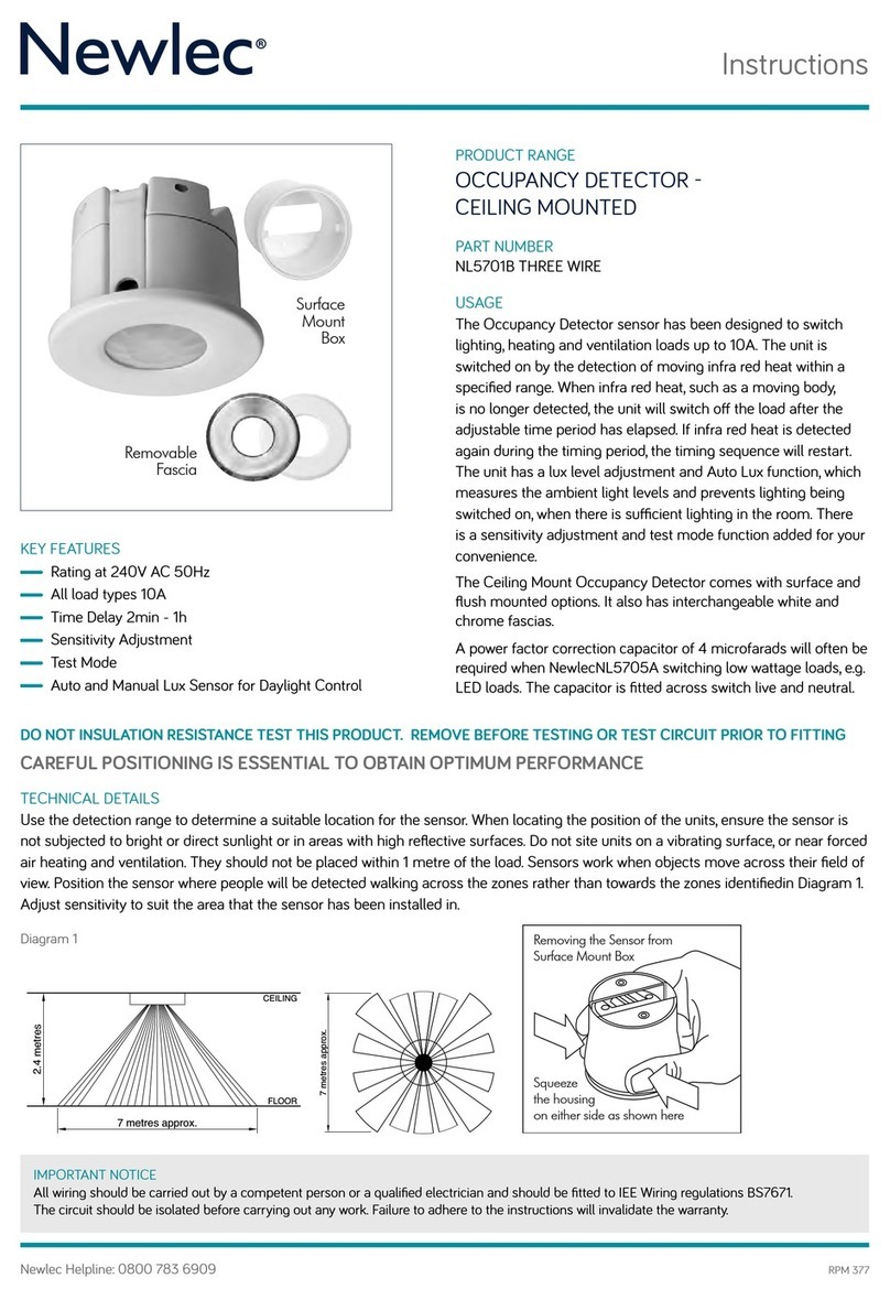
Occupancy Detector detection pattern
2.4 METRES
InstructionData374CMPIRDALI
ElkayeasyDALiPIR
18vd.c.250maforusewithPowerSupplyUnit
(374PSU)
Features
PresenceandAbsenceDetectionOptions
AutomaticDaylightHarvesting
SettableTimingModes
BasicLuminairesetupwithoutexpensivecommissioningtools
BroadcastandGroupFunctions
RemoteControl
Room&CorridorOptions
ManualLuxLevelandSensitivityControl
ColouredFeedbackLEDs
DualModeWalkTest
CancontrolLEDandfluorescentDALIluminaires
ElkayeasyDALiPIRInstructionsmustbereadinconjunction
withRemoteControlInstructionsinordertoenableall
featuresofthePIR.
ThisflushmountedceilingmountElkayeasyDALiPIRhasfullDALI
flexibilityandistheintelligentsensorelementoftheElkayeasyDALI
system.Itcanautomaticallyaddressthelightingballastswithoutthe
needforexpensivecontrollers.ThePIRisswitchedonbythe
detectionofmovinginfraredheatwithinaspecifiedrange.When
thismovinginfraredheatisnolongerdetectedtheunitwilldim
downtheloadandeventuallyswitchoff.Itwillalsoautomatically
harvestavailabledaylighttomaximiseenergysavings.
WiththeremoteitispossibletosetdimmingtimedelaysandRoom
andCorridoroptions.TherearealsohelpfulcolouredfeedbackLEDs
tomakeprogrammingeasier.
ElkayeasyDALIPIRwiringconnections
A
AbsenceControlLines
A
AbsenceControlLines
DA
DALIBusline
DA
DALIBusline
Mainspowershouldneverbeconnectedtoanyterminalof
theeasyDALiPIR.
TheDALIconnectionsaremadeintoDADAbuslines.Thereis
nopolaritybutitisadvisableandgoodpracticetokeep
wiringcolourstothesameconnectionsforconsistency.
ToturnthiseasyDALiPIRfromaPresencedetectortoan
absencedetectorsimplyconnectanordinaryon/offswitchto
theAandAAbsenceControllinesandthePIRwillknow
automaticallythatitisinAbsencemode.
AbsencedetectionontheElkayeasyDALIsystemcaneasily
beachievedwiththeadditionofastandard1gang1way
switch.If2wayandintermediateswitchesarerequiredthese
canalsobeconnectedintotheterminals.
CAREFULPOSITIONINGOFTHEPIRISESSENTIALTO
MAINTAINOPTIMUMDETECTIONPERFORMANCE.
d
AADADA

Instructions
Newlec Helpline: 0800 783 6909
IMPORTANT NOTICE
All wirin should be carried out by a competent person or a qualified electrician and should be fitted to IEE 17th Edition Wirin reulations
BS7671:2008. The circuit should be isolated before carryin out any work. Failure to adhere to the instructions will invalidate the warranty.
RPM 491
BROADCAST MODE
The Newlec DALI Occupancy Detector is set to presence and broadcast mode straiht out of the box and will control even brand new
un-confiured luminaires. In Broadcast Mode the Newlec DALI Occupancy Detector broadcasts DALI control sinals to all luminaires
on the connected DALI network. This is the simplest way to control DALI luminaires. In this way the Newlec DALI Occupancy Detector
is truly a ’wire up and work’ system. For each Power Supply Unit you can have one new broadcast network Occupancy Detector to
control luminaires.
1. Firstly ensure the Newlec DALI Occupancy Detector is set by settin all four dipswitches to o (default factory settin).
2. Simply connect the bus lines in the Occupancy Detector with the Multi-purpose Connection Box and Power Supply Unit in system.
3. The Newlec DALI Occupancy Detector unit will automatically control all the luminaires on that network.
That’s it!
For broadcast mode you have completed set-up at this point and the Occupancy Detector will automatically dayliht harvest and work
as a presence detector or absence detector with the addition of a sinle an one way switch.
SETTING GROUP MODE
There are 15 roups available with the 4 dip switches plus broadcast (see Table 1). As with standard DALI protocol you cannot have
more than one Newlec DALI Occupancy Detector controllin the same lihts on the same roup. The standard DALI protocols ensure
that maximum eciencies are obtained by havin the smallest roups possible. For example, one DALI Occupancy Detector to four
DALI luminaires all set to Group one, another DALI Occupancy Detector controllin six DALI luminaires on Group 2……etc. In order to
proram a roup on the DALI Occupancy Detector the dipswitch must be set first. However in Corridor Option it is possible to have an
Occupancy Detector controllin more than one roup in a corridor or stairwell.
The Newlec DALI Occupancy Detector can control DALI luminaires via a roup address. When a roup is set on the DALI Occupancy
Detector it sends DALI control sinals to DALI luminaires with only that roup address prorammed within the ballast. In this way the
DALI Occupancy Detector can replace an existin Occupancy Detector in a pre-prorammed network provided the roup number is
known. The DALI Occupancy Detector can also proram the ballast within DALI luminaires on a network to work on the currently set
roup (see ‘Add roup to pre-addressed luminaires‘) without the need for expensive commissionin tools. Usin dierent roups, a
number of DALI Occupancy Detectors can control sets of DALI luminaires on the same network, with many manufacturers Occupancy
Detector this is not possible.
TABLE 1 BROADCAST AND GROUP DIPSWITCH SELECTION TABLE
If you require more than one DALI Occupancy Detector on the same DALI network (per DALI Power Supply Unit) you will need to separate Occupancy Detectors with the
roup modes (see ‘Settin Group Mode’).
Please note that the BLACK bar denotes position of the dipswitch

Instructions
IMPORTANT NOTICE
All wirin should be carried out by a competent person or a qualified electrician and should be fitted to IEE 17th Edition Wirin reulations
BS7671:2008. The circuit should be isolated before carryin out any work. Failure to adhere to the instructions will invalidate the warranty.
Newlec Helpline: 0800 783 6909
IMPORTANT NOTICE
All wirin should be carried out by a competent person or a qualified electrician and should be fitted to IEE 17th Edition Wirin reulations
BS7671:2008. The circuit should be isolated before carryin out any work. Failure to adhere to the instructions will invalidate the warranty.
RPM 491
ADD GROUP TO PREADDRESSED DALI LUMINAIRES
Setup of existin luminaires on a DALI network is important even if some or all of the luminaires are not to be controlled by the
Newlec DALI Occupancy Detector currently bein installed. In settin up luminaires the DALI Occupancy Detector updates its list of
DALI addresses currently in use, so that those addressed are not allocated to new luminaires. To et the Occupancy Detector to setup
DALI luminaires:
1. Select the required roup on the DALI Occupancy Detector dip switches as per the Table 1 above.
2. You must turn lihts OFF with the remote first to operate and proram in this mode. To do this, point the remote control at the
DALI Occupancy Detector & press the override o button. While in override o the DALI Occupancy Detector LED flashes white.
3. Set the remote control to installer mode by pressin the hidden installer button inside the battery compartment, the remote control
LED illuminates red.
4. Point the remote control at the Occupancy Detector & press button ‘1‘. The detector will now search the network for luminaires that
have a DALI short address pre-prorammed.
5. Once the search is complete the lamps will pulsate. If you want the Occupancy Detector to control the pulsatin luminaire in
the roup, press the remote control brihtness up button for ‘YES‘ or brihtness down button for ‘NO‘. If ‘YES‘ is pressed the
luminaires ballast is updated with the DALI roup currently set on the Occupancy Detectors dip switches and it updates its address
list and controller list. This luminaire is now in the Occupancy Detectors roup. If ‘NO‘ is pressed only the address list is updated
and the Occupancy Detector will not control this luminaire in that roup selected. Please note twin fluorescent DALI luminaires will
only pulsate if both tubes are enaed in the fittin correctly and are both workin normally.
SET UP FOR BRAND NEW UNADDRESSED DALI LUMINAIRES
The Newlec DALI Occupancy Detector has the ability to do basic setup of brand new luminaires. With the ‘Add new luminaires‘
function, roup and scene information can then be prorammed into the ballast within the luminaire. When new luminaires are
addressed for the first time you must then complete the ‘Add roup to pre-addressed luminaires‘. N.B. If there are existin pre-
prorammed luminaires already on the network skip back to ‘Settin Group Mode‘ first before returnin to this section.
To put the Occupancy Detector into ‘Add new luminaires‘ mode:
PLEASE NOTE THESE INSTRUCTIONS MUST BE READ IN CONJUNCTION WITH THE REMOTE CONTROL INSTRUCTIONS
1. You must turn lihts o first with the remote to operate and proram in this mode. To do this, point the remote control at
the Newlec DALI Occupancy Detector & press the override o button. While in override o the Occupancy Detector LED
flashes white.
2. Set the Dipswitch with the roup number you wish to use for the Occupancy Detector .
3. Set the remote control to installer by pressin the hidden installer button inside the battery compartment, the remote control
LED illuminates red.
4. Point the remote control at the Occupancy Detector & press button ‘2‘ at the bottom of the remote control while the remote
LED is red. The Occupancy Detector will now search for uncommitted DALI ballasts and proram an unused DALI short address.
An uncommitted luminaire will flash up to 5 times. Durin this search the blue sinal LED on the Occupancy Detector will flash
repeatedly.
5. When the Occupancy Detector flashes red the search is completed and any correctly prorammed luminaires on the DALI
network system will be unaected. Once completed the newly setup luminaires can have a roup (see Add roup to‚ pre-
addressed luminaires) and a basic set of scenes (see ‘Set Scenes‘) prorammed into their ballasts.
Any correctly prorammed luminaires on the DALI network will be unaected. Once completed the newly setup luminaire(s)
can have a roup (see Add roup to pre-addressed luminaires.) and a basic set of scenes (see ‘Set scenes’) prorammed into
their ballasts.

Newlec Helpline: 0800 783 6909
IMPORTANT NOTICE
All wirin should be carried out by a competent person or a qualified electrician and should be fitted to IEE 17th Edition Wirin reulations
BS7671:2008. The circuit should be isolated before carryin out any work. Failure to adhere to the instructions will invalidate the warranty.
RPM 491
Instructions
SET SCENES
When a new DALI luminaire is purchased the internal ballast has no scene information prorammed. The Newlec DALI Occupancy
Detector can confiure a basic set of scenes into the ballasts of luminaires that have been setup usin the ‘Add roup to pre-addressed
luminaires’ function. Basic scene setup consists of sixteen scenes, that rane in brihtness from minimum to maximum illumination.
All luminaires on the network with the Occupancy Detector set roup will have their ballast updated with the basic scene set.
Settin scenes on the Occupancy Detector will ive a basic 16 stepped levels of brihtness. When replacin another manufacturers
DALI Occupancy Detector with a Newlec DALI Occupancy Detector it is essential that the roup number is known and set via the dip
switches first. If you want to keep pre-prorammed previous scene information then DO NOT follow ‘Set Scenes‘ below.
1. You must turn lihts o first with the remote to operate and proram in this mode. To do this, point the remote control at
the Newlec DALI Occupancy Detector & press the override o button. While in override o the Occupancy Detector LED
flashes white.
2. Set the Dipswitch with the roup number you wish to use for the Occupancy Detector.
3. Set the remote control to installer by pressin the hidden installer button inside the battery compartment, the remote control LED
illuminates red.
4. Point the remote control at the Occupancy Detector & press button ‘3‘ at the bottom of the remote control while the remote LED
is red. The Occupancy Detector will now flash reen 16 times per ballast and ive a blue flash when scene set is complete.
This process repeats until all ballasts in the roup are set with scenes.
WALK TEST
Walk test can be used to test and setup the Newlec DALI Occupancy Detector sensitivity by movin in & out of the Occupancy
Detector detection rane. The sinal LED on the Occupancy Detector indicates presence by flashin blue and can be used as a basic
walk test. Durin walk test detection the luminaires will be illuminated to full brihtness then after 10 seconds with no presence
detected the luminaires will dim but not o o.
To put the Newlec DALI Occupancy Detector into walk test:
1. You must turn lihts OFF usin the remote first to operate and proram in this mode. To do this, point the remote control at
the Newlec DALI Occupancy Detector & press the override o button. While in override o the Occupancy Detector LED
flashes white.
2. Set the remote control to installer mode by pressin the hidden installer button inside the battery compartment, the remote
control LED illuminates red.
3. Point the remote control at the Occupancy Detector & press the ‘Set‘ button, this will initiate luminaire walk test mode.
4. The LED on the Occupancy Detector will be illuminated blue while presence is detected and the luminaires will be set to full
brihtness. The Occupancy Detector will also flash red and reen to indicate Walk test mode is initiated.
5. Leavin the Occupancy Detector detection zone for more than 10 seconds is indicated by the luminaires bein dimmed & the
LED on the detector bein extinuished.
Walk test mode will be exited after 10 minutes or by pointin the remote at the Newlec DALI Occupancy Detector and pressin any
remote control button. When the walk test is completed point the remote at the Occupancy Detector & press the override o button to
return to normal. The remote control will automatically exit install mode after approximately 2 minutes from the last button press or
can be taken out of installer mode immediately by re-pressin the hidden installer button.
STAIRWELLS
An additional feature of the Corridor Mode option makes it possible to have more than one roup switched by a DALI Occupancy
Detector. This means that luminaires in the current roup or floor can be selected as well as other floors in the stairwell. Simply see
the ‘Add roup to pre-addressed luminaires’ and select YES for every luminaire you wish to be controlled in the stairwell. This flexibility
allows you to maximise enery savins in stairwells.

NEWLEC DALI OCCUPANCY DETECTOR FEEDBACK COLOURS AND FLASH STATUS
The Newlec DALI Occupancy Detector flashes several feedback colours via its LED to let you know what state it is in.
The followin table indicates the states that it is showin after installation.
CALCULATING MAXIMUM RATIOS OF DALI OCCUPANCY DETECTORS TO BALLASTS IN A SINGLE NETWORK
Each Newlec DALI Occupancy Detector is capable of runnin 64 ballasts (althouh in reality that will not be sensible practice).
In order to calculate the maximum numbers of Occupancy Detectors and luminaires that can be on the same network, use the
followin equation.
180 - (Lx2)
14
Where L = number of DALI luminaires
Worked Example 1
20 ballasts
For example 20 ballasts x 2 =40
180-40 = 140
140 = 10
14
Therefore maximum 10 detectors for 20 ballasts
POSITIONING OF THE DETECTOR
CAREFUL POSITIONING IS ESSENTIAL TO OBTAIN OPTIMUM PERFORMANCE
Use the detection rane to determine a suitable location for the sensor. When locatin the position of the units, ensure the sensor is
not subjected to briht or direct sunliht or in areas with hih reflective surfaces. Do not site units on a vibratin surface, or near forced
air heatin and ventilation. They should not be placed within 1 metre of the load. Sensors work when objects move across their field of
view. Position the sensor where people will be detected walkin across the zones rather than towards the zones identified in diaram 1.
Adjust sensitivity to suit the area that the sensor has been installed in.
MODE PIR COLOUR STATE
PRESENCE
Lihts OFF No Flash No flashes at the Occupancy Detector indicates no detection and lihts will be OFF. There are no absence wall switches involved in this circuit.
PRESENCE
Lihts ON
When operatin in normal presence mode sensor LED blinks BLUE when there is presence detection and presence detected.
PRESENCE
OFF by Remote
In presence mode even if lihts are switched o by Remote Control the sensor will flash WHITE (even if presence not detected i.e. no one is in
the room). This is to let you know the system has been switched o by remote control.
ABSENCE
Lihts ON
If there are wall switches in this circuit wired into the A A position and the wall switch is operated, the LEDS on the sensor will blink BLUE then
RED to indicate presence detected and absence mode is set.
ABSENCE
Lihts OFF
Sensor continues to blink RED with lihts o to indicate sensor is in absence mode (even if presence not detected. i.e. no one is in the room).
If lihts are switched o by Remote control and are in absence mode the sensor will also flash RED (even if presence not detected).
CORRIDOR
Option
In corridor option a reenish YELLOW flash will indicate presence detected and in corridor option.
CORRIDOR Option
(Hibernation)
Occupancy Detector is in Corridor Option and two WHITE flashes indicates it has been switched o completely by remote (Hibernation).
When the remote ON/OFF button is re-pressed the Occupancy Detector will resume in corridor mode.
Remote Button
Press
When any button is pressed on the Remote Control a reen flash confirms acceptance at the Occupancy Detector.
(Note GREEN flashes need to be counted when Selectin Room and Corridor Options- see Table X on the Remote Control Instructions).
Newlec Helpline: 0800 783 6909
IMPORTANT NOTICE
All wirin should be carried out by a competent person or a qualified electrician and should be fitted to IEE 17th Edition Wirin reulations
BS7671:2008. The circuit should be isolated before carryin out any work. Failure to adhere to the instructions will invalidate the warranty.
IMPORTANT NOTICE
All wirin should be carried out by a competent person or a qualified electrician and should be fitted to IEE 17th Edition Wirin reulations
BS7671:2008. The circuit should be isolated before carryin out any work. Failure to adhere to the instructions will invalidate the warranty.
RPM 491
Instructions
Worked Example 2
40 ballasts
40 ballasts x 2 =80
180-80 = 100
100 = 7 (rounded up)
14
Therefore maximum 7 detectors for 40 ballasts

Newlec Helpline: 0800 783 6909 Manufacturers Address: Newey & Eyre Eale Court 2, Hatchford Way, Birminham B26 3RZ
IMPORTANT NOTICE
All wirin should be carried out by a competent person or a qualified electrician and should be fitted to IEE 17th Edition Wirin reulations
BS7671:2008. The circuit should be isolated before carryin out any work. Failure to adhere to the instructions will invalidate the warranty.
RPM 491
Instructions
The complete Newlec DALI network solution is provided with just four elements
NEWLEC DALI NETWORK SOLUTION OVERVIEW
The Newlec DALI network solution has been desined to make installation and set-up of a Newlec DALI system quicker and easier
for installers. With the increasin enery savin requirements to cut emissions and enery bills for consumers and businesses alike,
Newlec’s DALI network solution is here to meet these demands.
Newlec have achieved this by makin the first rane of sensors that can automatically confiure DALI lihtin ballasts, as well as the
more commonly used broadcast mode. The system provides presence and absence detection and delivers dayliht harvestin to
ensure maximum enery eciency. The Newlec DALI Occupancy Detector is a presence, absence and dayliht harvestin sensor all
rolled into one.
In a brand new ‘out of the box’ installation of new DALI luminaires and with a new Newlec DALI Occupancy Detector, you can simply
wire the lihtin, the Power Supply Unit and the Occupancy Detector toether with the Multi-Purpose Connection Box and simply
accept the default settins of…
Broadcast mode
Timin
Dayliht Harvestin
…and the Occupancy Detector with just a few pushes of the remote control will find and address all luminaires control ear on the
network and the installation is complete.
With just a few more button selections on the Occupancy Detector and the remote controller, the product can easily set up roups
and scenes as well as corridor modes, additional timin modes and the Occupancy Detector will also automatically dayliht harvest to
maximise enery savins.
Unlike some manufacturers systems Newlec’s DALI Occupancy Detector sensors can be wired to control their own set of luminaires
usin in built DALI roup functions to ive control by roup and not just by broadcast alone.
Newlec DALI Occupancy
Detector
Newlec DALI Dual Purpose
Remote Control
Newlec DALI Power Supply Unit Newlec DALI multi-purpose
connection box
Imae
Part No. NL5701DALI NL5711 NL5712 NL5713
Features •Presence and Absence
VDetection
•Automatic Dayliht
VHarvestin
•Default Timin Modes
•Broadcast and Group
VFunctions
•Room & Corridor Mode
•Manual Lux Level and
VSensitivity Control
•Coloured Feedback LEDs
•Walk Test
•Dual Purpose control
Voptions for End user and
VInstallers
•Sets all non-default
Vfunctions
•Sets Timin Room Modes
Vand Corridor Modes
•Sets Min Arc Levels
•25%, 50% and 100%
Vbrihtness pre sets
•Override Functions
•Remote Lux Control
•Remote Feedback LEDs
•3 x AAA Batteries supplied
•18V d.c. 250mA
•Connects to Multi-Purpose
VConnection Box
•Essential to supply power
Vto DALI network
•10A Max for Lihtin loads
•Connects Lihtin (ALL
VTYPES) and DALI network
•Connects Power Supply
Table of contents
Other Newlec Security Sensor manuals
Popular Security Sensor manuals by other brands
Riken Keiki
Riken Keiki RX-516 Operation manual
Vanderbilt
Vanderbilt IS443 installation manual
Magellan
Magellan MG-PMD1P installation manual
UTC Fire and Security
UTC Fire and Security interlogix DI601AM Installation sheet

PureAire Monitoring Systems
PureAire Monitoring Systems BC TX-FM instruction manual
Evikon
Evikon E2630-HFC user manual
