15272 Newsboy Circle
Huntington Beach
California 92649
Phone: 714-751-0488
Fax: 714-896-9679
www.newmartelecom.com
Section/Figure Topic Page
1.0 Quick Reference Guide.......................................................................................... 1
2.0 Overview................................................................................................................ 2
2.1 GeneralDescription................................................................................................ 2
2.15 Front Panel LED Indicators..................................................................................... 2
2.2 SensorInputs........................................................................................................... 2
2.2.1 Voltage: DC & AC.................................................................................................. 2
2.2.2 Current & Switch Inputs......................................................................................... 2
2.2.3 Ambient Temperature Sensor................................................................................ 3
2.3 System Requirements............................................................................................. 3
2.4 Materials Provided................................................................................................. 3
2.5 Optional Accessories.............................................................................................. 3
3.0 Installation............................................................................................................. 4
3.1 Mechanical............................................................................................................ 4
3.2 Wiring..................................................................................................................... 4
3.2.1 DC Operating Power Input 9-60 vdc..................................................................... 4
3.2.2 DC Voltage Monitoring Ports.................................................................................. 5
3.2.3 DCCurrent.............................................................................................................. 5
3.2.4 Dry Contact Switch Sensors.................................................................................... 5
3.2.5 AC Voltage Monitoring.......................................................................................... 5
3.2.6 EthernetConnection............................................................................................... 5
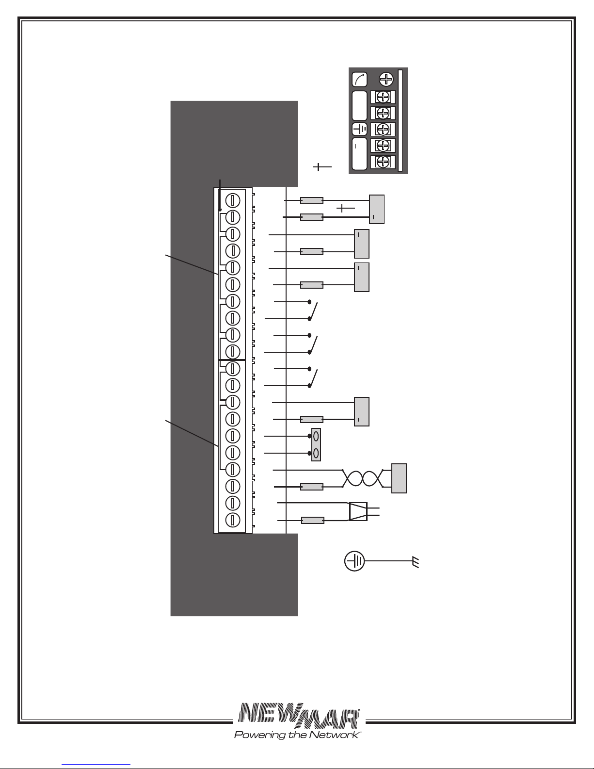
Figure/Table 1 Input Terminal Block Assignments........................................................................ 6
Figure 2 Simplified Install Wiring Guide............................................................................... 7
4.0 Set-up Monitoring & Data Logging........................................................................ 8
4.1 Basic Software Set-up............................................................................................. 8
4.1.1 InitialSet-up............................................................................................................ 8
4.1.2 NICSet-up............................................................................................................... 9
Figure 3 Web Page: NIC Settings for Unit at Default IP....................................................... 9
Figure 4 SPM-200 Homepage (Un-Configured Unit)............................................................ 10
Figure 5 Factory Default User Name & Password................................................................ 10
4.1.3 Setting the Clock……………………………………...................................................... 11
Figure 6 Web Page: Setting the Clock.................................................................................. 11
5.0 SPM-200 Web Page Overview............................................................................... 12
Figure 7 Web Page: SPM 200 Sensors (Unconfigured Unit.................................................. 12
Figure 8 Web Page: SPM 200 Sensors (Configured Unit)….................................................. 13
5.1 Setting Low & High Alarm Trips............................................................................. 14
Figure 9 Web Page: Alarms Page....................................................................................... 14
5.2 Cameras Page....................................................................................................... 14
Figure 10 Web Page: Logging Page...................................................................................... 15
Figure 11 Web Page: Display Page....................................................................................... 15
5.3 Configuration Page................................................................................................ 16
Figure 12 Web Page: Top of Configuration Page.................................................................. 16
5.3.1 Reset All to Default Values..................................................................................... 16
5.3.1.1 AC Voltage Offset................................................................................................... 16
5.3.2 Zero Current Channel............................................................................................ 16