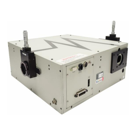
Newport 500B Series User manual

-~
ARTISAN
®
~I
TECHNOLOGY
GROUP
Your definitive source
for
quality
pre-owned
equipment.
Artisan Technology
Group
Full-service,
independent
repair
center
with
experienced
engineers
and
technicians
on staff.
We
buy
your
excess,
underutilized,
and
idle
equipment
along
with
credit
for
buybacks
and
trade-ins
.
Custom
engineering
so
your
equipment
works
exactly as
you
specify.
•
Critical
and
expedited
services
•
Leasing
/
Rentals/
Demos
• In
stock/
Ready-to-ship
•
!TAR-certified
secure
asset
solutions
Expert
team
ITrust
guarantee
I
100%
satisfaction
All
tr
ademarks,
br
a
nd
names, a
nd
br
a
nd
s a
pp
earing here
in
are
th
e property of
th
e
ir
r
es
pecti
ve
ow
ner
s.
Visit our website - Click HERE

Laser Diode Drivers
User’s Manual
Model 500B Series

ii Preface
EU Declaration of Conformity
We declare that the accompanying product, identified with the mark,
complies with requirements of the Electromagnetic Compatibility Directive,
2001/108/EC and the Low Voltage Directive 2006/95/EC.
Model Number: Model 500B Series Laser Diode Drivers
Year mark affixed: 2003
Type of Equipment: Electrical equipment for measurement, control and
laboratory use
Standards Applied:
Compliance was demonstrated to the following standards to the extent
applicable:
BS EN61326-1: 2006 “Electrical equipment for measurement, control and
laboratory use – EMC requirements”
BS EN 61010-1:2010, “Safety requirements for electrical equipment for
measurement, control and laboratory use”
Todd McFarland
Senior Electrical Engineer
31950 E Frontage Rd
Bozeman, MT, USA

Preface iii
Warranty
Newport Corporation warrants that this product will be free from defects in
material and workmanship and will comply with Newport’s published
specifications at the time of sale for a period of one year from date of
shipment. If found to be defective during the warranty period, the product
will either be repaired or replaced at Newport's option.
To exercise this warranty, write or call your local Newport office or
representative, or contact Newport headquarters in Irvine, California. You
will be given prompt assistance and return instructions. Send the product,
freight prepaid, to the indicated service facility. Repairs will be made and the
instrument returned freight prepaid. Repaired products are warranted for the
remainder of the original warranty period or 90 days, whichever first occurs.
Limitation of Warranty
The above warranties do not apply to products which have been repaired or
modified without Newport’s written approval, or products subjected to
unusual physical, thermal or electrical stress, improper installation, misuse,
abuse, accident or negligence in use, storage, transportation or handling. This
warranty also does not apply to fuses, batteries, or damage from battery
leakage.
THIS WARRANTY IS IN LIEU OF ALL OTHER WARRANTIES,
EXPRESSED OR IMPLIED, INCLUDING ANY IMPLIED WARRANTY
OF MERCHANTABILITY OR FITNESS FOR A PARTICULAR USE.
NEWPORT CORPORATION SHALL NOT BE LIABLE FOR ANY
INDIRECT, SPECIAL, OR CONSEQUENTIAL DAMAGES RESULTING
FROM THE PURCHASE OR USE OF ITS PRODUCTS.
First printing 2003
© 2003 by Newport Corporation, Irvine, CA. All rights reserved. No part of
this manual may be reproduced or copied without the prior written approval
of Newport Corporation.
This manual has been provided for information only and product
specifications are subject to change without notice. Any change will be
reflected in future printings.
Newport Corporation
1791 Deere Avenue
Irvine, CA, 92606
USA
Part No. 90036888_03 December 2013

iv Preface
Confidentiality & Proprietary Rights
Reservation of Title:
The Newport programs and all materials furnished or produced in connection
with them ("Related Materials") contain trade secrets of Newport and are for
use only in the manner expressly permitted. Newport claims and reserves all
rights and benefits afforded under law in the Programs provided by Newport
Corporation.
Newport shall retain full ownership of Intellectual Property Rights in and to
all development, process, align or assembly technologies developed and other
derivative work that may be developed by Newport. Customer shall not
challenge, or cause any third party to challenge the rights of Newport.
Preservation of Secrecy and Confidentiality and Restrictions to Access:
Customer shall protect the Newport Programs and Related Materials as trade
secrets of Newport, and shall devote its best efforts to ensure that all its
personnel protect the Newport Programs as trade secrets of Newport
Corporation. Customer shall not at any time disclose Newport's trade secrets
to any other person, firm, organization, or employee that does not need
(consistent with Customer's right of use hereunder) to obtain access to the
Newport Programs and Related Materials. These restrictions shall not apply
to information (1) generally known to the public or obtainable from public
sources; (2) readily apparent from the keyboard operations, visual display, or
output reports of the Programs; 3) previously in the possession of Customer
or subsequently developed or acquired without reliance on the Newport
Programs; or (4) approved by Newport for release without restriction.
Trademarks
The Newport logo is a registered trademark of Newport Corporation in
Austria, Barbados, Benelux, Canada, the People’s Republic of China,
Denmark, France, Germany, Great Britain, Ireland, Japan, the Republic of
Korea, Spain, Sweden, and the United State. Newport is a registered
trademark of Newport Corporation in Austria, Barbados, Benelux, the
People’s Republic of China, Denmark, France, Germany, Ireland, Japan, the
Republic of Korea, Spain, and Sweden.
Service Information
This section contains information regarding factory service for the source.
The user should not attempt any maintenance or service of the system or
optional equipment beyond the procedures outlined in this manual. Any
problem that cannot be resolved should be referred to Newport Corporation.

Preface v
Technical Support Contacts
North America & Asia Europe
Newport Corporation Service Dept.
1791 Deere Ave. Irvine, CA 92606
Telephone: (949) 253-1694
Telephone: (800) 222-6440 x31694
Newport/MICRO-CONTROLE S.A.
Zone Industrielle
45340 Beaune la Rolande, FRANCE
Telephone: (33) 02 38 40 51 56
Asia
Newport Opto-Electronics
Technologies
中国 上海市 爱都路 253号 第3号楼 3层
C部位, 邮编 200131
253 Aidu Road, Bld #3, Flr 3, Sec C,
Shanghai 200131, China
Telephone: +86-21-5046 2300
Fax: +86-21-5046 2323
Newport Corporation Calling Procedure
If there are any defects in material or workmanship or a failure to meet
specifications, promptly notify Newport's Returns Department by calling 1-800-222-
6440 or by visiting our website at www.newport.com/returns within the warranty
period to obtain a Return Material Authorization Number (RMA#). Return the
product to Newport Corporation, freight prepaid, clearly marked with the RMA# and
we will either repair or replace it at our discretion. Newport is not responsible for
damage occurring in transit and is not obligated to accept products returned without
an RMA#.
E-mail: [email protected]
When calling Newport Corporation, please provide the customer care representative
with the following information:
Your Contact Information
Serial number or original order number
Description of problem (i.e., hardware or software)
To help our Technical Support Representatives diagnose your problem, please note the
following conditions:
Is the system used for manufacturing or research and development?
What was the state of the system right before the problem?
Have you seen this problem before? If so, how often?
Can the system continue to operate with this problem? Or is the system non-
operational?
Can you identify anything that was different before this problem occurred?

vi Preface
This page is intentionally left blank

Preface vii
Table of Contents
EU Declaration of Conformity...............................................................ii
Warranty................................................................................................iii
Technical Support Contacts ................................................................... v
Table of Contents.................................................................................vii
List of Figures and Tables...................................................................... x
1Safety Precautions 11
1.1 Definitions and Symbols ............................................................ 11
1.1.1 General Warning or Caution ...........................................11
1.1.2 Electric Shock..................................................................11
1.1.3 European Union CE Mark...............................................11
1.1.4 CDRH- Center for Devices and Radiological Health......12
1.1.5 Alternating voltage symbol .............................................12
1.1.6 On....................................................................................12
1.1.7 Off....................................................................................13
1.1.8 Fuses................................................................................13
1.1.9 Frame or Chassis .............................................................13
1.2 Warnings and Cautions............................................................... 14
1.2.1 General Warnings............................................................14
1.2.2 General Cautions .............................................................15
1.2.3 Summary of Warnings and Cautions...............................15
1.3 Location of Warnings................................................................. 17
1.3.1 Rear Panel........................................................................17
2General Information 19
2.1 Introduction ................................................................................ 19
2.2 Specifications ............................................................................. 20
2.3 Accessories................................................................................. 21
3Getting Started 23
3.1 Unpacking and Handling............................................................ 23
3.2 Inspection for Damage ............................................................... 23
3.3 Available Options and Accessories............................................ 23
3.4 Parts List..................................................................................... 24
3.5 Choosing and Preparing a Suitable Work Surface..................... 24
3.6 Electrical Requirements.............................................................. 24
3.7 Power Supplies........................................................................... 25

viii Preface
4System Operation 27
4.1 Front Panel.................................................................................. 27
4.1.1 AC Power Switch............................................................27
4.1.2 MOD................................................................................27
4.1.3 Range Switch...................................................................28
4.1.4 Mode Switch....................................................................28
4.1.5 OUTPUT ON Switch and Indicator................................28
4.1.6 Laser Enable....................................................................29
4.1.7 Display Section................................................................29
4.1.8 Control Knob...................................................................30
4.2 Rear Panel................................................................................... 30
4.2.1 USB Interface..................................................................30
4.2.2 PD Bias Adjustment........................................................30
4.2.3 Bandwidth Select Switch.................................................31
4.2.4 Photodiode BNC Input....................................................31
4.2.5 Output Connector ............................................................31
4.2.6 Output Connections.........................................................31
4.2.7 Chassis GND ...................................................................31
4.2.8 AC Power Inlet................................................................31
4.2.9 Frame or Chassis Terminal..............................................32
4.2.10 Power Inlet Socket...........................................................32
5Computer Interfacing 33
5.1 Memory ...................................................................................... 33
5.2 Interlock Operation..................................................................... 33
5.3 Commands and Queries.............................................................. 33
6Software Application 47
6.1 Overview .................................................................................... 47
6.2 Connection.................................................................................. 47
6.3 General Usage ............................................................................ 48
6.3.1 LDD Tab..........................................................................48
6.3.2 TEC Tab ..........................................................................49
6.4 Menu Structure........................................................................... 49
7Principles of Operation 51
7.1 Introduction ................................................................................ 51
7.2 Laser Diode Handling Precautions............................................. 51
7.3 Laser Diode Connections ........................................................... 52

Preface ix
7.3.1 9mm and 5.6mm Laser Diode Packages .........................53
7.3.2 Telecommunication Laser Diode Packages.....................54
7.4 Grounding the Laser Diode........................................................ 56
7.5 Model 500B Series Setup........................................................... 56
7.5.1 Using the Interlock Feature.............................................56
7.5.2 Rack Mounting Model 500B Series Units.......................56
7.5.3 Model 500B Series Operation Checklist.........................56
8Maintenance and Service 59
8.1 Enclosure Cleaning..................................................................... 59
8.2 Fuse Replacement....................................................................... 59
8.3 Obtaining Service....................................................................... 60
8.4 Service Form .............................................................................. 61

x Preface
List of Figures
Figure 1 General Warning or Caution Symbol........................................ 11
Figure 2 Electrical Shock Symbol.............................................................. 11
Figure 3 CE Mark ....................................................................................... 11
Figure 4 Alternating Voltage Symbol........................................................ 12
Figure 5 On Symbol .................................................................................... 12
Figure 6 Off Symbol.................................................................................... 13
Figure 7 Fuse Symbol.................................................................................. 13
Figure 8 Frame or Chassis Terminal Symbol........................................... 13
Figure 9 AC Receptacle Warning Label ................................................... 15
Figure 10 Locations of warnings on the rear panel.................................... 17
Figure 11 Front Panel Layout (501B shown).............................................. 27
Figure 12 Rear Panel..................................................................................... 30
Figure 13 Application front panel (TEC Tab)............................................ 47
Figure 14 Application front panel when communicating (LDD Tab)...... 48
Figure 15 Laser Diode Protection Circuit................................................... 52
Figure 16 Laser Diode/Photodiode package types with pin assignments. 53
Figure 17 Laser Diode/Photodiode configurations and connections to
500B Series LDDs......................................................................... 54
Figure 18 Telecommunication laser diode packages and connections to
500B Series LDDs......................................................................... 55
Figure 19 Fuse Replacement ........................................................................ 59
List of Tables
Table 1 General Specifications ................................................................. 20
Table 2 Environmental Specifications ..................................................... 21
Table 3 Command Summary.................................................................... 35

11
1 Safety Precautions
1.1 Definitions and Symbols
The following terms and symbols are used in this documentation and also
appear on the Model 500B Series Laser Diode Drivers where safety-related
issues occur.
1.1.1 General Warning or Caution
Figure 1 General Warning or Caution Symbol
The Exclamation Symbol in the figure above appears in Warning and Caution
tables throughout this document. This symbol designates an area where
personal injury or damage to the equipment is possible.
1.1.2 Electric Shock
Figure 2 Electrical Shock Symbol
The Electrical Shock Symbol in the figure above appears throughout this
manual. This symbol indicates a hazard arising from dangerous voltage.
Any mishandling could result in irreparable damage to the equipment, and
personal injury or death.
1.1.3 European Union CE Mark
Figure 3 CE Mark
The presence of the CE Mark on Newport Corporation equipment means that
it has been designed, tested and certified as complying with all applicable
European Union (CE) regulations and recommendations.

12 Safety Precautions
1.1.4 CDRH- Center for Devices and Radiological Health
Model 500B Series Laser Diode Drivers has been designed and tested to
comply with all applicable Center for Devices and Radiological Health
(CDRH) regulations and recommendations. Within FDA, the Center for
Devices and Radiological Health (CDRH) develops and implements national
programs to protect the public health in the fields of radiation-emitting
electronic products.
1.1.5 Alternating voltage symbol
Figure 4 Alternating Voltage Symbol
This international symbol implies an alternating voltage or current.
1.1.6 On
Figure 5 On Symbol
The On Symbol in the figure above represents a power switch position on the
Model 500B Series Laser Diode Drivers. This symbol represents a Power On
condition.
~

General Information 13
1.1.7 Off
Figure 6 Off Symbol
The Off Symbol in the figure above represents a power switch position on the
Model 500B Series Laser Diode Drivers. This symbol represents a Power
Off condition.
1.1.8 Fuses
Figure 7 Fuse Symbol
The fuse symbol in the figure above identifies the fuse location on the Model
500B Series Laser Diode Drivers.
1.1.9 Frame or Chassis
Figure 8 Frame or Chassis Terminal Symbol
The symbol in the figure above appears on the Model 500B Series Laser
Diode Drivers. This symbol identifies the frame or chassis terminal

14 Safety Precautions
1.2 Warnings and Cautions
The following are definitions of the Warnings, Cautions and Notes that are
used throughout this manual to call your attention to important information
regarding your safety, the safety and preservation of your equipment or an
important tip.
WARNING
Situation has the potential to cause bodily harm or death.
CAUTION
Situation has the potential to cause damage to property or
equipment.
NOTE
Additional information the user or operator should consider.
1.2.1 General Warnings
Observe these general warnings when operating or servicing this equipment:
Heed all warnings on the unit and in the operating instructions.
Do not use this equipment in or near water.
This equipment is grounded through the grounding conductor of the power
cord.
Route power cords and other cables so they are not likely to be damaged.
Disconnect power before cleaning the equipment. Do not use liquid or
aerosol cleaners; use only a damp lint-free cloth.
Lockout all electrical power sources before servicing the equipment.
To avoid fire hazard, use only the specified fuse(s) with the correct type
number, voltage and current ratings as referenced in the appropriate
locations in the service instructions or on the equipment. Only qualified
service personnel should replace fuses.
To avoid explosion, do not operate this equipment in an explosive
atmosphere.
Qualified service personnel should perform safety checks after any
service.

General Information 15
1.2.2 General Cautions
Observe these cautions when operating or servicing this equipment:
Before applying power, carefully read the warning label placed over the
AC power input receptacle in back of the instrument.
Figure 9 AC Receptacle Warning Label
If this equipment is used in a manner not specified in this manual, the
protection provided by this equipment may be impaired.
To prevent damage to equipment when replacing fuses, locate and correct
the problem that caused the fuse to blow before re-applying power.
Do not block ventilation openings.
Use only the specified replacement parts.
Follow precautions for static sensitive devices when handling this
equipment.
This product should only be powered as described in the manual.
There are no user-serviceable parts inside the Model 500B Series Laser
Diode Drivers.
To prevent damage to the equipment, read the instructions in the
equipment manual for proper input voltage.
Adhere to good laser safety practices when using this equipment.
1.2.3 Summary of Warnings and Cautions
The following general warning and cautions are applicable to this instrument:
WARNING
Before operating the Model 500B Series Laser Diode Drivers,
please read and understand all of Section 1.

16 Safety Precautions
WARNING
Do not attempt to operate this equipment if there is evidence of
shipping damage or you suspect the unit is damaged. Damaged
equipment may present additional hazards to you. Contact
Newport technical support for advice before attempting to plug
in and operate damaged equipment.
WARNING
To avoid electric shock, connect the instrument to properly
earth-grounded, 3-prong receptacles only. Failure to observe
this precaution can result in severe injury.
WARNING
To reduce the risk of electric shock or damage to the instrument,
turn the power switch off and disconnect the power cord before
replacing a fuse.
WARNING
Before cleaning the enclosure of the Model 500B Series Laser
Diode Drivers, the AC power cord must be disconnected from
the wall socket.
CAUTION
Make sure that the selector is set at the position which
corresponds to your mains voltage.
CAUTION
There are no user serviceable parts inside the Model 500B Series
Laser Diode Drivers. Work performed by persons not authorized
by Newport Corporation will void the warranty. For instructions
on obtaining warranty repair or service, please refer to Section 8.
CAUTION
All units are factory preset to operate at 108-132VAC, 60Hz

General Information 17
1.3 Location of Warnings
1.3.1 Rear Panel
Figure 10 Locations of warnings on the rear panel
Frame or Chassis
Terminal
Electrical Hazard MAX Power
(Series 501B shown)
Fuse info

18 Safety Precautions
NOTE
The Model 500B-Series Laser Diode Drivers are intended for use in an industrial
laboratory environment. Use of these products in other environments, such as
residential, may result in electromagnetic compatibility difficulties due to conducted
as well as radiated disturbances.
Figure 11 WEEE Directive Symbol
This symbol on the product or on its packaging indicated that this product
must not be disposed of with regular waste. Instead, it is the user
responsibility to dispose of waste equipment according to the local laws. The
separate collection and recycling of the waste equipment at the time of
disposal will help to conserve natural resources and ensure that it is recycled
in a manner that protects human health and the environment. For information
about where the user can drop off the waste equipment for recycling, please
contact your local Newport Corporation representative.

19
2 General Information
2.1 Introduction
The 500B Series Laser Diode Drivers offer all the performance of the most
advanced drivers for a fraction of the price. All models are electrically quiet
and stable enough for use in the most demanding applications such as
spectroscopy, fiber optic communications and all disciplines requiring highly
stable optical power from a laser.
Intuitive front panel controls make these instruments extremely simple to use.
There are two operating modes: constant current and constant laser power.
Dual current-level selection lets you optimize current resolution settings by
precisely varying the output to the laser diode.
Comprehensive laser diode safety features and user safety have been
thoroughly analyzed and designed into every 500B Series Laser Diode
Driver, complying with CE and CDRH standards. Refer to Section 1, Safety
Precautions for more details.
Redundant FET and relay shorting circuits protect the laser diode at the
beginning of the slow turn-on sequence. After a short delay, the output
current slowly ramps to your preset operating level. The current limit setting
is fully independent.
External analog modulation allows you to control the voltage or modulate the
output. In the high bandwidth mode, you can modulate the laser up to 1000
kHz (Model 501B). For precision laser output power control, or wavelength
tuning with external control circuitry, you can slowly modulate the laser
output in the low bandwidth mode and maintain low noise operation.
Additional Features
A monitor photodiode can be reverse biased from 0–5V with no external
power supply
Preset output current or laser power level
USB Interface
Fully independent current limit
This manual suits for next models
4
Table of contents
Other Newport Laboratory Equipment manuals
Popular Laboratory Equipment manuals by other brands

Leica
Leica BLK3D user manual
Cole Parmer
Cole Parmer FSB-200 Series instruction manual

Forma Scientific
Forma Scientific ThermoQuest 3110 Series Operating and maintenance manual
Beckman Coulter
Beckman Coulter PA 800 plus Application guide
GYROZEN
GYROZEN 416 Operation manual
Swan Analytical Instruments
Swan Analytical Instruments AMI Inducon Operator's manual


