Hanil J1250 User manual


USER MANUAL │ J1250
Product name
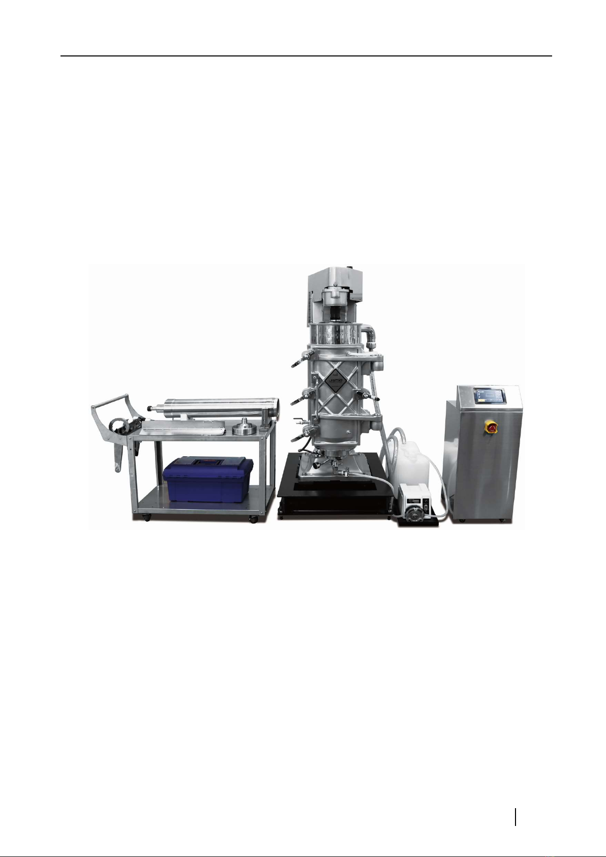
Continuous Centrifuge J1250
Manufacturing company
Hanil Science Industry Co., Ltd.
16, Arayuk-ro, Gochon-eup, Gimpo-si, Gyeonggi-do
www.ihanil.com
packaging unit
1 set including main body, control unit and accessories
The contents of the user manual are subject to change without notice.
© 2022 Hanil Scientific Inc. All rights reserved.
UM-J1250(E)(Rev.1), 2022.09.29
USER MANUAL │ J1250

USER MANUAL │ J1250
CONTENTS
- - - - - - - 6
- - - - - - - 6
- - - - - - 7
- - - - - - 8
1. Precautions for safety
1.1 General safety instructions
1.2 Precautions for use
1.3 Precautions when installing the product
2. Product overview and composition
2.1 Technical Specifications Main Unit
2.2 Technical Specifications Control Unit
2.3 Product composition
2.3.1 Main unit configuration
2.3.2 Accessories
2.4 Configuration for each part
2.4.1 Main unit configuration and dimension
2.4.2 Tool kit and use
2.4.3 Sample feeding pump
2.4.4 Control unit configuration and dimension
- - - - - - 9
- - - - - - - 10
- - - - - 11
-- - - - 12
- - - - - 12
- - - - - 12
- - - - - 13
- - - - - 13
- - - - - 15
- - - - - 18
- - - - - 20
- - - - - 21
- - - - - 21
- - - - - 23
- - - - - 24
- - - - - 24
- - - - - 26
- - - - - 27
- - - - - 27
- - - - - 28
- - - - - 29
- - - - - 30
- - - - - 31
- - - - - 32
- - - - - 34
- - - - - 35
- - - - - 36
- - - - - 37
- - - - - 38
- - - - - 43
HANIL Scientific Inc. │ ihanil.com │Service: +82-2-3452-8966 / [email protected] 4
3.Product installation
3.1 Instrument installation and balancing
3.2 Power Connection
4. How to use the control unit and precautions
4.1 Control panel
4.2 Overall operation flow chart
4.3 Loading screen
4.4 Setting the speed
4.5 Time setting
4.6 Acceleration/deceleration step setting
4.7 History screen
4.8 Saving History
4.9 Saving, Recalling and Deleting Programs
4.10 Start/Stop
4.11 Emergency stop
4.12 Pump Operation
4.13 Operation completion status display
4.14 Setting screen
4.15 Error status display during operation

USER MANUAL │ J1250
CONTENTS
5. Preparing and How to Drive
5.1 Bowl assembly
5.1.1 Insert Teflon sheet
5.1.2 Inserting the triangular rotor blade
5.2 Drag body assembly mounting
5.3 Bowl installation
5.4 Bowl and Motor Spindle fastening
5.5 Things to check before driving
5.6 Driving
- - - - - 44
- - - - - 44
- - - - - 45
- - - - - 46
-- - - - 48
- - - - - 48
- - - - - 50
-- - - - 52
- - - - - 53
- - - - - 54
- - - - - 54
- - - - - 54
- - - - - 55
- - - - - 55
- - - - - 57
6. Disassembly and maintenance
6.1 Disassembly
6.2 Cleaning
6.3 Daily Inspection
6.4 Maintenance
6.5 Bad Code Description
7. Ordering Information - - - - - 58

USER MANUAL │ J1250
1. Precautions for safety
Because this equipment rotates at high speed, the risk of accidents is very high if mishandled. In
order to use the centrifuge effectively and safely, please read the following precautions. Since the
instruction manual is part of the product, always place it around the product.
1.1 General safety instructions
① Before supplying power, remove all packaging materials used to prevent damage during
transportation.
·Install in a dry environment, avoiding high temperature and high humidity.
·Use only cables and devices supplied by the manufacturer. The manufacturer is not responsible
for any problems caused by the user's arbitrary change and use.
·The manufacturer is not responsible for any problems caused by improper operation by the user
outside the range allowed by the device.
·Before use, be sure to check each part to make sure that there is no abnormality in the
centrifuge. In particular, do not use the centrifuge that has been operated by another person
without checking the status.
⑥Do not place near objects such as towels or cloths that may get caught in rotating parts
(Pulley, Spindle, etc.) while driving. It is very dangerous to touch rotating parts, especially with
cotton gloves.
·Do not open the door of the outer bowl frame until the rotation is completely stopped.
·Perform regular inspections on equipment, wiring, and piping.
·If you find a stripped or broken cable, you must replace it immediately.
·Use a suitable electric extension device or power outlet, and do not overload it.
·Do not touch the device, socket outlet or switch with wet hands.
·Do not change the electrical parts of the device or parts.

USER MANUAL │ J1250
1.2 Precautions for use
Since this equipment is used in combination with a high-speed rotating continuous
centrifuge and a control box, it is necessary to familiarize yourself with the precautions for
use of each component.
Please check once more before use.
·Check if any of the necessary parts and devices are missing. (Refer to p12~13, p15~17)
·Check the power supply status and connection wiring conditions between the main body
and the Control Box.
(see p23)
·Since it rotates at high speed, the rotating parts must be well balanced.
·Check if the Serial No. of the body, cap, and triangular rotor blades composing the bowl
match before use. (see p8)
. For the best operation, use the bowl set that matches the serial number of the bowl attached
to the front of the body. (see p8)
·The product installation site must be leveled and firmly fixed on a flat place.
·Check that there is no problem with the wiring connected to the device, and connect the
power cord to the device that requires power.
·Do not place any obstructive objects within 60cm of the device.
·Do not touch or impact the main body while it is operating.
·As this is a device that uses electricity, be careful not to get an electric shock when handling it.
·Do not use flammable, hazardous, or radioactive substances that can generate volatile or
explosive vapors.
·In case of an emergency, operate the emergency switch and open the door after confirming
that the product is stopped. (see p35)
·When not operating the device, turn off the power.
HANIL Scientific Inc. │ ihanil.com │Service: +82-2-3452-8966 / [email protected] 7
USER MANUAL │ J1250
1.3 Precautions when installing the product
1.3.1 Installation
This equipment is installed on a flat concrete floor and is used by balancing it with 6 balancing
feet on the corners of the iron H-beam base at the bottom of the main body. For more reliable
use, it can be operated by driving anchor bolts into the floor. When installing this equipment, it is
recommended to proceed after sufficiently consulting with the technical person in charge of the
manufacturer.
In the installation space, a work space of 60cm or more must be secured on the left, right, and
rear of the equipment, and sufficient space must be secured in the front.
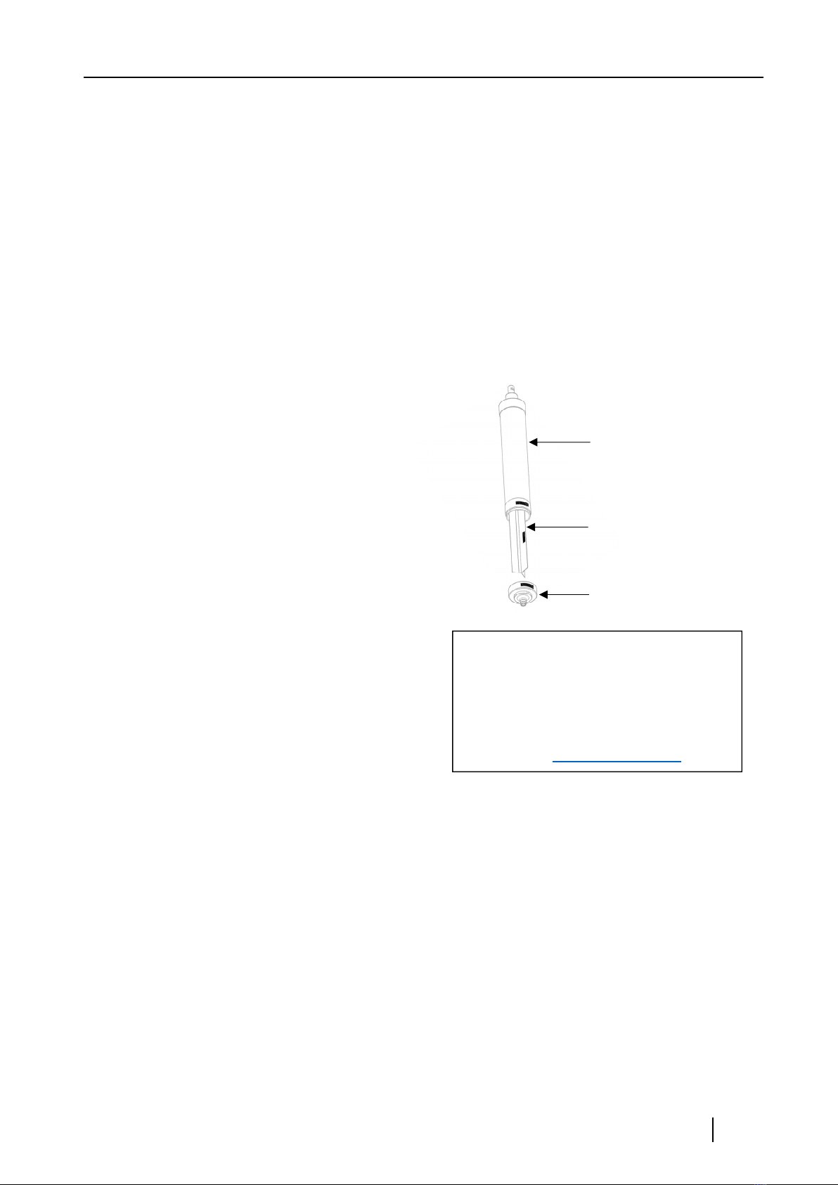
Bowl body
> > Precautions
Bowl configuration and configuration with the main body
-Serial No. is engraved on each of the 3 parts of
the bowl as shown in the picture on the right.
-Bowls must be configured in one set
with the same Serial No. for the best
operation, so never mix them.
-The sticker shown on the right is attached to
the outer surface of the main body, and the
Serial No. Use bowl sets from xxxxxx.
Triangular rotor blades
bowl cap
/ WARNING /
For optimal use, this product
Serial No. xxxxxx Bowl Setwith
use it.
inquiry :[email protected]
1.3.2 Electrical installation work
This equipment requires a 3-phase 4-wire 380V power supply, so electrical work is required
before installation.
-The control unit should be located where it is easy to operate.
-For electrical wiring and outlet specifications, be sure to inquire with the manufacturer
before installing the power supply.
1.3.3 Flexible tube
-Use flexible tube for piping for feed sample.
-If the supply pipe and sample collection container are located in the front, it may cause
inconvenience to work and movement, so be sure to place them on the left or right side.
-Select and use a pump suitable for the supply pressure. (Refer to p18~19)

USER MANUAL │ J1250
2. Product overview and composition
This equipment is for separating the supernatant, which is the liquid part of the sample, and
the sludge, which is the solid part, so that it is suitable for the process needs such as sample
precipitation, filtration and washing. designed.
Due to the long tube-shaped rotor, the distance through which the mixed solution injected
from the lower part of the rotor passes until it is centrifuged and discharged is long and receives
the effect of strong centrifugal force for a relatively long time, so the centrifugation of the mixed
solution is very good This can reduce process time and increase productivity compared to
general centrifugation methods.
-Tubular type industrial centrifuge for continuous sample separation
-Two phase separation of liquid and solid
-High recovery of sludge (cake type)
-Water jacketed cooling system (optional)
-Premium quality stainless steel bowl
-Intuitive 7” touch-screen control
-Accurate control of speed through inverter
-Speed control from 1,000 to 15,000 RPM
-Distinctive emergency stop switch
-During operation, the door open sensor is detected and the motor is automatically stopped
with an error phrase.
-The three-color blinking light can recognize normal operation status or emergency abnormal
situation; green for normal, yellow for standby status, and red for errors and emergency.

USER MANUAL │ J1250
2.1 Technical Specifications - Main Unit
Functions
main unit
Motor
Specification
Power 380V 3.7kW (3-phase)
Tubular Bowl
Net Capacity (L) / Weight (kg)
Dimension (inner/outer)
Material
Sample Collection Sheet
Sample Feeding pump
Frame and Door, Material
Frame Base
Trolley for Bowl and Tools
Dimensions (With Base)
Dimensions (W x D x H, mm)
with H-beam base
without pump or trolley
Net Weight
with bowl & H-beam base
without pump or trolley
9/27
157(Φ) x 142(Φ) x 960(L) mm
Stainless Steel 316L
Teflon with a dimension of 733x395x0.4 mm
Peristaltic Tubing Pump (WT600-2J)
Powder-painted Steel
(optional) Stainless steel 304
(optional) Water-jacketed
Powder-painted Steel H-beam with 4
wheels and 6 balancing foot
Stainless steel trolley with tools in a box
860(W) x 1085(D) x 1900(H) : Door closed
860(W) x 1430(D) x 1900(H) : Door open
564 kg
HANIL Scientific Inc. │ ihanil.com │Service: +82-2-3452-8966 / [email protected] 10

USER MANUAL │ J1250
2.2 Technical Specifications - Control Unit
Functions
control unit
Specification
display screen
speed control
Max. RCF
ACC/DEC ramps
program memory
Time control
data transport
History tracking
Inverter control
Pump control
Safeties
Actual speed sensing
Door close/open sensing
Emergency Stop switch
foot switch
Level sensor 1, 2
Dimensions (W x D x H mm)
7” wide touch (Capacitive type)
1,000 to 15,000 RPM
15,801 xg (Radius: 62.814 mm)
3/4
99
< 100 hours
Yes (USB port)
Yes
3P4W 380V, 7.5KW
Selectable, auto or manual
Yes
Yes
Yes
Optional
Optional
405x 460 x 1310 (incl. warning light)
Weight
without cables 47 kg
HANIL Scientific Inc. │ ihanil.com │Service: +82-2-3452-8966 / [email protected] 11
USER MANUAL │ J1250
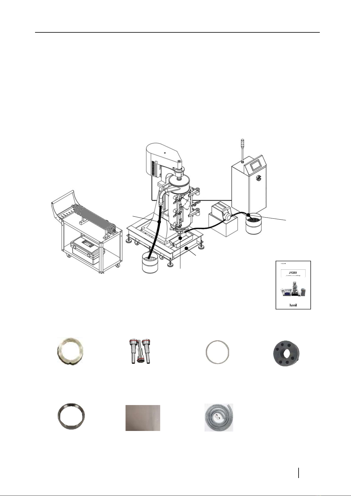
2.3 Product composition
2.3.1 Main unit configuration
It is a tubular type continuous centrifuge and consists of a driving motor, a frame, a
door, an H-beam base, and a bowl, a high-speed rotating chain. is supplied with
Motor
control unit
main unit
Trolley Power
Cable
Bowl
Hose Tube
sample feeding pump,
Tube & rack
H-beam base
tool kit
(p15~17) filtrate tray
Operation
manual
2.3.2 Accessories
Drag bushings,
2ea
Inlet Nozzles(3,4,5Ø),
3ea
Bowl cap sealing
gasket, 2ea
rubber coupling,
2ea
Bowl cap nut
2ea
Teflon Sheet, 3 sheets
735x395x0.35 (W x L x T, mm)
Outlet Hose(1m)
HANIL Scientific Inc. │ ihanil.com │Service: +82-2-3452-8966 / techsupport@ihanil. com 12

USER MANUAL │ J1250
2.4 Configuration for each part
2.4.1 Main unit configuration and dimensions
[Main part name]
2
96-1
3
4
814
7
6
1
15
14
5
13 12
10 16
11
1. Frame 2. Motor 3. Drive motor cover
4. Pulley Flange 5 . Drag Body Assembly 6. Door
6-1. water jacket door
(optional) 7. Supernatant Outlet 8. Supernatant Outlet Lid
9. Balancing window 10. Base, steel 11. Balancing foot with nut 6 set
12. Sample in gate 13. Wheel 14. Bowl
15. Trolley 16. Tool kit
HANIL Scientific Inc. │ ihanil.com │Service: +82-2-3452-8966 / [email protected] 13

USER MANUAL │ J1250
[Main unit dimensions, mm]
Front
Right Left
HANIL Scientific Inc. │ ihanil.com │Service: +82-2-3452-8966 / [email protected] 14
USER MANUAL │ J1250
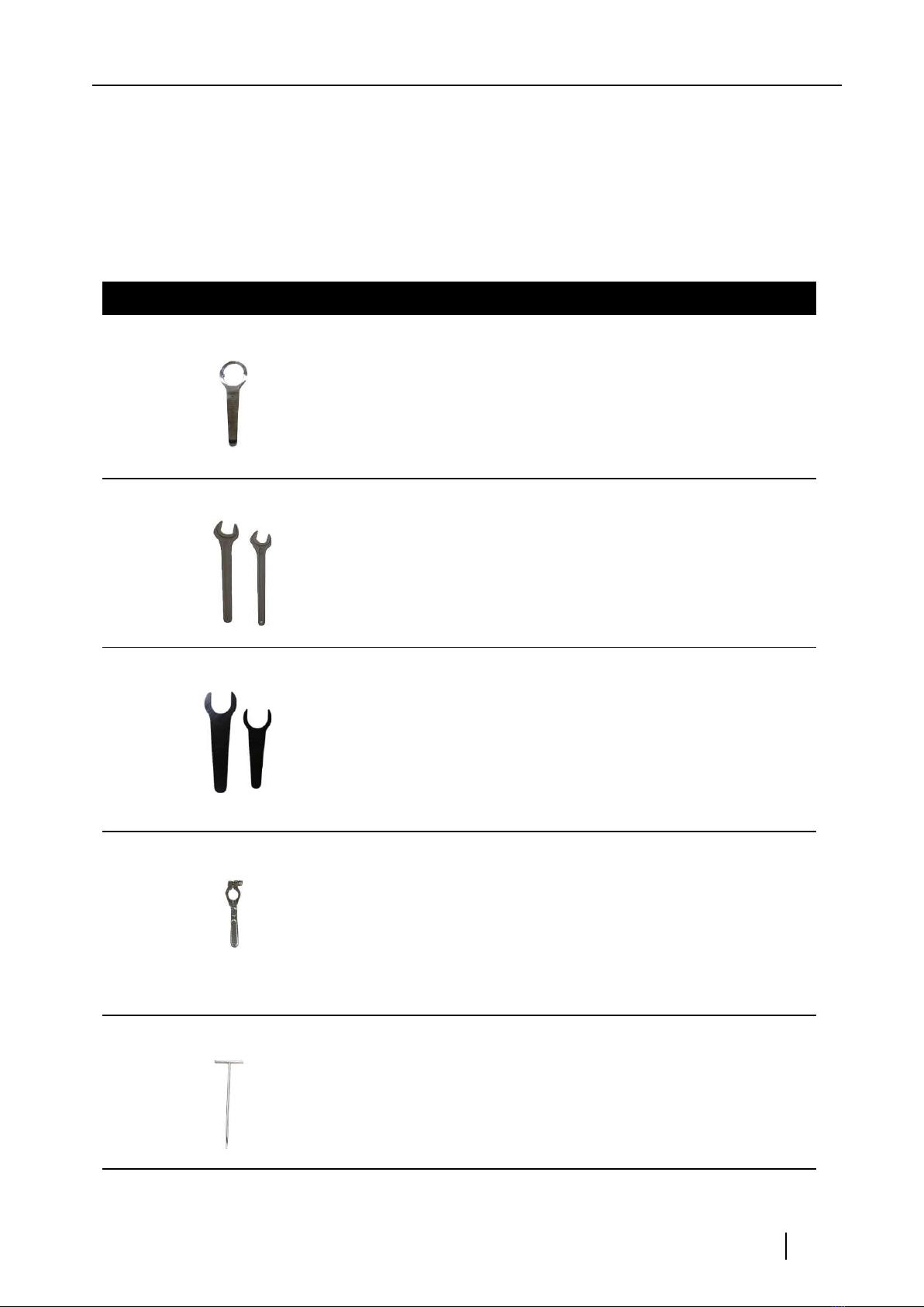
2.4.2 Tool kit and use
[Bowl assembly & Disassembly tools]
No. Photo Name Purpose
1Bowl wrench bowl cap open and close
22 Coupling
wrenches
Bowl spindle assembly and
disassembly
61mm: for disassembling and
assembling the pulley sleeve
54mm: for disassembling and
assembling the bearing pulley
32 Pulley wrenches
Bowl boss
sleeve
wrench
4Bow cap nut disassembly and assembly
5hook spanner For triangular wing separation
USER MANUAL │ J1250
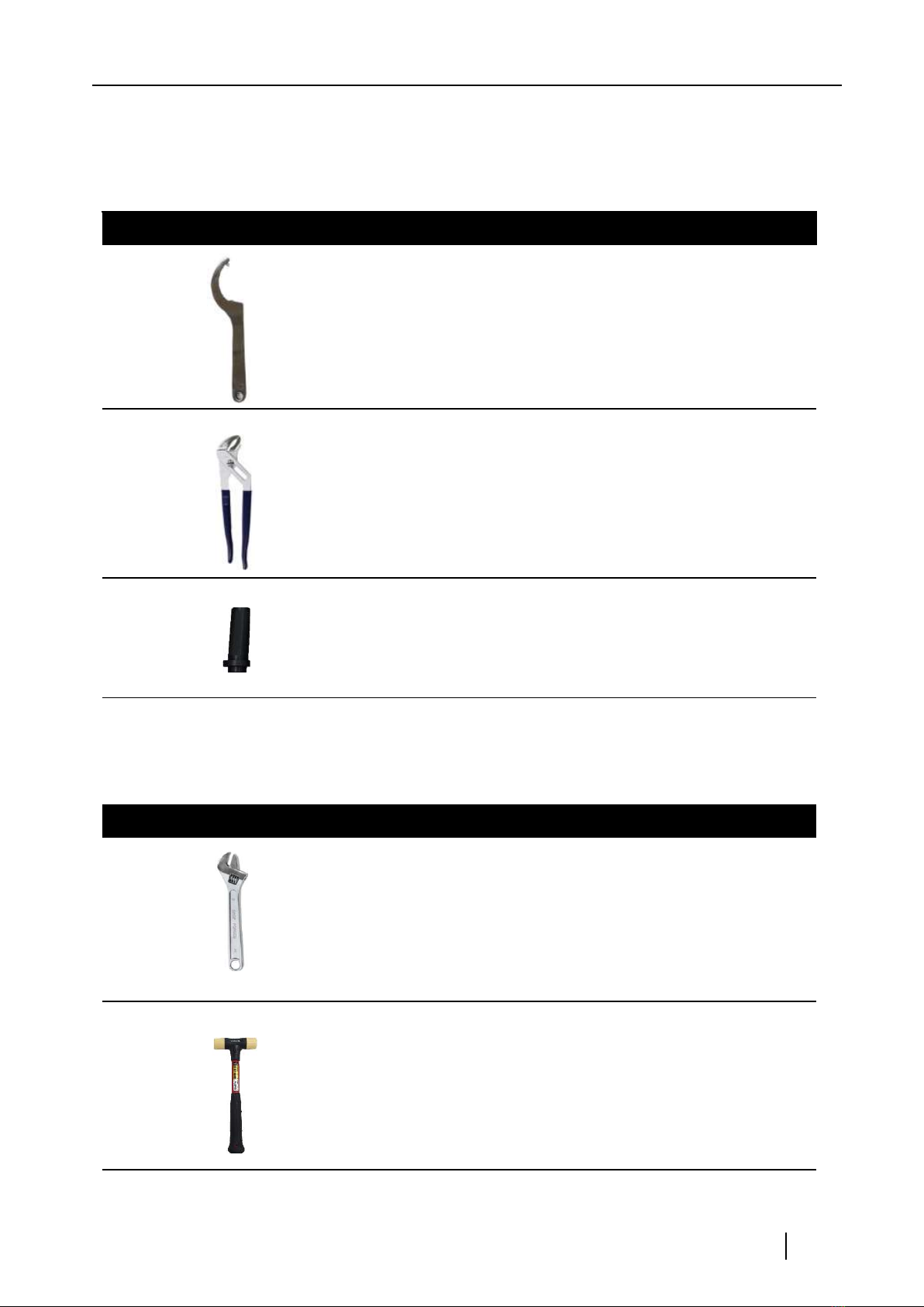
[Drag Assembly & Disassembly Tools]
1Drag wrench Drag shell disassembly and assembly
For disassembling and
assembling the parallel cap
For disassembly and assembly of
sample receiving hose nipple
2Pliers
3Drag bushing tool Drag bushing disassembly and assembly
[General Tools] - 1
Drain pipe, grease, elbow, motor fixing
bolt, cover fixing bolts, other assembly
and disassembly
1Monkey wrench
For bowl, drag assembly, and drag hand
nut separation and fastening
Opening and closing the door
2Urethane hammer
No. Photo Name Purpose
No. Photo Name Purpose
USER MANUAL │ J1250
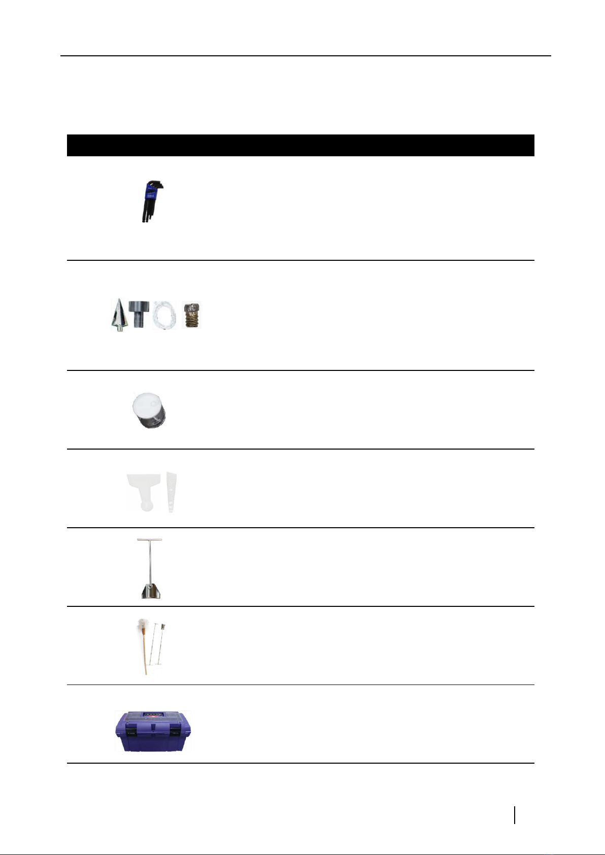
[General Tools] - 2
1.5~10,0mm 9 types
Used to open and close the bowl cap
3L-wrench
4Balancing tool set Tools for body balancing
Lubrication between bowl cap nut and
drag bushing
5Grease
For grease replenishment, Teflon
sheet, and sludge separation
62 Specials
For separating bowl and Teflon
sheet For sludge separation
7Bowl cleaner
Bowl cleaning tools
3 types
8Bowl cleaning tool
9Tool box Tool storage
HANIL Scientific Inc. │ ihanil.com │Service: +82-2-3452-8966 / [email protected] 17
No. Photo Name Purpose

USER MANUAL │ J1250
2.4.3 Sample feeding pump
: WT600-2J Basic peristaltic tubing pump
Speed
speed resolution
speed accuracy
output torque
60~600 rpm, CW/CCW
1 rpm
<±1%
≥1.50N·M
Control panel, external signal control and
communication control available
control mode
Display 3-digit LED displays current speed
Start/stop, cw/ccw control
speed control; 4 to 20 mA, 0.5 to 5 V, 1 to 10 V, 1 to 10 KHz
external control
power supply
Power consumption
Operating condition
AC 176-264V 50/60Hz
≤200W
Temperature; 0~40℃
relative humidity; <80%
285 L x 207 W x 180 H /mm
5.2 kg
IP31
Dimensions
Weight
IP rating
USER MANUAL │ J1250
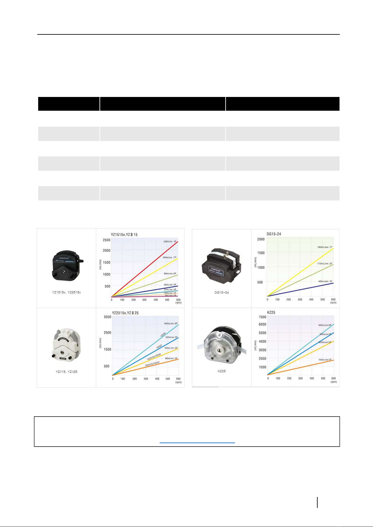
[Pump head and Tube selection guide]
pump head Tubing Flow rates (mL/min)
YZ1515 # 13, 14, 19, 16 25, 17, 18 4 to 2,200
YZ2515 #15, 24 100 to 1,600
YZII15 # 13, 14, 19, 16, 25, 17, 18 4 to 2,200
YZII25 #15, 24, 35, 36 100 to 3,000
DG15-24 #16, 25, 17 500 to 1,800
KZ25 #15, 24, 35, 36 200 to 6,000
When ordering a pump, please order the pump head & tubing according to the conditions.
inquiry :[email protected]

USER MANUAL │ J1250
2.4.4 Control unit composition and Dimensions
Emergency Stop switch power switch
Operation status indicator
7” Display LCD Screen - Stop
- Running : Green
- Alarm : Red
: Yellow
USB Port Imbal Door Foot RS232
Temp L1 L2
Ext. conn
Pump Conn.
Spare Conn
Motor Cable Conn.
Power Cable Conn.
back side
front side right side
Other manuals for J1250
1
Table of contents
Other Hanil Laboratory Equipment manuals


Hanil
Hanil Ultra 5.0 User manual

Hanil
Hanil FLETA 40P User manual

Hanil
Hanil Micro 12 User manual

Hanil
Hanil Smart R17 User manual

Hanil
Hanil T04B User manual

Hanil
Hanil J1250 User manual

Hanil
Hanil M 13 User manual

Hanil
Hanil Component R6 User manual

Hanil
Hanil Fleta 5 User manual

Hanil
Hanil Fleta5 User manual


Popular Laboratory Equipment manuals by other brands


Streck
Streck ESR-Auto Plus 504-V9 manual

Ameson
Ameson MINI AIR PRO user manual

TOSOH BIOSCIENCE
TOSOH BIOSCIENCE TSKgel HPLC Column instruction manual

10x Genomics
10x Genomics Chromium Controller Readiness Test manual

PHI
PHI VersaProbe Operations

BioSpec Products
BioSpec Products Mini-BeadBeater 96 user manual


