Newport M-/IMS100V User manual
High-Performance Linear S ages
for Ver ical Use
IMS-V Series
USER’SMANUAL
G
U
A
R
A
N
T
E
E
D
S
P
E
C
I
F
I
C
A
T
I
O
N
S

EDH0211En1051 — 12/18 ii
IMS-V Series High-Performance Linear S ages for Ver ical Use
Warranty
Newpor Corpora ion warran s his produc o be free from defec s in
ma erial and workmanship for a period of 1 year from he da e of
shipmen . If found o be defec ive during he warran y period, he produc
will ei her be repaired or replaced a Newpor ’s discre ion.
To exercise his warran y, wri e or call your local Newpor represen a ive,
or con ac Newpor headquar ers in Irvine, California. You will be given
promp assis ance and re urn ins ruc ions. Send he ins rumen ,
ranspor a ion prepaid, o he indica ed service facili y. Repairs will be
made and he ins rumen re urned, ranspor a ion prepaid. Repaired
produc s are warran ed for he balance of he original warran y period, or
a leas 90 days.
Limitation of Warranty
This warran y does no apply o defec s resul ing from modifica ion or
misuse of any produc or par .
CAUTION
Please ret rn eq ipment in
the original (or eq ivalent)
packing.
Yo will be responsible for
damage inc rred from
inadeq ate packaging if the
original packaging is not
sed.
CAUTION
Warran y does no apply o damages resul ing from:
• Incorrec usage:
– Load on he s age grea er han maximum specified load.
– Carriage speed higher han specified speed.
–Improper grounding.
¬ Connec ors mus be properly secured.
¬ When he load on he s age represen s an elec rical risk, i mus
be connec ed o ground.
– Excessive or improper can ilever loads.
• Modifica ion of he s age or any par hereof.
This warrant is in lieu of all other warranties, expressed or implied,
including an implied warrant of merchantabilit or fitness for a
particular use. Newport Corporation shall not be liable for an indirect,
special, or consequential damages.
b Newport Corporation, Irvine, CA. All rights reserved.
Original instructions.
No part of this document ma be reproduced or copied without the prior
written approval of Newport Corporation. This document is provided for
information onl , and product specifications are subject to change without
notice. An change will be reflected in future publishings.
© 2018

iii EDH0211En1051 — 12/18
IMS-V Series High-Performance Linear S ages for Ver ical Use
Table of Contents
Warranty .................................................................................................................ii
EC Declaration of Conformity...............................................................................v
Definitions and Symbols.......................................................................................vi
Warnings ...............................................................................................................vii
Caution .................................................................................................................viii
1.0 — Introduction.................................................................................1
2.0 — Description ...................................................................................2
2.1 Design Details ............................................................................................2
3.0 — Characteristics............................................................................3
3.1 Definitions..................................................................................................3
3.2 Mechanical Specifications .......................................................................4
3.3 Load Specification Definitions.................................................................4
3.4 Load Characteristics and Stiffness .........................................................5
3.5 Stage Weights ............................................................................................5
4.0 — Drives and Motors ....................................................................6
4.1 DC-Servo Drive Version ............................................................................6
4.2 Sensor osition..........................................................................................6
4.3 Feedback Signal osition .........................................................................7
4.4 inouts........................................................................................................8
4.5 MCAB-5 Cable ............................................................................................8
5.0 — Connection to Newport Controllers................................9
5.1 Warnings on Controllers ..........................................................................9
5.2 Connection to X S Controller ...............................................................10
5.3 Connection to ES 301 Controller..........................................................10
5.4 Connection...............................................................................................10
5.5 Cables .......................................................................................................10
6.0 — Connection to Non-Newport Electronics ....................11
6.1 Connections.............................................................................................11
7.0 — Dimensions.................................................................................12
7.1 (M-)IMS-V Stages .....................................................................................12
7.2 Top late Interface..................................................................................13
7.3 (M-)IMS-V Stages without Top late Interface.....................................13

EDH0211En1051 — 12/18 iv
IMS-V Series High-Performance Linear S ages for Ver ical Use
8.0 — Maintenance ..............................................................................14
8.1 Maintenance ............................................................................................14
8.2 Repair .......................................................................................................14
8.3 Calibration ...............................................................................................14
Service Form .........................................................................................................15

v EDH0211En1051 — 12/18
IMS-V Series High-Performance Linear S ages for Ver ical Use
IMS-V Series
EU Declaration of Conformity
following Annex II-1A
of Directive 2006/42/EC on machinery
The manufacturer:
MICRO-CONTROLE Spectra-Physics,
9, rue du bois sauvage
F-91055 Evry FRANCE
Hereby declares that the machinery:
yDescription: " IMS-V "
yFunction: High-Performance Linear Stages for Vertical Use
yModels: M-/IMS100V, M-/IMS300V
– the technical file of which was compiled by:
Mr Hervé LE COINTE , Quality Director,
MICRO-CONTROLE Spectra-Physics, Zone Industrielle - B.P.29
F-45340 Beaune La Rolande France
– complies with all the relevant provisions of the Directive 2006/42/EC on machinery.
– complies with all the relevant provisions of the Directive 2014/30/EU relating to electro-
magnetic compatibility.
– complies with all the relevant provisions of the Directive 2011/65/EU relating to RoHS2.
– was designed and built in accordance with the following harmonised standards:
yNF EN 61326-1:2013 « Electrical equipment for measurement, control and
laboratory use – EMC requirements – Part 1: General requirements »
yNF EN 55011:2010/A1:2011 Class A
– was designed and built in accordance with the following other standards:
yNF EN 61000-4-2
yNF EN 61000-4-3
yNF EN 61000-4-4
yNF EN 61000-4-5
yNF EN 61000-4-6
ORIGINAL DECLARATION
Done in Beaune La Rolande on 16 May 2017
Hervé LE COINTE
Quality Director
DC1-EN rev:A
EC Declaration of Conformity
EDH0211En1051 — 12/18 vi
IMS-V Series High-Performance Linear S ages for Ver ical Use
Definitions and Symbols
The following erms and symbols are used in his documen a ion and also
appear on he produc where safe y-rela ed issues occur.
General Warning or Caution
The exclama ion symbol may appear in warning and cau ion ables in his
documen . This symbol designa es an area where personal injury or
damage o he equipmen is possible.
The following are defini ions of he Warnings, Cau ions and No es ha may
be used in his manual o call a en ion o impor an informa ion regarding
personal safe y, safe y and preserva ion of he equipmen , or impor an
ips.
WAR N I N G
Warning indicate a potentially dangerou ituation which can re ult in
bodily harm or death.
CAUTION
Caution indicate a potentially hazardou ituation which can re ult in
damage to product or equipment.
NOTE
Note indicate additional information that mu t be con idered by the
u er or operator.
European Union CE Mark
The presence of he CE Mark on Newpor Corpora ion equipmen means
ha i has been designed, es ed and cer ified as complying wi h all
applicable European Union (CE) regula ions and recommenda ions.
Warning and Caution
ATTENTION
Thi tage i a Cla A device. In a re idential environment, thi device
can cau e electromagnetic interference. In thi ca e, uitable mea ure
mu t be taken by the u er.
vii EDH0211En1051 — 12/18
IMS-V Series High-Performance Linear S ages for Ver ical Use
Warnings
WARNING
The motion of objects of all types carries potential risks for operators.
Ensure the protection of operators by prohibiting access to the dangerous
area and by informing the personnel of the potential risks involved.
WAR N I N G
D n t use this stage when its m t r is emitting sm ke r is unusually
h t t the t uch r is emitting any unusual d r r n ise r is in any
ther abn rmal state.
St p using the stage immediately, switch ff the m t r p wer and then
disc nnect the electr nics p wer supply.
After checking that sm ke is n l nger being emitted c ntact y ur
Newp rt service facility and request repairs. Never attempt t repair the
stage y urself as this can be danger us.
WAR N I N G
Make sure that this stage is n t exp sed t m isture and that liquid d es
n t get int the stage.
Nevertheless, if any liquid has entered the stage, switch ff the m t r
p wer and then disc nnect the electr nics fr m p wer supply.
C ntact y ur Newp rt service facility and request repairs.
WAR N I N G
D n t insert r dr p bjects int this stage, this may cause an electric
sh ck, r l ck the drive.
D n t use this stage if any f reign bjects have entered the stage.
Switch ff the m t r p wer and then disc nnect the electr nics p wer
supply.
C ntact y ur Newp rt service facility f r repairs.
WAR N I N G
D n t place this stage in unstable l cati ns such as n a w bbly table r
sl ping surface, where it may fall r tip ver and cause injury.
If this stage has been dr pped r the case has been damaged, switch ff
the m t r p wer and then disc nnect the electr nics p wer supply.
C ntact y ur Newp rt service facility and request repairs.
WAR N I N G
D n t attempt t m dify this stage; this may cause an electric sh ck r
d wngrade its perf rmance.
WAR N I N G
D n t exceed the usable depth indicated n the m unting h les (see
secti n “Dimensi ns”). L nger screws can damage the mechanics r
cause a sh rt-circuit.

EDH0211En1051 — 12/18 viii
IMS-V Series High-Performance Linear S ages for Ver ical Use
Caution
CAUTION
Do not place this stage in a hostile environment such as X-Rays, har
UV,… or in any vacuum environment.
CAUTION
Do not place this stage in a location affecte by ust, oil fumes, steam or
high humi ity. This may cause an electric shock.
CAUTION
Do not leave this stage in places subject to extremely high temperatures
or low temperatures. This may cause an electric shock.
• Operating temperature: +10 to +35 °C
• Storage temperature: -10 to +40 °C (in its original packaging)
CAUTION
Do not move this stage if its motor power is on.
Make sure that the cable to the electronics is isconnecte before
moving the stage. Failure to o so may amage the cable an cause an
electrical shock.
CAUTION
Be careful that the stage is not bumpe when it is being carrie . This
may cause it to malfunction.
CAUTION
When han ling this stage, always unplug the equipment from the power
source for safety.
CAUTION
When the carriage is in its en -of-run position, it is strongly recommen e
not to go beyon this point as this may amage the stage mechanism.
CAUTION
Contact your Newport service facility to request cleaning an
specification control every year.
1 EDH0211En1051 — 12/18
IMS-V Series High-Performance Linear S ages for Ver ical Use
High-Performance Linear S ages
for Ver ical Use
IMS-V Series
1.0 —Introduction
This manual provides operating instructions for the stage that you have
purchased in the IMS-V Series:
IMS-V Series li ear stages: 100 a d 300 mm travel ra ges.
RECOMMENDATION
We recommend you read carefully the chapter “Connection to
electronics” before using the (M-)IMS-V stage.

EDH0211En1051 — 12/18 2
IMS-V Series High-Performance Linear S ages for Ver ical Use
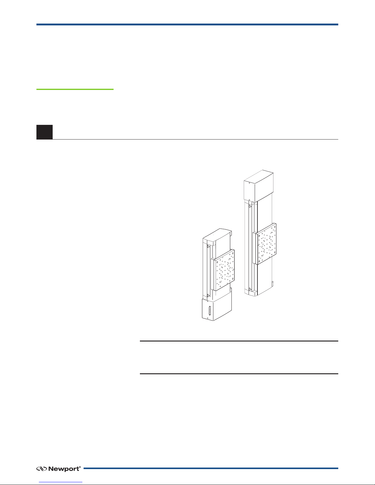
2.0 —Description
The IMS-V Series linear stage complements the (M-)IMS Series by providing
linear travel ranging of 100 and 300 mm. The stages feature robust designs
with high performance but without high cost, making them cost-effective
solutions for precision industrial and laboratory applications.
Using the same industry-proofed technology as the (M-)ILS Series, the
IMS-V Series features a FEM optimized, aluminum extruded body that is
highly stiff, while minimizing the bending effect caused by different
thermal expansion coefficients of the aluminum body and the steel rails.
Smooth running recirculating ball bearing slides with ball separators
provide accurate linear motion and avoid ball cage migration found on
linear ball bearings or crossed roller bearings.
A highly-stiff, backlash-free, 3 mm pitch friction lead screw ensures
vertical movement with capability to handle high payload.
For more demanding precision positioning requirements, the IMS-V Series
is equipped with a highly interpolated linear scale providing 0.1 µm
resolution feedback.
The completely closed design of the IMS-V Series with an upper rigid
cover, underlining its robustness and long lasting values. IMS-V stages also
feature a motor side mounted origin for repeatable initialization, limit
switches to prevent over travel, and elastomeric end-of-run dampers for
smooth emergency braking.
For optimal performance, we recommend the use of our motion
controllers to choose in accordance with the payload.
The IMS-V stages are supplied with a 5-meter cable for connection to our
motion controllers.
2.1 Design Details
Base Material Extruded Aluminum
Bearings Four way equal loaded caged recirculating ball bearings
Drive Mechanism Precision ground 16 mm diameter lead screw,
High-wear resistance polyethylene terephthalate nut, no preload
Drive Screw Pitch (mm) 3
Feedback Linear steel scale, 20 µm signal period, 0.1 µm resolution
Limit Switches Optical
Origin Optical, approx. 8 mm from motor side limit
Motor DC servo
Cable 5 m long motor cable included
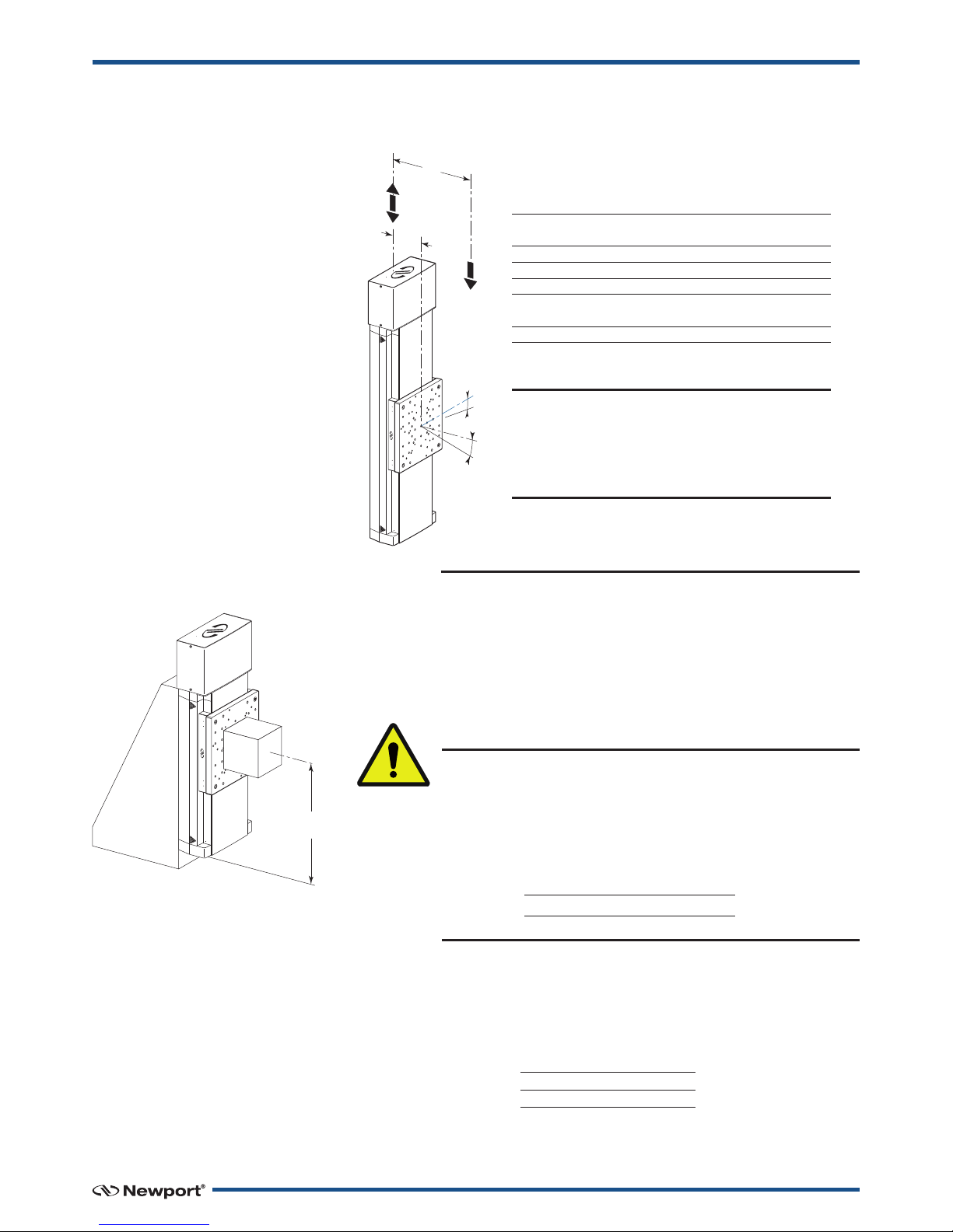
The EQ180 bracket must be
used with a stage:
• (M-)IMS100V whe
payload is ≤500 N;
• (M-)IMS300V whe
payload is ≤100 N.

3 EDH0211En1051 — 12/18
IMS-V Series High-Performance Linear S ages for Ver ical Use
3.0 —Characteristics
3.1 Definitions
Specificatio s of our products are established i refere ce to ISO 230
sta dard part II “Determi atio of accuracy a d repeatability of
positio i g umerically co trolled axes”.
This sta dard gives the defi itio of positio u certai ty which depe ds
o the 3 followi g parameters:
Absolute Accuracy
Differe ce betwee ideal positio a d real positio .
Accuracy
Differe ce betwee ideal positio a d real positio after the compe satio
of li ear errors.
Li ear errors i clude: cosi e errors, i accuracy of screw or li ear scale
pitch, a gular deviatio at the measuri g poi t (Abbe error) a d thermal
expa sio effects. All Newport motio electro ics ca compe sate for
li ear errors.
The relatio betwee absolute accuracy a d o -axis accuracy is as follows:
Absolute Accuracy = Accuracy + Correction Factor xTravel
Repeatability
Ability of a system to achieve a comma ded positio over ma y attempts.
Reversal Value (Hysteresis)
Differe ce betwee actual positio values obtai ed for a give target
positio whe approached from opposite directio s.
Minimum Incremental Motion (MIM or Sensitivity)
The smallest i creme t of motio a device is capable of deliveri g
co siste tly a d reliably.
Resolution
The smallest i creme t that a motio device ca theoretically move
a d/or detect. Resolutio is ot achievable, whereas MIM, is the real
output of a motio system.
Yaw, Pitch
Rotation of carriage around the Z axis (Yaw) or Y axis (Pitch), when it
moves.
The testing of accuracy, repeatability, and reversal error are made
systematically with test e uipment in controlled environment (20 ±1 °C).
A linear cycle with 21 data points on the travel and 4 cycles in each
direction gives a total of 168 points.
Guaranteed and Typical Specifications
Guaranteed maximum performance values are verified per Newport's A167
metrology test procedure. For more information, please consult the
metrology tutorial section in the Newport catalog or at www.newport.com

EDH0211En1051 — 12/18 4
IMS-V Series High-Performance Linear S ages for Ver ical Use
3.2 Mechanical Specifications
CAUTION
To reach specifications stated, stages must be fixed on a plane surface
with a flatness of 5 µm.
3.3 Load Specification Definitions
(Depends on the Controller)
CAUTION
To go over the indicated speed in accordance with the
payload may damage the stage mechanism.
Axial Load Capacity (±Cx)
Maximum load along the direction of the drive train.
Off-Centered Load (Q)
Maximum cantilever-load a stage can move: QV≤1500 ÷ (1 + D/90), but not
greater than Cx Max.
D: Cantilever distance.
G
U
A
R
A
N
T
E
E
D
S
P
E
C
I
F
I
C
A
T
I
O
N
S
IMS100V IMS300V
Travel Range (mm) 100 300
Minimum Incremental Motion (µm) 0.3 µm with XPS,
0.6 µm with ESP301 or SMC100CC
Uni-directional Repeatability, Typical (Guaranteed) (µm) ±0.10 (±0.25) ±0.12 (±0.25)
Bi-directional Repeatability, Typical (Guaranteed) (1) (µm) ±0.15 (± 0.50) ±0.20 (± 0.50)
Accuracy, Typical (Guaranteed) (1) (µm) ±0.6 (±2.0) ±3.5 (±5.0)
Maximum Speed 20 mm/s with up to 100 load
5 mm/s with higher loads
Pitch, Typical (Guaranteed) (1) (2) (µrad) ±15 (±50) ±35 (±125)
Yaw, Typical (Guaranteed) (1) (2) (µrad) ±10 (±38) ±20 (±75)
MTBF 20,000 h with 300 load and with a 10% duty cycle
1) Fo the definition of Typical and Gua anteed specifications see “Motion Basics Te minology & Standa ds” Tuto ial
at www.newpo t.com
2) To obtain a csec units, divide µ ad value by 4.8.
Payloa (N)
100 400
Specified Speed (1) (mm/s) 20 5
Specified Acceleration (mm/s2) 80 20
1) The va iation of the speed is linea between 100 N and 400 N.
Load on Carriage (N)
Maximum Speed vs Payload
0
5
10
15
20
0 40 100 200 300 400
Speed (mm/s)
5 EDH0211En1051 — 12/18
IMS-V Series High-Performance Linear S ages for Ver ical Use
3.4 Load Characteristics and Stiffness
WARNING
Because of the use of a friction lead screw and the stick-slip
effect, the sensitivity of (M-)IMS-V stages at full load
depends a lot on the controller/driver features and tuning.
Back and forth motions of a few counts after settling are
normal. The self locking of the lead screw allow to turn off
the servo loop to stop these oscillations, without getting
unwanted motion.
WARNING
To reach the specifications stated for a (M-)IMS-V stage, the
mounting bracket or the fastening support of the stage must
have a minimum stiffness at the level of the load in top
position, as indicated below:
Max. Min.
load stiffness
100 N 5 N/µm
400 N 10 N/µm
3.5 Stage Weights
Weights indicated into the below table are average values for stages with a
typical drive unit installed.
66
D
+Cx
–Cx
QV
kαz
kαy
Min. -Cx; +Cx 40
Max. -Cx; +Cx 400 with XPS
100 with ESP301
kay, Compliance in pitch 0.2 µrad/ m
kaz, Compliance in yaw 1 µrad/ m
QV, Off-center load QV≤1500 ÷ (1 + D/90)
D, Cantilever distance in mm between the center of mass of the load and
the bearings center.
Distance between top surface and the bearings center 66 mm
NOTES
1. The vertical load must be within the axial Cx, and
cantilevered, QVload limit.
2. Motor down orientation is preferred for easier tuning.
3. Minimum preload is required.
Weight [lb (kg)]
(M-)IMS100V 30.0 (13.6)
(M-)IMS300V 37.5 (17.0)
TOP
POSITION
EDH0211En1051 — 12/18 6
IMS-V Series High-Performance Linear S ages for Ver ical Use
4.0 —Drives and Motors
4.1 DC-Servo Drive Version
A DC-motor and a linear steel scale, 20 µm signal period, 0.1 µm resolution.
DC-Motor erformance Specifications and Characteristics
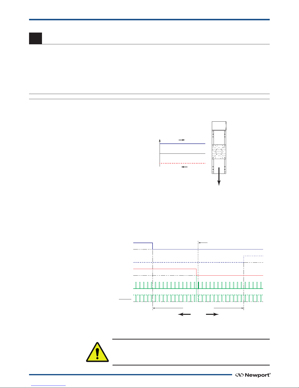
Command Signals for the DC-Motor
In the above drawings, + Motor signal is referred to – Motor signal.
➀When the stage moves in + Direction, the + Motor voltage is higher than
– Motor voltage.
➁When the stage moves in – Direction, the + Motor voltage is lower than
– Motor voltage.
4.2 Sensor osition
End-of-Run and Mechanical Zero are 5 V open collector type.
The Index ulse provides a repeatable Home osition at ±1 step.
CAUTION
“End-of-Run” and “Mechanical Zero” are active signals and should not be
connected to any other source.
Resolution Spee Nominal Max RMS Max. Peak Resistance In uctance Tachometer
(µm) (mm/s) Voltage (V) Current (A) Current (A) (Ω) (mH) Const. (V/krpm)
IMS-V 0.1 20 (1) 48 1.5 2.3 5.1 3.2 –
1) With up to 100 N load.
+V
+ Motor
– Motor –V
MOTION Direction +
MOTIONDirection –
Direction +
– EOR Limit
Mechanical
Zero
Stage Travel Range
Index Pulse
Index Pulse
+ EOR Limit
Home Position (Origin)
at Center of Travel Range
Direction – MOTION Direction +

7 EDH0211En1051 — 12/18
IMS-V Series High-Performance Linear S ages for Ver ical Use
4.3 Feedback Signal osition
The incremental sensor consists of an optical scale and an encoder head.
When the carriage moves, the encoder head generates square signals in
quadrature and sends to pins #19, #20, #23 and #24 of the SUB-D25
connector.
“Encoder” and “Index ulse” are “differential pair” (type RS-422) type
output signals. Using these signals permits a high immunity to noise.
Emission circuits generally used by Newport are 26LS31 or MC3487.
Reception circuits to use are 26LS32 or MC3486.
0
1
Encoder
Phase A
0
1
Encoder
Phase A
1234
0
1
Encoder
Phase B
0
1
Encoder
Phase B
Direction – MOTION Direction +
Direction +
SUD-D25 OR SUB-D15
Encoder Phase A 19 13
Encoder Phase A 23 6
Encoder Phase B 20 14
Encoder Phase B 24 7
Index Pulse Phase I 15 15
Index Pulse Phase I 25 8
21 12
22 5
NEWPORT
STAGE USER
CONNECTOR PIN #
Output Signals
Encoders
& Sensors
Power Supply
+5 V 5%
150 mA max.
0 V
}
EDH0211En1051 — 12/18 8
IMS-V Series High-Performance Linear S ages for Ver ical Use
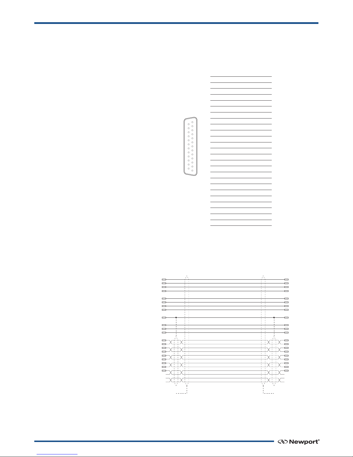
4.4 inouts
The pinout diagram for the IMS-V stages SUB-D25M connector is shown
below.
4.5 MCAB-5 Cable
A 5-meter MCAB-5 cable is supplied with each IMS-V stage (see section 5.5:
”Cables”).
13
25
141
IMS-V
1 N.C.
2 N.C.
3 N.C.
4 N.C.
5 + Motor
6 + Motor
7 – Motor
8 – Motor
9 N.C.
10 N.C.
11 N.C.
12 N.C.
13 Mechanical Zero
14 Groun
15 In ex Pulse I
16 0 V
17 + En -of-Run
18 – En -of-Run
19 Enco er Phase A
20 Enco er Phase B
21 +5 V
22 0 V
23 Enco er Phase /A
24 Enco er Phase /B
25 In ex Pulse /I
CONNECTED
TO THE CAP
CONNECTED
TO THE CAP
SUB-D25M
CONNECTOR
1
2
3
4
5
6
7
8
14
22
21
16
19
23
20
24
15
25
17
18
13
SUB-D25F
CONNECTOR
1
2
3
4
5
6
7
8
14
22
21
16
19
23
20
24
15
25
17
18
13
(0.6 MM2) WHITE 1
(0.6 MM2)WHITE 2
(0.6 MM2) WHITE 3
(0.6 MM2) WHITE 4
(0.6 MM2) WHITE 6
(0.6 MM2) WHITE 7
(0.6 MM2) WHITE 8
(0.6 MM2) WHITE 9
(0.6 MM2) WHITE 5
(0.6 MM2) WHITE 10
(0.6 MM2) WHITE 11
(0.6 MM2) WHITE 12
(0.09 MM2) WHITE
(0.09 MM2) BROWN
(0.09 MM2) GREEN
(0.09 MM2) YELLOW
(0.09 MM2) GREY
(0.09 MM2) PINK
(0.09 MM2) BLUE
(0.09 MM2) RED
(0.09 MM2) BLACK
(0.09 MM2) PURPLE
(0.09 MM2) ORANGE
(0.09 MM2) BLUE
(AWG20) WHITE 1
(AWG20) WHITE 2
(AWG20) WHITE 3
(AWG20) WHITE 4
(AWG20) WHITE 6
(AWG20) WHITE 7
(AWG20) WHITE 8
(AWG20) WHITE 9
(AWG20) WHITE 5
(AWG20) WHITE 10
(AWG20) WHITE 11
(AWG20) WHITE 12
(AWG28) WHITE
(AWG28) BROWN
(AWG28) GREEN
(AWG28) YELLOW
(AWG28) GREY
(AWG28) PINK
(AWG28) BLUE
(AWG28) RED
(AWG28) BLACK
(AWG28) PURPLE
(AWG28) ORANGE
(AWG28) BLUE

9 EDH0211En1051 — 12/18
IMS-V Series High-Performance Linear S ages for Ver ical Use
5.0 —Connection to Newport Controllers
5.1 Warnings on Controllers
Controllers are intended for use by qualified personnel who recognize
shock hazards and are familiar with safety precautions required to avoid
possible injury. Read the controller user’s manual carefully before
operating the instrument and pay attention to all written warnings and
cautions.
WAR N I N G
Disconnect t e power plug under t e following circumstances:
• If t e power cord or any attac ed cables are frayed or damaged in
any way.
• If t e power plug is damaged in any way.
• If t e unit is exposed to rain, excessive moisture, or liquids are spilled
on t e unit.
• If t e unit as been dropped or t e case is damaged.
• If you suspect service or repair is required.
• W enever you clean t e electronics unit.
CAUTION
To protect t e unit from damage, be sure to:
• Keep all air vents free of dirt and dust.
• Keep all liquids away from t e unit.
• Do not expose t e unit to excessive moisture (85% umidity).
• Read t is manual before using t e unit for t e first time.
WAR N I N G
All attac ment plug receptacles in t e vicinity of t is unit are to be of
t e grounding type and properly polarized.
Contact your electrician to c eck your receptacles.
WAR N I N G
T is product is equipped wit a 3-wire grounding type plug.
Any interruption of t e grounding connection can create an electric
s ock azard.
If you are unable to insert t e plug into your wall plug receptacle,
contact your electrician to perform t e necessary alterations to ensure
t at t e green (green-yellow) wire is attac ed to eart ground.
WAR N I N G
T is product operates wit voltages t at can be let al.
Pus ing objects of any kind into cabinet slots or oles, or spilling any
liquid on t e product, may touc azardous voltage points or s ort out
parts.
EDH0211En1051 — 12/18 10
IMS-V Series High-Performance Linear S ages for Ver ical Use
5.2 Connection to X S Controller
5.3 Connection to ES 301 Controller
WARNING
With these controllers, the payload can’t be over than 100 N.
5.4 Connection
There is a label on every stage indicating its part and serial numbers.
WARNING
Always turn the controller's power OFF before connecting to a stage.
NOTE
These stages are ES compatible. Enhanced System erformance is
Newport's exclusive technology that enables Newport ES motion
controllers to recognize the connected Newport ES stage and upload
the stage parameters. This ensures that the user can operate the motion
system quickly and safely.
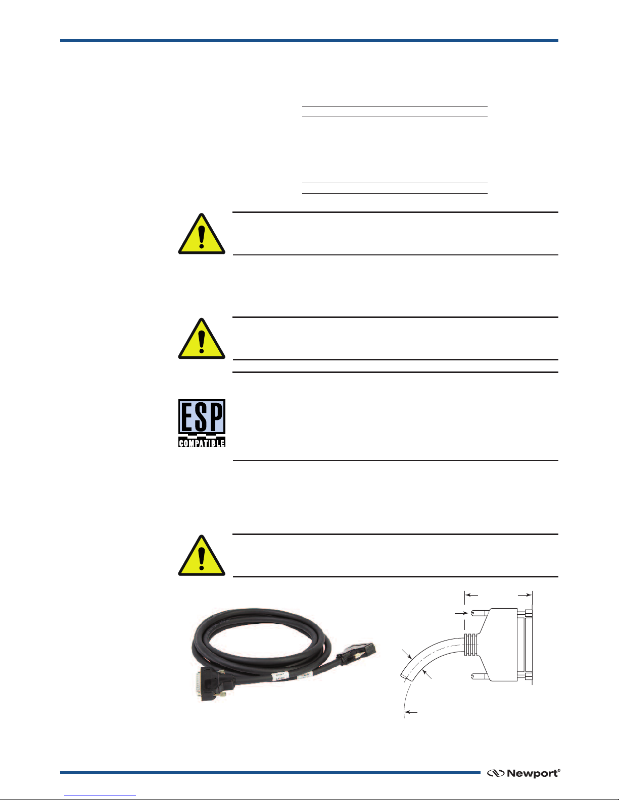
5.5 Cables
All IMS-V stages are delivered with MCAB-5 5-meter cables with a SUB-
D25M connector for direct connection to Newport Controllers.
WARNING
IMS-V Series translation stages operate only with a 5-meter max. cable.
Max. Payloa (N)
100 400
Max. Speed (mm/s) 20 5
Max. Payloa (N)
100
Max. Speed (mm/s) 20
CABLE
CONNECTOR STAGE
LOCKING
KNOBS
BENDING
STATIC CABLE: ≥1.50 (38)
CABLE IN MOTION: ≥3.78 (96)
2.28 (58)
DISCONNECTED
ø.39
(10)
SUB-D25 CONNECTOR SHOWN
DIMENSIONS IN INCHES (AND MILLIMETERS)

11 EDH0211En1051 — 12/18
IMS-V Series High-Performance Linear S ages for Ver ical Use
WARNING
This cable is shielded correctly. For a correct operation, make sure to
lock connectors (ground continuity provided by the cable).
WARNING
Keep this cable at a safe distance from other electrical cables in your
environment to avoid potential cross talk.
6.0 —Connection to Non-Newport Electronics
6.1 Connections
WARNING
Newport is not responsible for malfunction or damage of IMS-V stages
when used with non-Newport controllers.
WARNING
Newport guarantees “”compliance of IMS-V stages only if used with
Newport cables and controllers.
It is the customer’s responsibility to modify the cable and take care of
sensor signal connections, when using the stage with non-Newport
controllers.
End-of-Runs and Mechanical Zero are open collector type with a 5.6 V
protective Zener diode.
Iin max.: 16 mA
V max.: 5.25 V
NEWPORT
STAGE
5.6 V
EDH0211En1051 — 12/18 12
IMS-V Series High-Performance Linear S ages for Ver ical Use
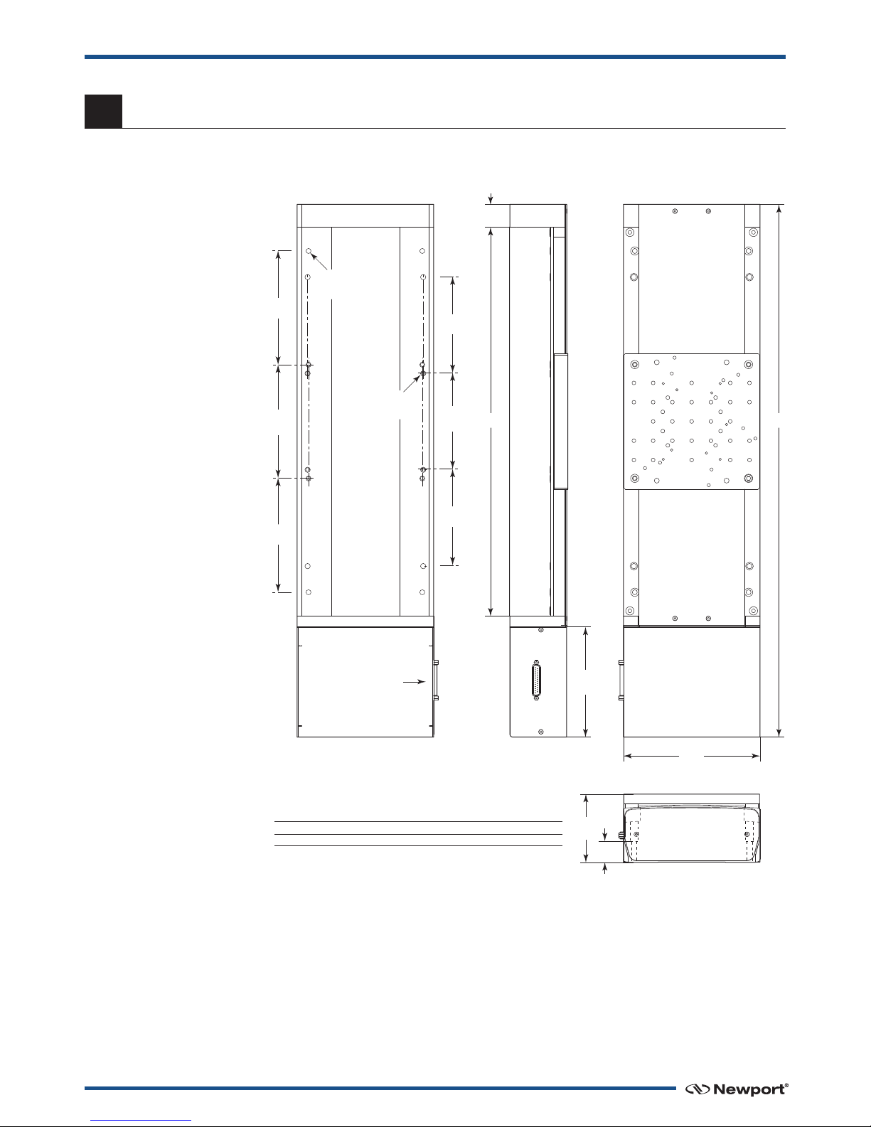
7.0 —Dimensions
7.1 (M-)IMS-V Stages
5.73
(145.5)
SUB-D25M
CONNECTOR
1.18
(30)
7.09
(180)
L1
L2
B
5
(127)
B
5.91
(150)
A
A
8HOLES CLR
FOR M6 SCREW
= =
8 HOLES CLR
FOR 1/4-20 SCREW
3.54
(90)
1.10
(28)
MODEL (METRIC) A B L 1L2TRAVEL
(M-)IMS100V 1.97 (50) 2.00 (50.8) 19.78 (502.5) 12.32 (313) 3.94 (100)
(M-)IMS300V 6.91 (150) 5.00 (127) 27.66 (702.5) 20.20 (513) 11.81 (300)
MODEL SHOWN: IMS300V
DIMENSIONS IN INCHES (AND MILLIMETERS)
This manual suits for next models
2
Table of contents


