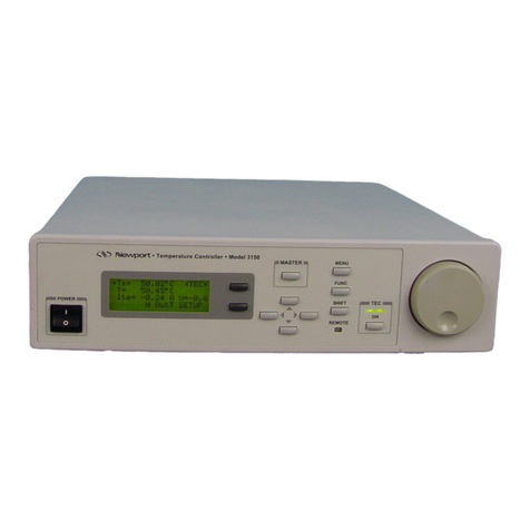
Newport 3040 User manual

Model 3040 Temperature Controller
User’s Manual

Newport Corporation, Irvine,
California, has been certified
compliant with ISO 9002 by the
British Standards Institution.
Corporate Headquarters Canada Italy Netherlands Taiwon R.O.C.
Newport Corporation Telephone: 905-567-0390 Telephone: 02-924-5518 Telephone: 030-6592111 Telephone: 2-2769-9796
1791 Deere Avenue Facsimile: 905-567-0392 Facsimile: 02-923-2448 Facsimile: 030-6570242 Facsimile: 2-2769-9638
Irvine, CA 92714 France Japan Switzerland United Kingdom
Telephone: 949-863-3144 Telephone: 1-60 91 68 68 Telephone: 03-5379-0261 Telephone: 01-740-2283 Telephone: 01635-521757
Facsimile: 949-253-1800 Facsimile: 1-60 91 68 69 Facsimile: 03-5379-0155 Facsimile: 01-740-2503 Facsimile: 01635-521348
Belgium Germany
Telephone: 016-402927 Telephone: 06151-36 21-0
Facsimile: 016-402227 Facsimile: 06151-36 21-52

Limited Warranty
Newport warrants that this product will be free from defects in materials and workmanship for a period of two
years from the date of shipment. If any such product proves defective during the applicable warranty period,
Newport, at its option, either will repair the defective product without charge for parts and labor or will provide a
replacement in exchange for the defective product.
In order to obtain service under this warranty, the customer must notify Newport of the defect before the
expiration of the warranty period and make suitable arrangements for the performance of service. In all cases the
customer will be responsible for packaging and shipping the defective product back to the service center specified
by Newport, with shipping charges prepaid. Newport shall pay for the return of the product to the customer if the
shipment is within the continental United States, otherwise the customer shall be responsible for all shipping
charges, insurance, duties and taxes, if the product is returned to any other location.
This warranty shall not apply to any defect, failure or damage caused by improper use or failure to observe proper
operating procedures per the product specification or operators manual or improper or inadequate maintenance
and care. Newport shall not be obligated to furnish service under this warranty 1) to repair damage resulting from
attempts by personnel other than Newport’s representatives to repair or service the product; 2) to repair damage
resulting from improper use or connection to incompatible equipment; 3) to repair damage resulting from
operation outside of the operating or environmental specifications of the product.
Products sold by Newport Corporation are not designed for use in life support equipment where malfunction of
such products can reasonably be expected to result in personal injury or death. Buyer uses or sells such products
for life support application at buyer’s own risk and agrees to defend, indemnify, and hold harmless Newport
Corporation from any and all damages, claims, suits, or expense resulting from such use.
NEWPORT’S LIABILITY FOR THE MERCHANTABILITY AND USE OF THE PRODUCT IS EXPRESSLY
LIMITED TO ITS WARRANTY SET OUT ABOVE. THIS DISCLAIMER AND LIMITED WARRANTY IS
EXPRESSLY IN LIEU OF ANY AND ALL REPRESENTATIONS AND WARRANTIES EXPRESS OR
IMPLIED, INCLUDING BUT NOT LIMITED TO, ANY IMPLIED WARRANTY OF MERCHANTABILITY
OR OF FITNESS FOR PARTICULAR PURPOSE, WHETHER ARISING FROM STATUTE, COMMON LAW,
CUSTOM OR OTHERWISE. THE REMEDY SET FORTH IN THIS DISCLAIMER AND LIMITED
WARRANTY SHALL BE THE EXCLUSIVE REMEDIES AVAILABLE TO ANY PERSON. NEWPORT
SHALL NOT BE LIABLE FOR ANY SPECIAL, DIRECT, INDIRECT, INCIDENTAL OR CONSEQUENTIAL
DAMAGES RESULTING FROM THE USE OF THIS PRODUCT OR CAUSED BY THE DEFECT, FAILURE
OR MALFUNCTION OF THIS PRODUCT, NOR ANY OTHER LOSSES OR INJURIES, WHETHER A
CLAIM FOR SUCH DAMAGES, LOSSES OR INJURIES IS BASED UPON WARRANTY, CONTRACT,
NEGLIGENCE, OR OTHERWISE. BY ACCEPTING DELIVERY OF THIS PRODUCT, THE PURCHASER
EXPRESSLY WAIVES ALL OTHER SUCH POSSIBLE WARRANTIES, LIABILITIES AND REMEDIES.
NEWPORT AND PURCHASER EXPRESSLY AGREE THAT THE SALE HEREUNDER IS FOR
COMMERCIAL OR INDUSTRIAL USE ONLY AND NOT FOR CONSUMER USES AS DEFINED BY THE
MAGNUSOM-MOSS WARRANTY ACT OR SIMILAR STATE CONSUMER WARRANTY STATUTE.
©1997, Newport Corporation
Irvine, California, USA
Part No. 24593-01
IN-08973
Rev. B
Printed 18-Sep-02

EC DECLARATION OF CONFORMITY
Model 3040 Temperature Controller
We declare that the accompanying product, identified with the “ ” mark, meets all
relevant requirements of Directive 89/336/EEC and Low Voltage Directive
73/23/EEC.
Compliance was demonstrated to the following specifications:
EN50081-1 EMISSIONS:
Radiated and conducted emissions per EN55011, Group 1, Class A
EN50082-1 IMMUNITY:
Electrostatic Discharge per IEC 1000-4-2, severity level 3
Rated Emission Immunity per IEC 1000-4-3, severity level 2
Fast Burst Transients per IEC 1000-4-4, severity level 3
Surge Immunity per IEC 1000-4-5, severity level 3
IEC SAFETY:
Safety requirements for electrical equipment specified in IEC 1010-1.
______________________ ______________________
Alain Danielo Jeff Cannon
VP European Operations General Manager-Precision Systems
Zone Industrielle 1791 Deere Avenue
4534 Beaune-la-Rolande, France Irvine, Ca. USA

i
Table of Contents
1. General Information ______________________________________________1
1.1 Introduction______________________________________________________ 1
1.2 Product Overview _________________________________________________ 1
1.3 Available Options and Accessories ___________________________________ 2
1.4 Safety Terms and Symbols__________________________________________ 2
1.4.1 Terms ______________________________________________________________ 2
1.4.2 Symbols ____________________________________________________________ 2
1.5 General Warnings and Cautions _____________________________________ 3
2. System Operation_________________________________________________5
2.1 Introduction______________________________________________________ 5
2.2 Installation_______________________________________________________ 5
2.2.1 AC Power Considerations ______________________________________________ 5
2.2.2 Tilt-Foot Adjustment __________________________________________________ 5
2.2.3 Rack Mounting_______________________________________________________ 6
2.2.4 Ventilation Requirements_______________________________________________ 6
2.2.5 Power-Up Sequence___________________________________________________ 6
2.2.6 Quick Start __________________________________________________________ 6
2.3 Introduction to the 3040 Front Panel _________________________________ 6
2.3.1 Model 3040 _________________________________________________________ 6
2.4 General Operation ________________________________________________ 7
2.4.1 Display Elements _____________________________________________________ 7
2.4.1.1 Static Fields _______________________________________________________ 8
2.4.1.2 Non-Editable Data Fields_____________________________________________ 8
2.4.1.3 Editable Data Fields_________________________________________________ 8
2.4.1.3.1 Changing Data Fields_____________________________________________ 8
2.4.1.4 Controls __________________________________________________________ 8
2.4.2 Main Screen _________________________________________________________ 9
2.4.3 Menu Structure_______________________________________________________ 9
2.4.3.1 TEC Setup Menu __________________________________________________ 10
2.4.3.2 Communications Menu _____________________________________________ 10
2.4.3.3 System Menu _____________________________________________________ 11
2.4.3.3.1 Calibration Menu _______________________________________________ 12
2.4.3.4 Save/Recall Menu _________________________________________________ 12
2.5 Rear Panel Familiarization ________________________________________ 13
2.5.1 RS-232 Connector ___________________________________________________ 13
2.5.2 GPIB Connector_____________________________________________________ 13
2.5.3 TEC Output Connector _______________________________________________ 13
2.5.4 Input Power Connector _______________________________________________ 14
2.5.5 GND Post__________________________________________________________ 14

ii
2.6 Warm Up and Environmental Consideration _________________________ 14
3. Temperature Controller Operation__________________________________15
3.1 Temperature Controller (TEC) _____________________________________ 15
3.2 TEC Safety Features ______________________________________________ 15
3.2.1 Conditions Which Will Automatically Shut Off the TEC Output ________________ 15
3.2.2 Lockout Dial Button __________________________________________________ 15
3.2.3 TEC Interlock _______________________________________________________ 15
3.3 The TEC Connector ______________________________________________ 16
3.3.1 TEC Grounding Consideration __________________________________________ 16
3.4 TEC Operation __________________________________________________ 16
3.4.1 TEC Main Screen ____________________________________________________ 16
3.4.2 TEC Setup Menu_____________________________________________________ 17
3.4.2.1 The
tand uSoft Keys ____________________________________________ 17
3.4.2.2 Sensor (Sens)______________________________________________________ 17
3.4.2.3 Mode ____________________________________________________________ 18
3.4.2.3.1 Constant Temperature Mode (Const T)_______________________________ 18
3.4.2.3.2 Constant Resistance/Reference Mode (Const R)________________________ 18
3.4.2.3.3 Constant Current Mode (Const ITE)_________________________________ 18
3.4.2.3.4 Effects of Calibration on TEC modes ________________________________ 18
3.4.2.4 Gain_____________________________________________________________ 19
3.4.2.5 Limits ___________________________________________________________ 19
3.4.2.5.1 TE Current Limit (Lim ITE) _______________________________________ 19
3.4.2.5.2 Temperature Limits (Lim Th and Lim Tl)_____________________________ 20
3.4.2.5.3 Resistance/Reference Limits (Lim Rh and Lim Rl)______________________ 20
3.4.2.6 Tolerances (Tol Time and Tol Temp)___________________________________ 20
3.4.2.7 C1, C2, C3, Ro ____________________________________________________ 20
3.4.3 Thermistor and Thermistor Current Selection_______________________________ 21
3.4.3.1 Introduction_______________________________________________________ 21
3.4.3.2 Thermistor Range __________________________________________________ 21
3.4.3.3 Temperature Resolution _____________________________________________ 22
3.4.3.4 Selecting Thermistor Current _________________________________________ 23
3.4.3.5 Selecting Thermistors _______________________________________________ 23
3.4.3.6 The Steinhart-Hart Equation __________________________________________ 24
3.4.3.7 Table of Constants__________________________________________________ 26
3.4.4 AD590 and LM335 ___________________________________________________ 26
3.4.4.1 General __________________________________________________________ 26
3.4.4.2 AD590 Sensor _____________________________________________________ 26
3.4.4.3 LM335 Sensor_____________________________________________________ 27
3.4.4.4 Determining C1 and C2 for the AD590 and LM335________________________ 28
3.4.4.4.1 One Point Calibration Method _____________________________________ 28
3.4.4.4.2 Two Point Calibration Method _____________________________________ 29
3.4.5 RTD Sensors ________________________________________________________ 30
3.4.5.1 RTD Constants ____________________________________________________ 30
4. Principles of Operation ___________________________________________31

iii
4.1 Introduction_____________________________________________________ 31
4.2 TEC Theory of Operation _________________________________________ 31
4.2.1 TEC Interface_______________________________________________________ 32
4.2.2 Limit DAC _________________________________________________________ 32
4.2.3 Set Point DAC ______________________________________________________ 32
4.2.4 A/D Converter ______________________________________________________ 33
4.2.5 Sensor Select _______________________________________________________ 33
4.2.6 Difference Amplifier _________________________________________________ 33
4.2.7 Proportional Amplifier and Integrator ____________________________________ 33
4.2.8 Bipolar Output Stage _________________________________________________ 33
4.2.8.1 Current Limiting___________________________________________________ 34
4.2.8.2 Current Limit Condition Sensing ______________________________________ 34
4.2.8.3 Voltage Controlled Current Source ____________________________________ 34
4.2.8.4 Voltage Limit Condition Sensing______________________________________ 34
4.2.9 TEC Control Modes__________________________________________________ 34
4.2.9.1 T Mode__________________________________________________________ 34
4.2.9.2 R Mode _________________________________________________________ 35
4.2.9.3 ITE Mode_________________________________________________________ 35
4.3 Microprocessor Board ____________________________________________ 36
4.3.1 Microprocessor _____________________________________________________ 36
4.3.2 Memory ___________________________________________________________ 37
4.3.3 Serial Interface ______________________________________________________ 37
4.3.4 Front Panel Interface _________________________________________________ 37
4.3.5 GPIB Interface ______________________________________________________ 37
4.3.6 RS-232 Serial Interface _______________________________________________ 37
4.4 Power Supplies __________________________________________________ 38
4.4.1 Power Supply_______________________________________________________ 38
4.4.2 Main Supply________________________________________________________ 38
5. Tips and Techniques _____________________________________________39
5.1 Introduction_____________________________________________________ 39
5.2 TEC Limits _____________________________________________________ 39
6. Maintenance ___________________________________________________41
6.1 Introduction_____________________________________________________ 41
6.2 Fuse Replacement ________________________________________________ 41
6.3 Cleaning ________________________________________________________ 41
7. Calibration_____________________________________________________43
7.1 Calibration Overview _____________________________________________ 43
7.1.1 Environmental Conditions _____________________________________________ 43
7.1.2 Warm-Up __________________________________________________________ 43

iv
7.2 TEC Calibration _________________________________________________ 43
7.2.1 Recommended Equipment______________________________________________ 43
7.2.2 Local Operation Thermistor Calibration ___________________________________ 44
7.2.3 Remote Operation Thermistor Calibration _________________________________ 44
7.2.4 Local Operation AD590 Sensor Calibration ________________________________ 45
7.2.5 Remote Operation AD590 Sensor Calibration ______________________________ 45
7.2.6 Local Operation LM335 Sensor Calibration ________________________________ 46
7.2.7 Remote Operation LM335 Sensor Calibration ______________________________ 46
7.2.8 Local Operation RTD Calibration________________________________________ 47
7.2.9 Remote Operation RTD Calibration ______________________________________ 47
7.2.10 RTD Lead Resistance Calibration (Offset Null) _____________________________ 48
7.2.11 Local Operation ITE Current Calibration __________________________________ 48
7.2.12 Remote Operation ITE Current Calibration ________________________________ 49
8. Factory Service _________________________________________________51
8.1 Introduction _____________________________________________________ 51
8.2 Obtaining Service ________________________________________________ 51
9. Error Messages _________________________________________________55
9.1 Introduction _____________________________________________________ 55
10. Specifications _________________________________________________57
10.1 Temperature Controller (TEC) Specifications_________________________ 57
10.2 General Specifications_____________________________________________ 58
Tables
Table 1 - TEC Connector Pintouts ___________________________________________________ 16
Table 2 - Comparison of Curve Fitting Equations _______________________________________ 25
Table 3 - Thermistor Constants _____________________________________________________ 26
Table 4 - RTD Constants___________________________________________________________ 30
Table 5 - Recommended Test Equipment ______________________________________________ 43
Table 6 - Error Codes_____________________________________________________________ 55
Figures
Figure 1 - Model 3040 Front Panel ___________________________________________________ 7
Figure 2 - Main Screen_____________________________________________________________ 9
Figure 3 - Model 3040 Menu Groups_________________________________________________ 10
Figure 4 - Communications Menu ___________________________________________________ 10
Figure 5 - System Configure Menu___________________________________________________ 11
Figure 6 - Calibration Menu________________________________________________________ 12
Figure 7 - Save/Recall Menu _______________________________________________________ 12
Figure 8 - Rear Panel _____________________________________________________________ 13
Figure 9 - TEC Main Screen________________________________________________________ 16
Figure 10 - TEC Setup Menu _______________________________________________________ 17

v
Figure 11 - Thermistor Temperature Range ___________________________________________ 22
Figure 12 - Thermistor Resistance versus Temperature __________________________________ 25
Figure 13 - AD590 Nonlinearity ____________________________________________________ 27
Figure 14 - 3040 Block Diagram____________________________________________________ 31
Figure 15 - TEC Board Diagram ___________________________________________________ 32
Figure 16 - Microprocessor Board Block Diagram _____________________________________ 36
Figure 17 - Power Supply Block Diagram ____________________________________________ 38


1
CHAPTER 1
1. General Information
1.1 Introduction
This chapter describes the features, options, accessories, and specifications of the
Model 3040.
1.2 Product Overview
PRODUCT FEATURES
qGPIB/IEEE 488.2 and RS-232C Interfaces
qTemperature Controller (TEC)
•Model 3040: 32 Watt (4A/8V), ultra stable bipolar output
•Thermistor, AD590, LM335, and Pt RTD sensors
High Power Temperature Controller Fulfills All Your Thermo
Electric (TE) Cooling Needs
The 32 Watt Temperature Controller is offered to meet your most demanding TE
cooling needs. It may be operated in one of three modes:
•Constant Temperature
•Constant Resistance
•Constant TE Current
Short term stability is better than 0.0005°C while long term stability is better than
0.001°C. Four sensor types are compatible with this TEC:
•Thermistors
•AD590 series
•LM335 series
•100ΩPlatinum RTDs
With the sensor’s calibration constants, the actual temperature is displayed in °C on
the front panel.
GPIB/IEEE-488.2 and RS232 Interfaces Gives Power to
Remotely Control and Collect Data.
For ultimate control a GPIB/IEEE-488.2 interface is available. All control and
measurement functions are accessible via the GPIB interface. In addition, standard
serial RS-232C ports allow simpler interfacing to a PC.

2 Chapter 1 General Information
1.3 Available Options and Accessories
Model 3040 Advanced Temperature Controller
3040 Temperature Controller (32 W)
Accessories
300-02 Temperature Controller Cable
300-04 Temperature Controller/Mount Cable
300-16 10.0 kΩthermistor (± 0.2°C)
300-22 AD592CN IC Sensor
35-RACK Rack Mount Kit
Newport Corporation also supplies temperature controlled mounts, lenses, and other
accessories. Please consult with your representative for additional information.
1.4 Safety Terms and Symbols
1.4.1 Terms
The following safety terms are used in this manual:
The WARNING heading in this manual explains dangers that could result in
personal injury or death.
The CAUTION heading in this manual explains hazards that could damage the
instrument.
In addition, a NOTE heading gives information to the user that may be beneficial in
the use of this instrument.
1.4.2 Symbols
The following symbols are used in this manual and on the instrument:
Power Off
Power On
!Refer to the documentation.
Earth Ground

Chapter 1 General Information 3
1.5 General Warnings and Cautions
The following general warning and cautions are applicable to this instrument:
WARNING
This instrument is intended for use by qualified
personnel who recognize shock hazards or laser hazards
and are familiar with safety precautions required to
avoid possible injury. Read the instruction manual
thoroughly before using, to become familiar with the
instrument’s operations and capabilities.
WARNING
The American National Standards Institute (ANSI) states
that a shock hazard exists when probes or sensors are
exposed to voltage levels greater then 42 VDC or 42V
peak AC. Do not exceed 42V between any portion of the
Model 3040 (or any attached detector or probe) and
earth ground or a shock hazard will result.
CAUTION
There are no serviceable parts inside the Model 3040.
Work performed by persons not authorized by Newport
Corporation may void the warranty. For instructions on
obtaining warranty repair or service please refer to
Chapter 8 of this manual.


5
CHAPTER 2
2. System Operation
2.1 Introduction
This chapter describes how to operate the 3040 temperature controller.
2.2 Installation
CAUTION
Although ESD protection is designed into the 3040,
operation in a static-fee work area is recommended.
2.2.1 AC Power Considerations
The 3040 can be configured to operate at a nominal line voltage of 100, 120, 220, or
240 VAC. Normally, this is done at the factory and need not be changed before
operating the instrument. However, be sure that the voltage setting is correct on the
power input and correct fuses are installed per chapter 6 before connecting to an AC
source. The 3040 is shipped set for 120 VAC and a caution sticker is placed on the
input power connector.
CAUTION
Do not exceed 250VAC on the line input.
Do not operate with a line voltage that is not within
±10% of the line setting. Too low of an input voltage
may cause excessive ripple on the DC supplies. Too
high of an input voltage will cause excessive heating.
WARNING
To avoid electrical shock hazard, connect the
instrument to properly earth-grounded, 3-prong
receptacles only. Failure to observe this precaution can
result in severe injury or death.
2.2.2 Tilt-Foot Adjustment
The 3040 has front legs that extend to make it easier to view the LCD display. To use
them, place the 3040 on a stable base and rotate the legs downward until they lock
into position.

6 Chapter 2 System Operation
2.2.3 Rack Mounting
The 3040 may be rack mounted by using a 3040 rack mount kit. All rack mount
accessory kits contain detailed mounting instructions.
2.2.4 Ventilation Requirements
Rear panel area needs 2 to 4 inches of clearance for air circulation.
2.2.5 Power-Up Sequence
Setup input power connector switch to desired voltage, then connect 3040 to AC
power source. With the 3040 connected to an AC power source, set the power switch
to “I” to supply power to the instrument and start the power-up sequence.
During the power-up sequence, the following takes place. For about 5 seconds an
initialization screen is displayed. The software version is displayed in the lower left
corner of the screen. During this time a self-test is performed to ensure that the 3040
hardware and software are communicating. If the 3040 cannot successfully complete
this test, an error message will be displayed.
After this test, the 3040 is configured to the state it was in when the power was last
shut off and displays the Main screen.
2.2.6 Quick Start
After the power-on sequence is complete, the 3040 goes to the Main screen. To set
up the TEC, press the MENU button, then select TEC Setup Menu. The up and down
cursor keys will allow the selection of all the TEC parameters, using the cursor keys
and the dial set the parameter values. When finished, return the TEC to the Main
screen by pressing the MENU button.
Enter the desired set point value using the cursor keys or the dial. Press the TEC On
key to operate the TEC. The LED illuminates to indicate TEC operation. To turn the
TEC off, press the TEC On key again.
2.3 Introduction to the 3040 Front Panel
2.3.1 Model 3040
Described below are the functions of each area of the Model 3040 front panel, as
shown in Figure 1.

Chapter 2 System Operation 7
Figure 1 - Model 3040 Front Panel
1. Power On/Off Switch - Switches on/off the AC power to the unit.
2. Error LED - Indicates that an error has occurred. Instrument will also display
the error message on the LCD display. See chapter 9 for additional information
on errors.
3. Remote LED - Indicator will light to show when the unit is being computer
controlled. See section 2.4.1 for additional information on remote mode.
4. TEC On LED - Indicates TEC output is on.
5. TEC On Button - Turns the TEC output on/off.
6. Cursor Control Keys - Moves cursor up or down between editable data fields.
The left arrow decrements values in numerical entry fields, or as a previous
choice in a multi-choice entry field. The right arrow increments values in
numerical entry fields, or as a next choice in multi-choice entry fields. See
section 2.4.1.3 for a description of data fields.
7. MENU Key - Switches to the main menu from any screen in the system (see
section 2.4.3).
8. Lockout Dial Key - Used to enable/disable use of the dial.
9. Lockout Indicator LED - Indicates Dial is locked out.
10. Dial - Used to continuously vary certain parameters. The dial has an acceleration
factor that causes the rate of change to increase as the dial is turned faster.
Turning slowly allows for a fine adjustment at the smallest displayed decimal
place.
2.4 General Operation
2.4.1 Display Elements
The Model 3040 uses a character display to depict information about the current state
of the system. The display can be broken down into four basic elements: static fields,
non-editable data fields, editable data fields, and soft key labels.

8 Chapter 2 System Operation
2.4.1.1 Static Fields
Static fields are elements on the display which do not change from moment to
moment. These can include screen titles and error messages.
2.4.1.2 Non-Editable Data Fields
Non-editable data fields are used mainly to display read back information, such as
temperature. These fields can have a prefix or suffix label, such as “Ts=” or “A”, and
are periodically updated by the system.
2.4.1.3 Editable Data Fields
Editable data fields are used for TEC and system settings such as current set point,
temperature set point, display contrast, etc. An editable field has three distinct display
states: focused, non-focused, and read-only.
The focused state indicates that the field has the input “focus.” When a field has the
focus, a right pointing arrow (→) is placed to the left of the field. Any keyboard entry
or dial adjustment will be applied to the field, and only one field at a time on the
display can have focus. Move between fields using the up and down arrow keys.
The non-focused state indicates that the field is editable, but does not currently have
the focus. These fields are indicated with a right pointing triangle (8) to the left of
the field. Using the up and down arrows, focus can be moved to these fields.
When the editable data field is in the read-only state, it looks and acts exactly like a
non-editable data field. Like the non-editable data field, it cannot have focus, and the
up or down arrow keys will skip over the field. This state is used primarily to lockout
specific data elements from front panel change when the Model 3040 is in remote
mode. Any RS-232 communication will place the unit in remote mode, and editable
fields that are protected during remote operations change to the read only state.
2.4.1.3.1 Changing Data Fields
A data field can only be changed from the front panel when the field is the focus.
Some fields are numeric-based, such as current set point or temperature limits. Other
fields are multi-choice fields, such as Yes/No fields. Both types are changed with the
left and right arrows or the dial.
2.4.1.4 Controls
There are certain functions in the 3040, such as saving and recalling bins, that require
a “button push”. Because the 3040 has no additional buttons to do this function, it
uses a “soft button”. A soft button is similar to an edit field, but instead of selecting a
value with the left and right arrow keys when the field is selected, the left and right
arrow keys function as custom defined buttons for as long as that field is selected.

Chapter 2 System Operation 9
For example, the return to local function is not a setting or value, but a state of
operation. A soft button for return to local might look like this:
→Local →Set
When this field is selected, as in this example, pressing the right arrow key would set
the unit to local mode. There are also elements on the 3040 which us the left arrow as
well, such as this example:
→Save ←Bin →Recall
In this case, pressing the left arrow key will save the bin information, while pressing
the right arrow key would recall the bin information.
2.4.2 Main Screen
The system main screen is shown below, and is discussed in detail in section 3.4.1
and later. The screen is displayed after power on initialization, and its displayed
elements will depend on the mode of operation. In this example, the unit is in
constant temperature mode, displaying the temperature set point, current read back,
and temperature read back.
→Ts= 25.00 °C OutT
T= 23.95 I= 0.00
Figure 2 - Main Screen
2.4.3 Menu Structure
The 3040 has a simple menu structure for changing the operation settings, such as
limits, communications parameters, and so forth. Each menu group has settings
accessible by first pressing the MENU button, then using the cursor keys to navigate
through the menus. When discussing the menu items within a menu, all the items are
shown in a single box.
NOTE
The 3040 display is a two line display, therefore only
two elements will be visible at a time.

10 Chapter 2 System Operation
TEC
Setup
Communications System Save/
Recall
\/
Calibration
Figure 3 - Model 3040 Menu Groups
2.4.3.1 TEC Setup Menu
The TEC Setup Menu is covered in section 3.4.2, and covers settings that pertain to
the operation of the TEC.
2.4.3.2 Communications Menu
Communications t
→Local →Set
4Err While Rmt= No
4GPIB Address= 4
4Speed= 9600 Baud
4Terminal Mode= No
Figure 4 - Communications Menu
The Communications menu contains the setup parameters for GPIB and RS-232C
communications.
The Local soft button will return the 3040 to local mode after being controlled over
GPIB or RS-232C.
Error messages may appear on the display when error conditions occur which force
the output off or reflect hardware errors in the 3040. Display of error messages on the
3040 screen may be disabled while in remote mode by setting Err While Rmt to No.
Errors will continue to accumulate in the error queue, but will not be displayed on-
screen.
GPIB Address selects the device address on the GPIB bus. The allowed range is 1 to
31.
Speed controls the speed of the RS-232C interface. The allowed speeds are 300,
1200, 2400, 4800, 9600, 19200, and 38400. The parity is NONE, and data bits are 8.
Table of contents
Other Newport Temperature Controllers manuals
