Newwave PUREWATER PW 100-M5 Series User manual


Warning!
Hazardous Voltage: Can Shock, Burn or Cause Death.
6Disconnect power at main panel before connecting electrical power
supply to reclaim unit panel or working on electrical connections.
6Ground reclaim unit before connecting to the electrical power
supply. Failure to ground reclaim unit can cause severe or fatal
electrical shock hazard.
6Wire reclaim unit for correct voltage. See “Controls and Electrical”
section of this manual and “Installation & Operating Instructions”
label on the electrical panel cover.
6Meet National Electrical Code and local codes for wiring.
6Follow wiring instructions in this manual when connecting the
reclaim unit to the power supply.
Caution! This Reclaim Unit has been evaluated for use
with water only.
For Assistance, Contact PurWater 800-882-8854

Table of Contents
Reclaim Water Systems
6Reclaim General Description ...............................................................5
6PurWater Reclaim System Description ……………………………..…5-9
System Installation
6Frame ...............................................................................................10
6Reclaim Unit Piping …………………………………………………..10-14
6Reclaim Tanks ……………………………………………….………..14-17
6Electrical Safety ................................................................................18
6Controls and Electrical Wiring …………………………………….…19-21
System Start-Up, Operation and Maintenance
6Electrical Component / Control Functions …………………………22-25
6Start-Up ………………………………………………………………..26-29
6Operation ………………………………………………………………30-34
6Maintenance Schedule for Air Sparger Systems ………………….35-42
6Maintenance Schedule for Ozone Systems ……………………….43-55
Troubleshooting Guide ………………………………………….57-59
Warranty ....................................................................................... 60
Returned Goods Authorization Policy ...................................... 61
Start Up Warranty Validation ...................................................... 62
Appendix
a. Ozone Material Safety Data Sheet (MSDS)
b. Sta-Rite Self-Priming Centrifugal Pumps – “D” Series

Reclaim Water Systems
General Description:
The use of reclaim water has become an important method for the car wash
operator to reduce his / her operating expenses (water / sewer costs) and start-up
costs (impact / connection fees). Many municipalities are requiring the use of
reclaim water in car wash operations and operators are continually looking for
ways to increase profits, so reclaim systems are becoming essential in the overall
operation of the wash.
Reclaim water is the re-use of water that has already been used in the wash and
recovered by the drain system in the wash bay. Most drain systems consist of a
catch basin to settle out the large solids, followed by two or three underground
reclaim tanks to remove oil & grease, floatable materials and settleable solids.
Overflow water from the last reclaim tank is then discharged to sewer or an oil /
water separator.
Water from the reclaim tanks contains solids that have not settled within the tank.
These solids are typically small in size (less than 150 microns) and consist of sand,
clay, and silt. These solids can increase wear on pumps, piping, and nozzles, and
increase the potential of plugging nozzles. Reclaim water also is a great
environment for growing bacteria which can create plugging and odor problems.
Typically, anaerobic bacteria (bacteria that grow in the absence of oxygen) will
grow beneath the settled solids in the reclaim tank. This type of bacteria produces
hydrogen sulfide and methane that has an odor similar to rotten eggs. A properly
designed reclaim system must both remove solids and provide biological / odor
control.
A PurWater reclaim system takes water from the last compartment of the reclaim
tank and treats it further so that the quality is acceptable for re-use in the wash.
The PurWater reclaim system also returns a portion of the water back to the
reclaim tank to provide biological / odor control. Reclaim water that is treated by a
PurWater system can then be used for the undercarriage, side panel blasters,
mitters, and high pressure rinse cycles which greatly reduces the overall amount of
city water required by the wash and the amount of water discharged to sewer.
Typically, 60-85% of the water used on the car can be reclaim water.
PurWater Reclaim System:
The PurWater Reclaim System consists of cyclone separators to remove solids
down to the 5 micron range and one of three methods (air sparger, enzyme
addition or ozone addition) to control odor and biological growth. The system is
contained on a compact frame with its own pump / motor and controls. The system
will recirculate water continuously back to the second compartment of the reclaim
tank for odor and biological control. When a demand for reclaim water is received
from the wash, the system will provide treated reclaim water.

PWFS (Flood) Series Systems: The PWFS (Flood) series systems consist of a
cyclonic sand separator, pump / motor, controls, and an air sparger designed to
treat 60 or 100 gpm of reclaim water. The sand separator will remove down to 70
micron solid particles and is adequate for use in Auto Dealer or Fleet / Flooder
Arch Friction wash applications. When the wash demands water, the system
provides treated water to the wash and recirculates water through the air sparger,
located in the reclaim tank, for odor and biological control. If the wash does not
demand water for 10 minutes, the system will automatically recirculate treated
water back to the reclaim tank through the air sparger for five minutes. This
operation ensures that odor and biological control are performed periodically to
prevent the reclaim tank from going septic. Drawing #1G shows the Process &
Instrumentation Diagram (P&ID) for the PWFS (Flood) series design.
PW 100/200/300-M5 Series Systems: The PW 100/200/300-5M series systems
consist of high efficiency cyclones, pump / motor, controls and one of three odor
control systems … air sparger, enzyme addition, or ozone addition. The standard
systems are designed to treat 30, 60, and 90 gpm of reclaim water. The new
generation of high efficiency cyclones will remove down to 5 micron solids, so that
the treated water can be used by high pressure touchless or friction in-bay
automatics and tunnel wash applications. The system utilizes a Variable Frequency
Drive (VFD) on the pump motor which is controlled by the wash demand, to vary
the amount of water that is treated and delivered. Water continuously recirculates
back to the reclaim tank, both when water is demanded by the wash and when
there is no demand. Up to three different demand inputs from the wash can be
incorporated into the VFD. The PW 100/200/300-5M system piping also
incorporates a city water intake line for use as: 1) a by-pass to meet wash water
demands in case the system is not operating due to an extremely low level in the
reclaim tank or a fault; and 2) an automatic pump prime operation for system start-
up.
Air Sparger
Biological and odor control are accomplished by using one of three methods,
depending upon the model number supplied. The first method uses an air sparger
(models ending in 5MAS), which is mounted within the reclaim tank above the
water level. The air sparger will bring in air as water is passed through the sparger.
The aerated water will add oxygen to the tank water which will control the
anaerobic bacteria growth. Drawing #2G shows the Process & Instrumentation
Diagram (P&ID) for the Air Sparger Design.
Biological
A second method of control is to add periodically an enzyme that consumes the
organic material in the reclaim water that is used as a food source by the bacteria
(models ending in 5MB). With no food source, the bacteria cannot survive and
multiply. The enzyme is fed into the recirculation water using a small feed pump
that draws from a feed tank. The feed tank is periodically filled with concentrated
enzyme and city water. The recirculation water with enzyme goes through an air
sparger in the reclaim tank to provide aeration and better biological / odor control.
Drawing #3G shows the Process & Instrumentation Diagram (P&ID) for the
Biological Design.

Ozone
The third method utilizes ozone to kill the bacteria (models ending in 5M12O or
5M24O). Ozone is a contact killing agent, similar to chlorine used in city water.
Ozone (O3) is generated by concentrating the oxygen (O2) in ambient air and
passing the concentrated oxygen through a high voltage electric current to produce
ozone. The ozone laden gas is then educted into the recirculation water stream
and into the reclaim tank to kill the bacteria. Drawing #4G shows the Process &
Instrumentation Diagram (P&ID) for the Ozone Design.
Caution: Breathing concentrated ozone can create severe breathing problems.
Precautions must be made to prevent exposure to concentrated ozone.
PWFS – 5MAS (Flood Series)
Left: PW200-5MAS Center: PW300-5M240
Right: PW400-5MAS

Drawing #1G
Drawing #2G

PG
To Car
Wash
S
Recirculation
Water
Cyclone
Reclaim
Water
PurWater Reclaim Water System
Biological (Enzyme) Design
Underflow
(Solids)
Overflow
(Treated Water)
Reclaim
Water Feed
Pump / Motor S
Pump Prime
S
City Water ByPass
City
Water
In
LS
M
S
Solenoid
Valve
By Customer
Flapper
Foot
Valve
PG
Orifice
Sparger
Pressure
Gauge
Solenoid
Valve
(N.C.)
Check
Valve
Solenoid
Valve
(N.C.)
Cyclone
Motorized
Ball Valve
Pressure
Gauge
Check
Valve
Basket
Strainer
Level
Switch
Process & Instrumentation Diagram (P&ID)
Low
Low
S
Solenoid
Valve
(N.O.)
PS
Pressure
Switch
PT
Pressure
Transmitter
Catch Basin
TANK #3
From Car
Wash
Overflow
To Sewer
TANK #2 TANK #1
M
Enzyme Feed
Tank Enzyme Feed
Pump / Motor
Check
Valve
Drawing #3G
Drawing #4G

System Installation
PurWater systems are designed for easy installation. However, if you should have
any questions, please contact us at (916) 978-9990 or (800) 882-8854 in
Sacramento, CA. Office hours are 7AM to 5 PM, Pacific Standard Time, Mon-Fri.
I. PW 100/200/300-5M Series Reclaim Systems, including:
a) Model PW100-5MAS (3HP, 30 GPM, Air Sparger)
b) Model PW100-5MB (3HP, 30 GPM, Enzyme Feed System and Air
Sparger)
c) Model PW100-5M12O (3HP, 30 GPM, 12 Gram Ozone)
d) Model PW200-5MAS (5HP, 60 GPM, Air Sparger)
e) Model PW200-5MB (5HP, 60 GPM, Enzyme Feed System and Air
Sparger)
f) Model PW200-5M12O (5HP , 60 GPM, 12 Gram Ozone)
g) Model PW200-5M24O (5HP , 60 GPM, 24 Gram Ozone)
h) Model PW300-5MAS (5HP, 90 GPM, Air Sparger)
i) Model PW300-5MB (5HP, 90 GPM, Enzyme Feed System and Air
Sparger)
j) Model PW300-5M12O (5HP , 90 GPM, 12 Gram Ozone)
k) Model PW300-5M24O (5HP , 90 GPM, 24 Gram Ozone)
Frame:
The system is to be installed in a dry / clean / temperature controlled / covered
area. It is not designed to be in the wash bay or outdoors. The frame requires a
floor space of 48” wide by 16” deep, with a height of 75” (86” for ozone units). We
recommend a minimum clearance of 18” along the sides, front and top of all frames
to allow for routine maintenance and inspection. The floor frame should be placed
with its back along a wall and should be secured to the wall to prevent movement
of the frame. Some models may also have a wall mount frame for the ozone
generation system. This wall mount frame needs to set in close proximity of the
floor frame to allow both electrical and piping connections. The area should be free
of excessive moisture which can cause extreme corrosion or electrical failure.
Piping:
Fittings on these systems have some threaded connections which can come loose
during shipment. There are two unions used on the motorized ball valve on the inlet
piping, on the cyclone overflow piping, on the check valve on the recirculation line,
and on the Mazzei eductor (on ozone units only) on the recirculation line. There is
also a union on the cyclone underflow. Re-tighten these union connections and any
other threaded connections prior to introducing water into the system. We
recommend using Schedule 80 PVC for all connections to the reclaim unit. Rubber
hose is acceptable on all lines except the Suction Line (needs reinforced suction
hose) and the Recirculation Line on ozone systems (rubber is not compatible with
ozone).
1) Treated Water Line: This line has a pressure gauge (and a pressure
transducer on some units) and is to be connected to the wash. Solenoid
valves (supplied by others) need to be installed and controlled by the
wash controller when water is demanded by the wash. Do not reduce the
line size until reaching the wash equipment to prevent flow restriction
and pressure reduction. If connecting to a high pressure pump, we
recommend piping directly into the pump and not into the pump suction
tank. (See Drawing #1S.)
2) City Water Line: This line has a check valve that leads to two brass
solenoid valves on the reclaim unit. City water is to be connected, which will
then provide fresh water for a by-pass function to the wash and an
automatic pump prime operation. The city water supply line needs to be 1”
for the PW 100 series and 2” for the larger units to ensure enough pressure
and flow are available. Do not exceed a pressure of 100 psig on the city
water inlet.
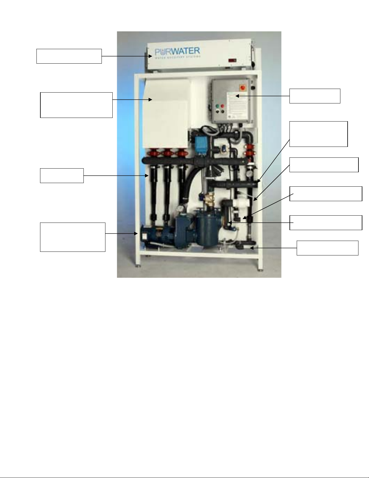
Ozone Generator
Oxygen
Concentrator
Cyclones
Pump / Motor
and Basket
Straine
r
Control Box
Treated Water
Line
City Water Line
Recirculation Line
Pump Suction Line
Underflow Line

S
M
City
Water
Inlet
Fresh Water
Storage Tank
Mechanical Float /
Valve
High Pressure
Pump
Water to
Wash
Check
Valve
Solenoid
Valve
Treated Reclaim
Water from Pur-
Water Unit
Plumbing Direct from Pur-Water
Reclaim Unit to High Pressure Pump
Notes:
1. Solenoid Valve to Open when High Pressure Pump Starts. Same Signal to be Used for Reclaim Activation.
2. Solenoid Valve Needed to Prevent Reclaim Unit from Pushing Water thru High Pressure Pump.
3. Solenoid Valve to be Mounted 4 Ft. Minimum from Pump Suction.
4. Check Valve to be Flapper Check Type. Do not Use Spring Check.
5. City Water Line and Mechanical Float / Valve Must be Sized to Ensure Enough Water Volume is Available to High Pressure Pump.
6. Suction Piping, Solenoid Valve, and Check Valve Must be Sized to Ensure Enough Water Volume is Available to High Pressure Pump.
Plumbing Reclaim Water Direct to the High Pressure Pump Prevents
Reclaim Water from Setting Stagnant in the Suction Storage Tank.
Biological Activity Will Accelerate in Stagnant Reclaim Water, Causing
Growth in the Tank and Odor in the Area.
Operation:
A) No Wash Demand / Reclaim Unit in Recirculation Mode: High Pressure
Pump is Off and Solenoid Valve is Closed. Line Pressure Keeps Check
Valve Closed.
B) Wash Demands Reclaim Water / Reclaim Unit On: High Pressure Pump
Operates and Solenoid Valve Opens. Reclaim Unit Ramps Up to Meet
Water Demand. As Long as Water Demand to High Pressure Pump is Met,
Check Valve Remains Closed.
C) Wash Demands Reclaim Water / Reclaim Unit Off: High Pressure Pump
Operates and Solenoid Valve Opens. No Reclaim Water from Reclaim
Unit, So Check Valve Opens to Feed Fresh Water from Storage Tank.
Drawing # 1S
3) Recirculation Line: This 1” line provides a return line of treated water back
into the first reclaim tank, compartment #2. A solenoid valve (normally open)
on this line closes only during the Automatic Pump Prime operation.
a. Air Sparger Units (Models ending in -5MAS): The recirculation line is
connected to the air sparger within the reclaim tank. (See below for air
sparger assembly installation.)
b. Enzyme Units (Models ending in -5MB): The recirculation line will be
supplied with an enzyme injection point on the reclaim unit and is connected
to the air sparger within the reclaim tank. (See below for air sparger
assembly installation.)
c. Ozone Units (Models ending in -5M12O or -5M24O): The recirculation line
will be supplied with a Mazzei eductor connected to an ozone generation
system. The line in the tank should extend halfway down the normal water
level and terminate in a tee to split the flow. An air sparger is not required.
(Note: Rubber hose is not compatible with ozone. All piping containing
ozone should be PVC.)
d. Air Sparger Assembly: The air sparger assembly is installed into the first
reclaim tank, compartment #2. It should be located so that it is accessible
from the manway as occasional inspection and maintenance are required.

Ensure the wall mount bracket is placed to allow the assembly to be
removed easily. The assembly consists of the air sparger, mounting
brackets, and inlet piping with a union. The bottom of the sparger nozzle
should be set 6-12” above the water level and pointed downward. If this is
not possible, mount the sparger horizontally so that it sprays against a side
wall. The top opening on the sparger body should have clearance to allow
air flow into the sparger. The union on the inlet allows the assembly to be
easily pulled out of the tank for maintenance and inspection.
Air Sparger Assembly
4) Pump Suction Line: Connect the suction line from the last compartment of the
last reclaim tank into the basket strainer inlet on the reclaim unit. Keep the size
of the line 2” for the PW 100 / 200 units and 3” for larger units. If hose is used,
ensure it is reinforced suction hose. Piping between the tank and reclaim system
should have a minimal amount of bends, threaded connections, and should
never go higher than the basket strainer inlet. The inlet pipe within the tank
should have a flapper type foot valve with a quick disconnect for maintenance,
and the bottom of the valve should be a minimum of 16 inches above the bottom
of the tank floor. We do not recommend the use of spring loaded check valves or
screens on the suction line. Pressure testing of both suction lines is
recommended before connecting to the reclaim unit.
5) Cyclone Underflow: The 1” line from the bottom of the cyclones should be
connected to the catch basin or the first reclaim tank compartment. An
underflow orifice assembly is installed on this line between two unions. Solids
captured from the cyclones are continuously removed when the system is
operating. The underflow line should be level or sloping downward to prevent
solids build-up in the piping or cyclones.
Air Sparger
Sparger Nozzle
Sparger Water Inlet
Air Intake Opening
(On Top)
Wall Mount Bracket

Underflow Orifice Assembly
Some units will have a few components that will mount off of the main reclaim unit
frame:
a) Enzyme Systems: For models ending in -5MB, the enzyme feed tank will set
on the floor close to the reclaim unit and must be connected to the enzyme feed
pump mounted on the reclaim unit frame. The feed tank is supplied with a
spigot and tubing which connects directly to the inlet of the feed pump. Tubing
and a plumbing kit with instructions is shipped with the system.
b) Wall Mount Ozone Systems: For certain models ending in -5M12O and -
5M24O, the oxygen concentrator and the ozone generator are installed on a
wall mount panel. If possible, locate the wall mount panel close to the reclaim
unit frame and on the right hand side (when facing the front). The Teflon tubing
supplied between the ozone generator and the Mazzei eductor on the
recirculation line must be connected. Ensure that the tubing has a minimal
amount of bends (not pinched) and is sealed tightly on the fittings.
II. Reclaim Tanks:
PurWater does not supply the underground reclaim tanks. These are typically pre-
cast concrete vaults that are sourced locally. However, we do recommend that the
tanks follow the following design parameters to ensure a successful operation.
Location Considerations for Reclaim Tanks:
1) Locate the Reclaim Tanks close to the Equipment Room to minimize the
length of suction pipe run to the Reclaim Unit.
2) Locate the Reclaim Tanks so that bends & elbows are minimized on the
suction piping.
3) Keep the piping below the reclaim pump inlet.
4) For ozone units, the Reclaim Tanks should be located outside the Wash Bay
and Equipment Room in an area that is well ventilated.
The following drawings show the recommended internal lay-out for the reclaim
tanks:

1) The Catch Basin is typically located in the bay and
is part of the trench used to collect water from the
wash that goes to the Reclaim Tanks.
2) The Catch Basin will collect heavy, large solids
(rocks) and floating materials (plastic bags &
bottles), keeping these items out of the Reclaim
Tanks.
3) The outlet of the Catch Basin must have an elbow
below the water level that will prevent floating
trash from entering the Reclaim Tanks. This elbow
also prevents ozone gas in the Reclaim Tanks from
moving up the inlet pipe and into the bay.
4) The separated solids (underflow) line from the
PurWater Reclaim Unit should be piped into the
Catch Basin. The drain line between the PurWater
Reclaim Unit and the Catch Basin should have a
minimal number of elbows to prevent plugging and
be large enough (2” to 3”) to allow for cleaning.

Reclaim Tank Plumbing – Suction Lines:
1) Two suction lines are recommended. One is used and one is a spare.
2) The minimum suction line size for a PW100 & 200 series is 2”. Larger units
require a 3” suction line.
3) Unions can be used above the water level to allow removal of the suction
line from the manway without draining the tank. Unions must be tight to
prevent suction leaks.
Reclaim Tank Plumbing – Foot Valves:
1) PurWater will supply two PVC Flapper Check Valves to attach to the suction
lines. We do not recommend the use of spring loaded check valves.
2) PurWater does not recommend using screens as part of or around the check
valves.
3) The bottom of the check valve should be a minimum of 16 inches above the
tank floor.
Reclaim Tank Plumbing – Low-Low Level Switch:
1) PurWater will supply one two-wire (yellow float) level switch.
2) The low-low level switch should be wired into a water-tight junction box
within the Reclaim Tank and wired through the 1” conduit to the PurWater
Reclaim Unit.

3) The switch should be installed a minimum of 9” above the bottom of the
check valve when the float is in the down position.
Reclaim Tank Plumbing – Sewer Overflow:
1) The sewer (overflow) connection is above the normal liquid level and should
only overflow when washing cars.
2) The sewer connection should slope downward to the main sewer line.
3) There must be a backflow preventer installed between the Reclaim Tanks
and the main sewer line.
Reclaim Tank Plumbing – Interconnecting Piping:
1) The piping between the tanks will set the liquid level in each tank. The
elevation and downward elbow help prevent floating material and settled
solids from moving to the next tank.
2) The piping between compartments within each tank helps prevent floating
material and settled solids from moving to the next compartment.
3) For the PW100 / 200 / 300 series, the interconnecting piping needs to be a
minimum of 4”. For larger units, the piping is a minimum of 6”.
Reclaim Tank Plumbing – Recirculation Lines:
1) The 1” Recirculation Line continuously flows from the PurWater Reclaim Unit to
provide odor control. The line should go into the second compartment of the first
tank.
2) For ozone systems, the line terminates halfway below the liquid surface in a tee.
3) For sparger systems, the line terminates above the liquid level and is connected
to the air sparger.
Reclaim Tank Plumbing – Miscellaneous Items:
1) Piping and conduit materials should be PVC. PurWater recommends using
Schedule 80 pipe as it is stronger than Schedule 40.
2) All piping to / from the PurWater Reclaim Unit should be accessible from a
manway. Occasional checks and maintenance are required.
3) All floor drains emptying into the Reclaim Tanks should be piped to go below
the water level within the tanks. This prevents any gas from backing up
through the line into the bay or equipment room. This is especially important
on ozone systems.
4) The following should not be piped into the reclaim system: a) Domestic
sewer lines (sinks / toilets); b) Backwash from carbon tanks; c) Regeneration
from softeners; d) Blowdown from compressors or boilers; e) Drains from
Service / Detail Bays; and f) Areas where tire shine is applied.
5) If Self Serve Bays are to be piped into the Reclaim Tanks, a separate
Reclaim Tank should be used. Contact PurWater for details.

Safety
Warning!
Hazardous Voltage: Can shock, burn, or cause death.
6Disconnect power at the main panel before connecting the electrical
power supply to the reclaim unit panel or working on electrical
connections.
6Ground the reclaim unit before connecting to the electrical power supply.
Failure to ground the reclaim unit can cause a severe or fatal electrical
shock hazard.
Step 1: Install, ground, wire and maintain the reclaim unit in accordance
with local electrical codes and ordinances that apply. Consult with local
building inspector for local code information.
Step 2: Ground the reclaim unit permanently using a wire of size and type
specified by local or National Electrical Code.
Do not ground to a gas supply line!
Step 3: Connect ground wire first. Connect to ground first, then to green
grounding terminal provided. Do not connect the reclaim unit power supply
until the unit is permanently grounded; otherwise serious or fatal electrical
shock hazard may be caused.
6Do not connect the 3-Phase reclaim power leads to a 1-Phase power
supply. Do not connect the 1-Phase reclaim power leads to a 3-Phase
power supply.
6The supply voltage must be within ±10% of the designated reclaim unit
voltage as shown on “Installation & Operating Instructions” label on
the electrical panel cover. Incorrect voltage can cause fire or seriously
damage reclaim unit and voids warranty. If in doubt consult a licensed
electrician.
Caution! This Reclaim Unit has been evaluated for use
with water only.
This manual suits for next models
14
Table of contents


