2FORM NO. L-20113-E-0501
THEORY OF OPERATION
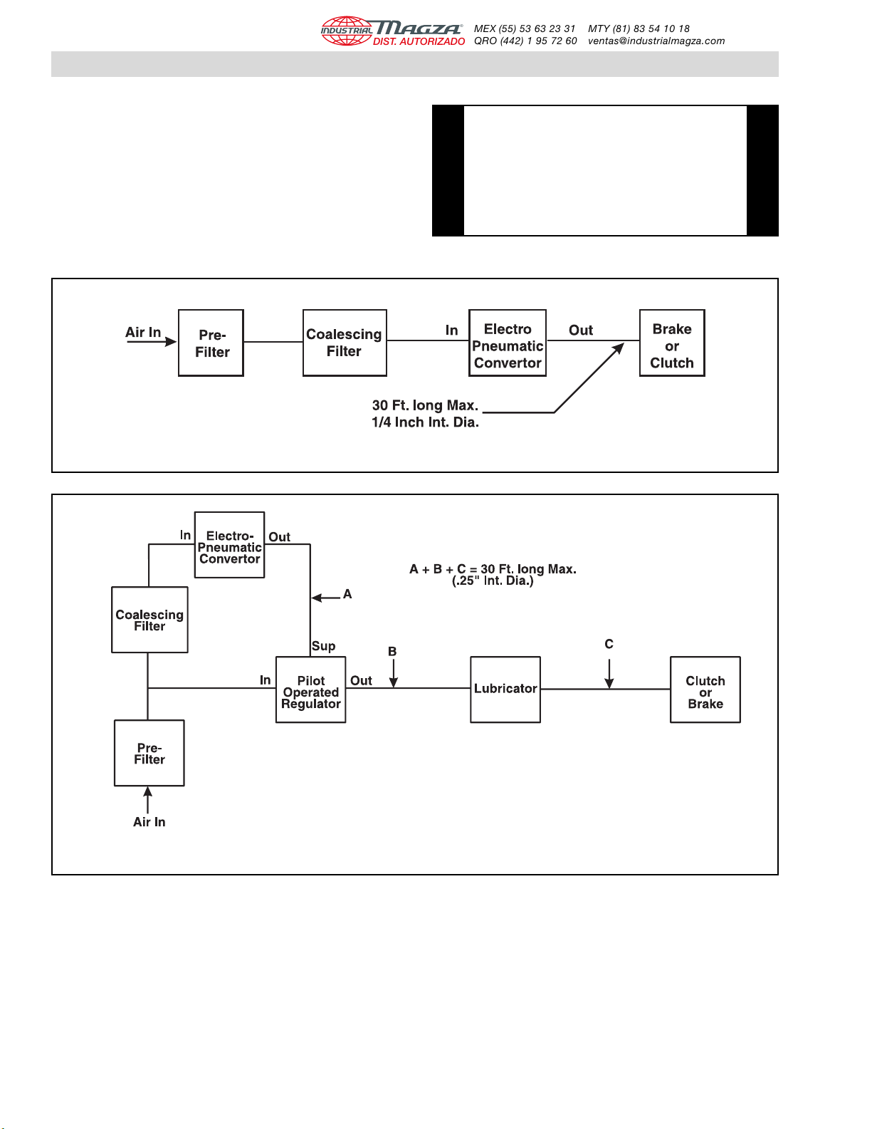
Nexen’s EN40-IS Electro-Pneumatic Converter converts
current input signals into corresponding pneumatic
signals. Normally the EN40-IS is used as part of a
Nexen-Nireco Intrinsically Safe Tension Control System,
or as an independent Electo-Pneumatic Converter,
controlled by an external signal from a Process Controller,
using an appropriate Zenier Barrier.
EN40-IS balances the force of a moving coil with the
force of a poppet valve, and amplifies the air flow and
pneumatic pressure passing through a fixed orifice by
means of the booster relay, resulting in a pneumatic
pressure proportional to the electric signal.
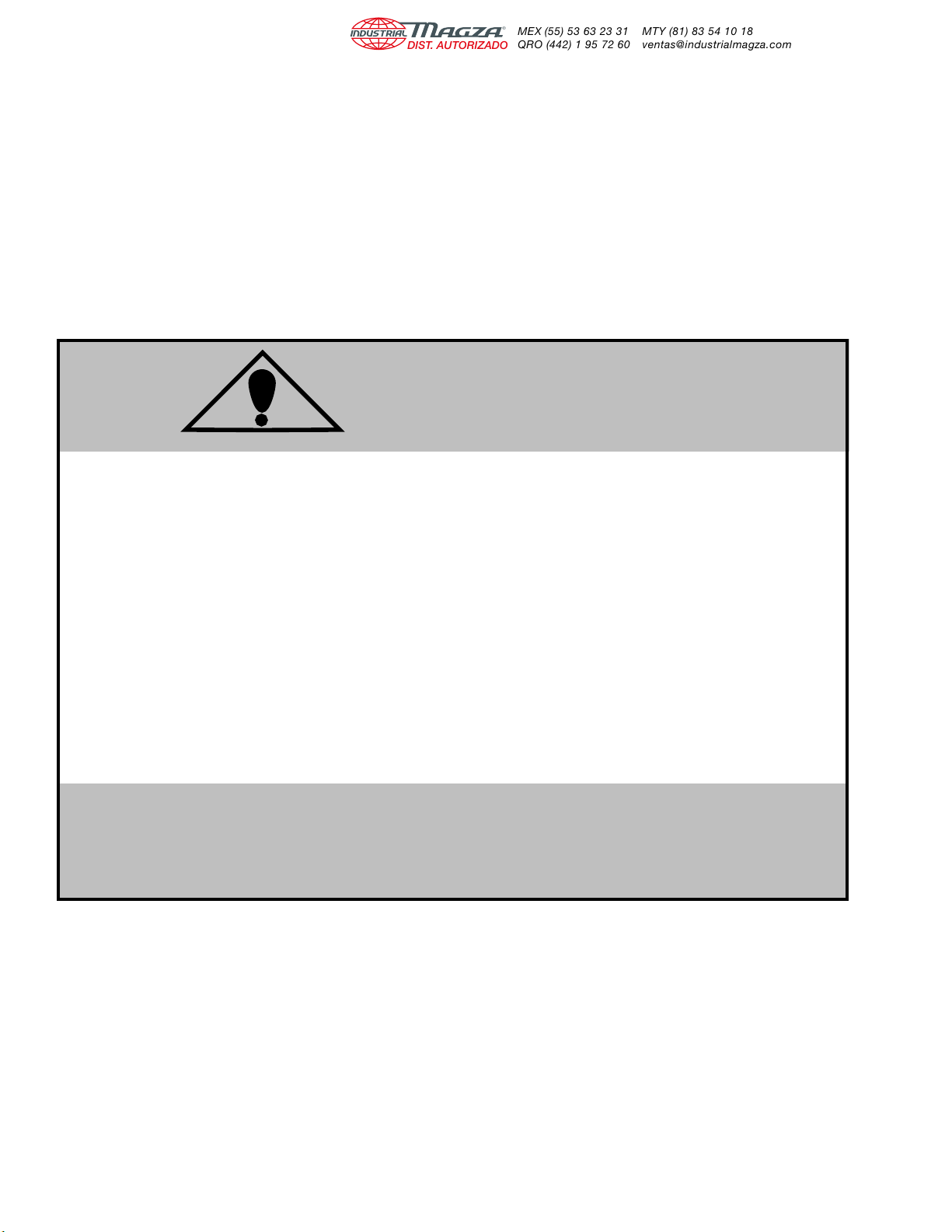
When current flows through the moving coil, a downward
force is induced proportionally to the current value. This
reduces the clearance between the poppet and seat,
causing back pressure to rise (See Figure 1).
Back pressure is too low to use as an output, but is used
as the pilot pressure for the Booster Section, increasing
both pressure and volume to provide a usable output. FIGURE 1
Spring
Plate
Fixed
Orifice
Moving
Coil
Permanent
Magnet
Poppet Seat
Pilot Pressure
Chamber
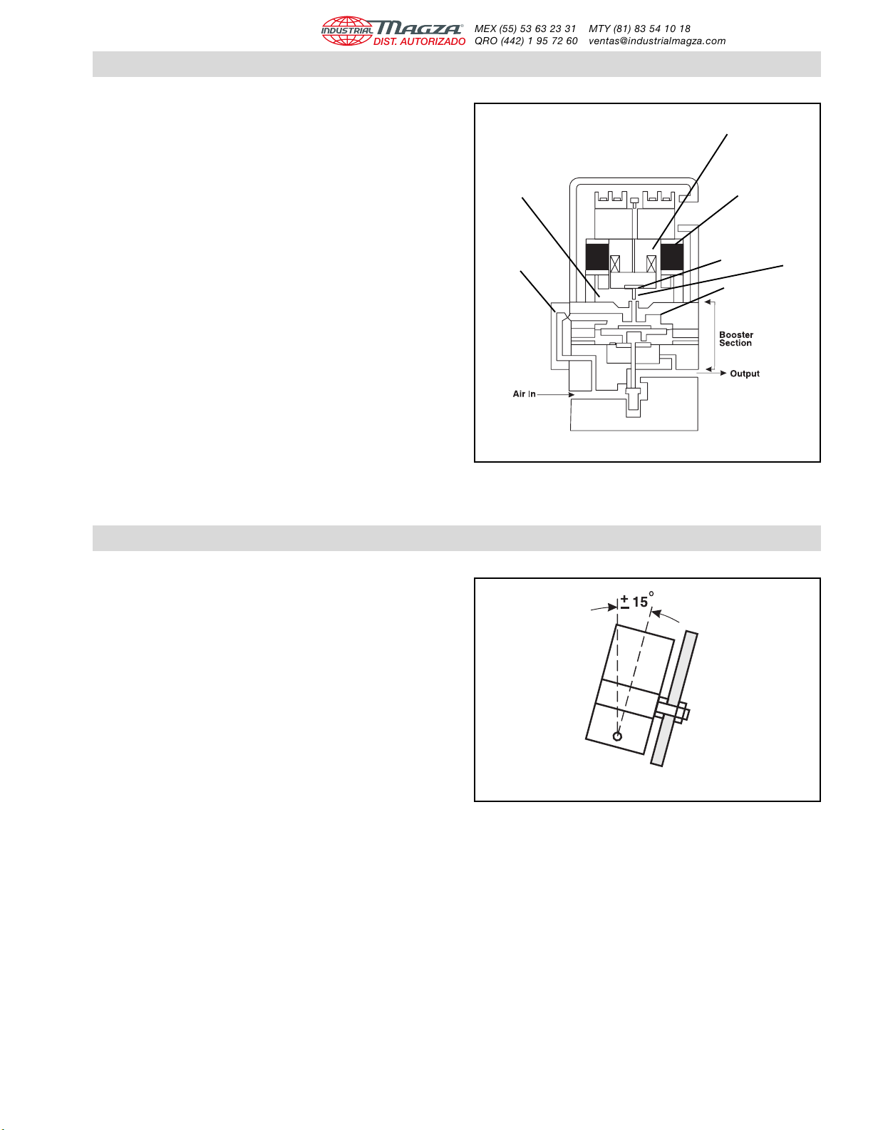
INSTALLATION
NOTE The EN40-IS must be mounted vertically within ±
15 degrees in a shock and vibration free area.
Locate the EN40-IS as close as possible to the
controlled element to guarantee quick precise
control (See Figure 2).
FIGURE 2
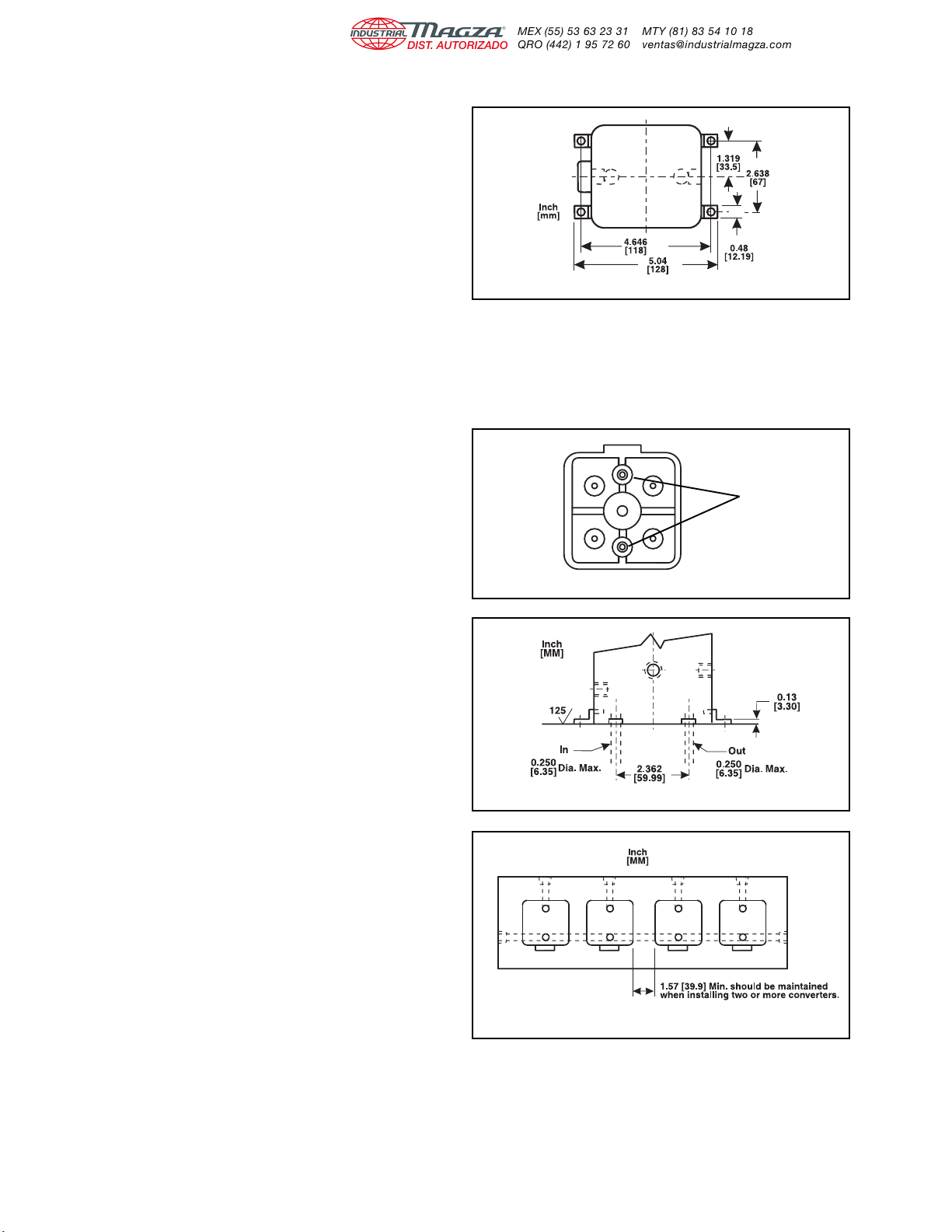
WALL MOUNTING
1. Drill two 0.28 In. [10 mm] diameter holes 4.57 In.
[166 mm] apart in the Mounting Panel. 2. Secure the EN40-IS to the Mounting Panel using the
cap screws provided in parts bag.
®
DIST. AUTORIZADO
MEX (55) 53 63 23 31
QRO (442) 1 95 72 60
MTY (81) 83 54 10 18