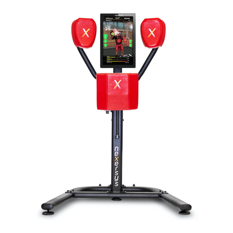
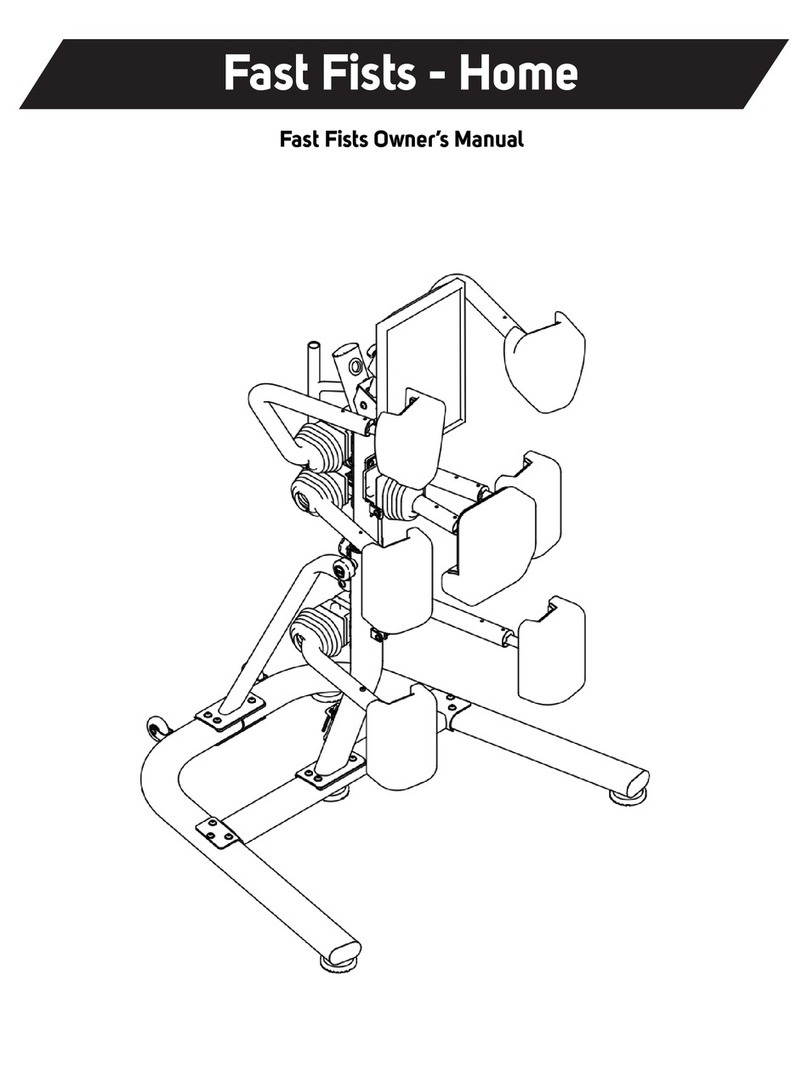
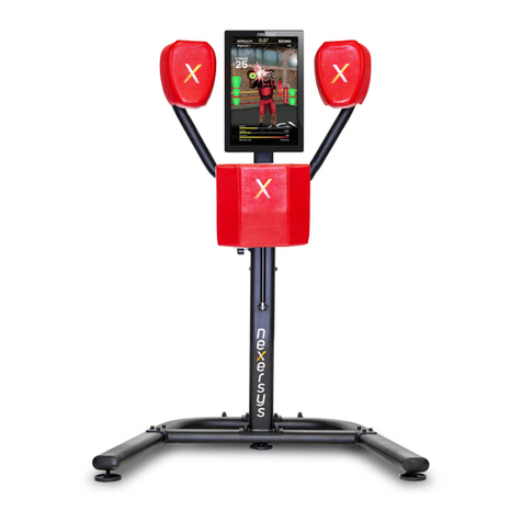
Nexersys PRO NXS-P User manual

Corporate Oces
500 San Marcos Street
Suite 201
Austin, TX 78702
www.nexersys.com
support@nexersys.com
(877) 785-3823
HARD BODY.
SHARP MIND.™
Nexersys Pro Model Assembly Manual
NXS-P
(P–120713)

Introduction ........................................................................................................................................................................................... 1
Important Safety Instructions.......................................................................................................................................................... 2
Hardware List & Images ..................................................................................................................................................................... 3
Parts Images .......................................................................................................................................................................................... 4
Parts Guide ............................................................................................................................................................................................. 5
Electronic Components ..................................................................................................................................................................... 6
Step 1: Spine Support Assembly..................................................................................................................................................... 7
Step 2: Spine Assembly ...................................................................................................................................................................... 8
Step 3: Pad Attachment Overview ................................................................................................................................................. 9
Step 4: Kick Pad Assembly................................................................................................................................................................. 11
Step 5: Body Pad Assembly............................................................................................................................................................... 12
Step 6: Head Pad Assembly .............................................................................................................................................................. 13
Step 7: Mount CPU and Monitor to Nexersys............................................................................................................................. 14
Step 8: Connect Accelerometer Cables ........................................................................................................................................ 15
Step 9: Connect Audio and Video Cables .................................................................................................................................... 16
Step 10: Connect AC Power Supply ............................................................................................................................................... 17
Step 11: Connect DC Power Cables to CPU and Monitor....................................................................................................... 18
Step 12: Insert SD Card....................................................................................................................................................................... 19
Step 13: Turn On Power...................................................................................................................................................................... 20
Final Inspection..................................................................................................................................................................................... 21
Contacts................................................................................................................................................................................................... 22
Table of Contents
Nexersys Pro Model Assembly Manual
NXS-P

1
NXS–P Assembly Manual
Nexersys Pro Model Assembly Manual
NXS-P
(P–120713)
Select where you are going to locate your Nexersys carefully. The best place for the machine is on a sturdy, level
surface. For best results, assemble the Nexersys in the location where you intend to use it. Allow a workout area of at
least 10ft by 6ft of free space for safe operation of the Nexersys. Below are a few basic tips that will make your assembly
of the Nexersys quick and easy. By using these principles, you can simplify each process and save yourself extra time
and eort.
To make the assembly process go faster, remember the location of the pieces you need for each step and thoroughly
read the assembly instructions for that step prior to starting assembly.
When tightening a locknut on a bolt, use a combination wrench to grip the locknut and ensure that it is fastened securely.
When attaching two pieces, gently lift and look through the bolt holes to help guide the bolt through the holes.
As a general rule, and for all bolts and nuts on the machine, turn bolts or nuts toward the right to tighten (clock-wise) and
left to loosen (counter clock-wise).
Tools
In order to construct your machine, you will need:
•CrescentWrench(Included)
•HexKeys(Included)
Unpacking Your Nexersys
Inside the Nexersys box you will nd: tools to help you with assembly, each unique piece, and all necessary hardware to
assemble the Nexersys. To make set-up easier, lay out each piece on the oor where it is visible and check the lists on
the following pages to make sure that the box contains the correct amount of each component. Try and remember where
you laid out each piece so that you can nd them quickly when you need them.
Introduction
Before Assembly

2
NXS–P Assembly Manual
Nexersys Pro Model Assembly Manual
NXS-P
(P–120713)
Be careful when dealing with larger Nexersys components, as they might require eort to lift and attach. Some steps
require two individuals. Have a second person assist you during assembly. Before using the Nexersys, make sure that all
screws have been tightened securely, as the Nexersys will endure shock forces during most workouts.
This icon means a potentially hazardous situation which, if avoided, could result in death or serious
injury.
Obey the following warnings:
Read and understand all warnings on this machine.
Carefully read and understand the Nexersys Assembly Manual.
• Keep bystanders and children away from the Nexersys you are assembling at all times.
• Do not assemble your Nexersys outdoors or in a wet or damp location.
• Make sure assembly is done in an appropriate work space away from foot trac and exposure to bystanders.
• Some components of the Nexersys can be heavy or awkward. Use a second person when doing the assembly
steps involving these parts. Do not do steps that involve heavy lifting or awkward movements on your own.
• Set up your Nexersys on a solid, level, horizontal surface.
• Do not try to change the design or functionality of this machine. This could compromise your safety and can
void the warranty.
• If replacement parts are necessary use only genuine Nexersys replacement parts and hardware. Failure to use
genuine replacement parts can cause a risk to users, keep the Nexersys from operating correctly and void the
warranty.
• Do not use or put the Nexersys into service until the machine has been fully assembled and inspected for
correct performance in accordance with this Assembly Manual.
ImportantSafetyInstructions

3
NXS–P Assembly Manual
Nexersys Pro Model Assembly Manual
NXS-P
(P–120713)
1–M12 160 mm Bolt
2–M8 20mm Bolt
M3.5 Lock Washer Hex Key, size = 5/32” Hex Key, size = 5 Hex Key, size = 6
28–M8 Flat Washer
(fastened to each pad)
28–M8 Lock Washer
(fastened to each pad)
2–M8 Flat Washer 1–M12 Nylock Nut
4–M3.5x5mm
Machine Screw 4–M3.5 Flat Washer
28–M8 20mm Bolt
(fastened to each pad)
2–M12 Flat Washer 8–M10 25mm Bolt 8–M10 Flat Washer
Hardware List & Images
A
E
I
M N O P
F G H
B C D
J K L

4
NXS–P Assembly Manual
Nexersys Pro Model Assembly Manual
NXS-P
(P–120713)
Parts Images
13
14
4
3
2
1
5
6
7
8 9
10
11
12
3

5
NXS–P Assembly Manual
Nexersys Pro Model Assembly Manual
NXS-P
(P–120713)
Parts Guide
Accelerometer Cables
Left Kick Pad
Center Body Pad
Right Head Pad
Spine
Rubber Gasket
DC Power Cable
Right Kick Pad
Right Body Pad (Kidney Pad)
Left Body Pad (Kidney Pad)
Left Head Pad
Base
Spine Support
Spine Handle
DescriptionQuantityItem
1 1
1
1
1
1
1
1
1
1
1
1
7
1
2
2
3
4
5
6
7
8
9
10
11
12
13
14

6
NXS–P Assembly Manual
Nexersys Pro Model Assembly Manual
NXS-P
(P–120713)
Electronic Components
22” LCD Monitor HDMI to DVI Cable
Audio Cable
AC Power Brick
SD Card
USB Cable
AC Cable
15 16
17
18
21
20
18

7
NXS–P Assembly Manual
Nexersys Pro Model Assembly Manual
NXS-P
(P–120713)
Step 1: Spine Support Assembly
C
D
3
Assembly
Parts Needed:
Base
Spine Support
Rubber Gasket
Hardware Needed:
M10 25mm Bolt (4)
M10 Flat Washer (4)

8
NXS–P Assembly Manual
Nexersys Pro Model Assembly Manual
NXS-P
(P–120713)
Additional Parts Needed:
Spine
Rubber Gasket
Spine Handle
A
B
B
G
C
D
3
5
E
F
1
Step 2: Spine Assembly
Hardware Needed:
M10 25mm Bolt (4)
M10 Flat Washer (4)
M12 Nylock Nut
M12 Flat Washer (2)
M12 160mm Bolt
M8 20mm Bolt (2)
M8 Flat Wahser (2)

9
NXS–P Assembly Manual
Nexersys Pro Model Assembly Manual
NXS-P
(P–120713)
Step 3: Pad Attachment Overview
Accelerometer cables must be connected to each pad before installation. Accelerometer cables are attached to the
pad mounting bracket at the factory before the unit is shipped. When detaching the accelerometer cable from each
individual arm, be sure not to let cable retract into the arm. Some accelerometer cables have tension due to coils in the
cable. Accelerometer cables must be properly attached to each pad for the unit to operate correctly. Use caution when
attaching the cable to prevent unnecessary force being applied to the accelerometer board mounted in
each pad.
Note: Hardware (bolts and washers) for attaching pads to unit comes fastened to each pad.
1
2
3
4
5
6
7

10
NXS–P Assembly Manual
Nexersys Pro Model Assembly Manual
NXS-P
(P–120713)
Step 3 Cont’d: Accelerometer
When attaching the accelerometer cable to the accelerometer board, make sure the cable is oriented properly and the
clip latches securely.

11
NXS–P Assembly Manual
Nexersys Pro Model Assembly Manual
NXS-P
(P–120713)
Parts Needed:
Left and Right Kick Pads
H
J
I
Step 4: Kick Pad Assembly
Hardware Needed:
M8 20mm Bolt (8)
M8 Lock Washer (8)
M8 Flat Washer (8)
Warning: Be sure to install left and right kick pads with edge padding toward center of unit.
Failure to do so will result in injury.

12
NXS–P Assembly Manual
Nexersys Pro Model Assembly Manual
NXS-P
(P–120713)
Parts Needed:
Left Body Pad
Right Body Pad
Center Body Pad
Step 5: Body Pad Assembly
Hardware Needed:
M8 20mm Bolt (12)
M8 Lock Washer (12)
M8 Flat Washer (12)
Be sure to install center body pad with edge padding toward bottom of unit. Failure to do so will
result in injury.

13
NXS–P Assembly Manual
Nexersys Pro Model Assembly Manual
NXS-P
(P–120713)
Parts Needed:
Left and Right Head Pads
H
J
I
Step 6: Head Pad Assembly
Hardware Needed:
M8 20mm Bolt (8)
M8 Lock Washer (8)
M8 Flat Washer (8)
Warning: Be sure to install left and right head pads with edge padding toward center of unit.
Failure to do so will result in injury.

14
NXS–P Assembly Manual
Nexersys Pro Model Assembly Manual
NXS-P
(P–120713)
KML
15
Step 7: Mount CPU and Monitor to Nexersys
Note: Both the lock washer and at washer are required for proper assembly.
Warning: Be sure to install washers per instructions to avoid potential damage to the CPU.

15
NXS–P Assembly Manual
Nexersys Pro Model Assembly Manual
NXS-P
(P–120713)
Step 8: Connect Accelerometer Cables
Note: Plug-in left to right when facing back of monitor. Make sure the clip on the acceleromater cable faces the monitor
when inserted.

16
NXS–P Assembly Manual
Nexersys Pro Model Assembly Manual
NXS-P
(P–120713)
16
VGA Port (Not Used)
20
20
17
Step 9: Connect Audio, Video & USB Cables

17
NXS–P Assembly Manual
Nexersys Pro Model Assembly Manual
NXS-P
(P–120713)
Step 10: Connect AC Power Supply
Note: Connect DC Cable from AC power supply to DC cable at base of Nexersys.
19
18

18
NXS–P Assembly Manual
Nexersys Pro Model Assembly Manual
NXS-P
(P–120713)
Step 11: Connect DC Power Cables to CPU and Monitor
Note: The DC cable is routed through the spine of the Nexersys Unit.
19
Table of contents
Other Nexersys Fitness Equipment manuals
Popular Fitness Equipment manuals by other brands
MAYHEM STRENGTH
MAYHEM STRENGTH Hack Squat Combo Assembly instructions
Wagan
Wagan Mini Cycle user manual
Slackline Industries
Slackline Industries SLACKSTAND manual
SPRI
SPRI XERBALL MEDICINE BALL Exercise guide

MONSTER FITNESS
MONSTER FITNESS AF1001 Assembly instructions
FOLLO FUTURA
FOLLO FUTURA FOLLO DIEM G manual
