NEXIS VW8208 User manual

NEXIS Video Wall Processor
User’s Manual
User’s Manual
Version1.6
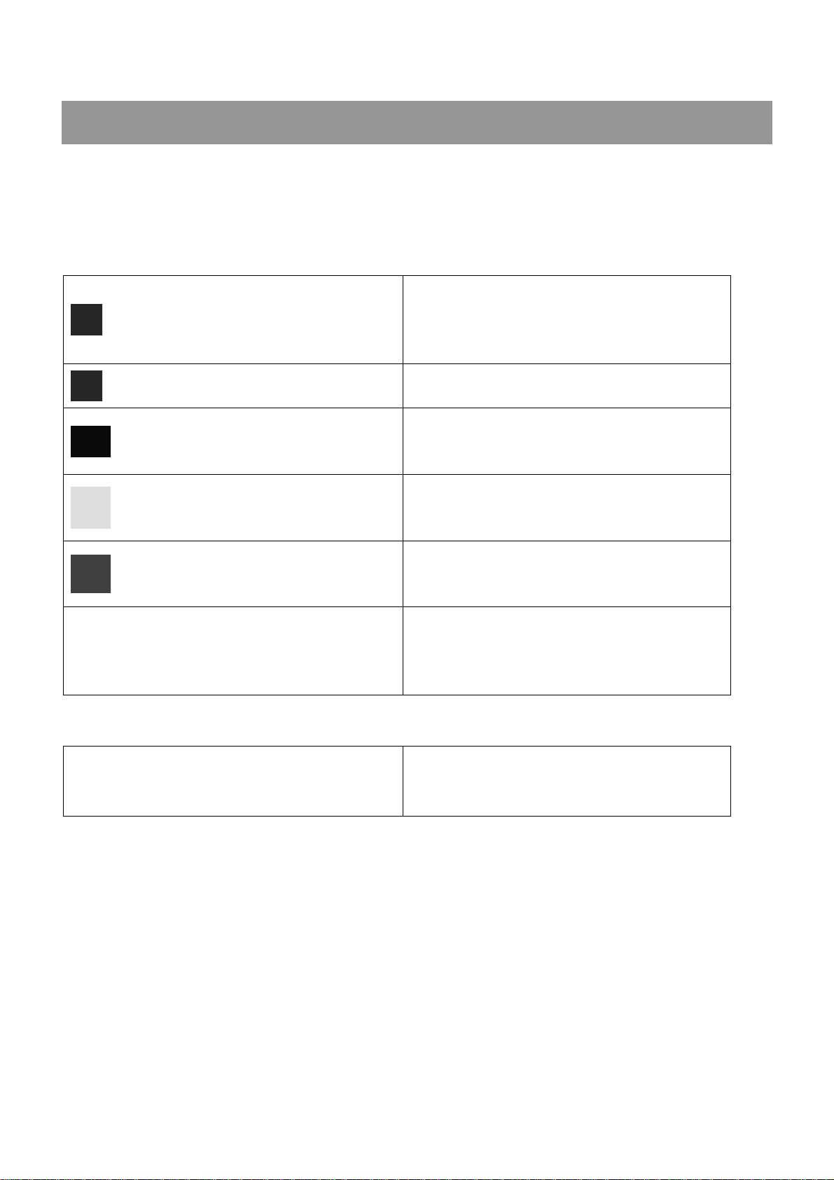
The indications of symbols
■Safety instructions
Some symbols pointing out the potential risk of injury and property loss are used in the instructions and
devices, to help you use the devices safely and properly. Symbols and their indications are as follows. Please
make sure that you have known these instructions before reading the manual.
Remind users to operate and maintenance
according to the instructions attached to the
devices. If ignoring this information, it may
cause death or injury due to wrong operations.
Remind users that uninsulated dangerous
voltage in devices may lead to electric shock.
CE certification means that the product has
reached the safety requirements specified by
EU regulations, users can be assured.
SGS certification means that the product has
reached the quality standards of the world's
largest Societe Generale de Surveillance.
This product has passed ISO9001
international quality certification
(certification bodies: Rheinland TUV).
WARNING: To avoid electric shock, do not open
the cover, and do not place unnecessary portion
in the chassis. Please contact qualified service
personnel.
■General information indications
Information that may lead to an unsuccessful
operation or setting and other relevant
information needed to be noticed is listed.

Important notes
Warning
To ensure reliable use of devices and safety of personnel, please observe the following items in
the installation, use and maintenance.
Notes in installation
◆Do not use this product in the following places: Where exists dust, smoke, conductive dust,
corrosive gases or flammable gases; where exposes to high temperature, condensation or wind and
rain; where exists vibration and shock. Electric shock, fire, incorrect operation will also lead to product
damage and deterioration;
◆During screw hole processing and wiring, metal chips and wire heads shall not be dropped into
ventilation holes of controllers, which may cause a fire, malfunction or incorrect operation;
◆When the installation work is done, make sure that no foreign body is left on the surface of
ventilation, including contact paper and other packaging materials, otherwise it may lead to poor
run-time heat, causing a fire, malfunction or incorrect operation;
◆Avoid wiring or inserting/pulling plugs in charged state, otherwise it may easily lead to electric shock
or cause damage to the circuit;
◆Installation and wiring must be solid and reliable, poor contact may result in incorrect operation;
◆For application in occasions with severe interference, shielded cables should be used to input and
output high-frequency signal so that anti-interference performance of the system could be improved.
Notes in wiring
◆All of the external power supply must be cut off before carrying out installation, wiring and other
operations, or it may cause electric shock or equipment damage;
◆This product is grounded through the grounding conductor of the power cord. In order to avoid
electric shock, the grounding conductor must be connected to earth. Before connecting the input or
output terminals of the product, make sure that the product is properly grounded;
◆Once wiring is completed, foreign matters should be immediately removed. Please cover the
terminal covers of product before power connection to avoid electric shock;
Notes in operation and maintenance
◆Do not touch the terminal when power is on, or it may cause electric shock or incorrect operation;
◆Perform cleaning and terminal tightening when power is off, for these operations may cause
electric shock when power is on;
◆Perform connection, removal or other operations of the communication signal cables and the cables
of expansion board or control unit after power is off, or it may cause equipment damage or incorrect
operation;
◆Do not disassemble the equipment, so as not to damage the internal electrical components;
◆Always read the manual, after security fully recognized, changing the program, commissioning,
starting and stopping operations after security is fully recognized;
◆Button batteries must be replaced when the power is off. When you indeed need to replace the
button batteries with the power on, the operation should be performed by a qualified electrical

technician wearing insulated gloves.
Notes in product obsolescence
◆Explosive electrolytic capacitors: It may cause explosion when electrolytic capacitor on the circuit
board burns;
◆Please collect and process separately, it cannot be put in the life garbage.
◆Please process it as industrial waste, or process it in accordance with local environmental
regulations.
◆Please turn off or disable the Loop / Daisy Chain function on the Video Wall Screens when
connecting to the VW Series chassis. This function might cause conflict to VW Series input and output
signal. Using VW series controller with Loop / Daisy Chain function is considered as improper
connection, Warranty will be Voided.
◆In case of using signal converter, only use the active converter to maintain proper signal and
electrical characteristic. Passive converter might cause signal loss or power surges.
Notes in Specialized Video Wall Screens connection
The warranty only covers failures or malfunctions that occur during the warranty period and under
normal use conditions as well as any material or workmanship defect.
The warranty will not apply to or be valid under conditions including but not limited to the following:
Notes in Warranty Void
We may amend, update or otherwise change, at any time and without prior notice, any or all of
the Terms of Use, the conditions and/or the provisions included in this document.
The serial number of the NEXIS product, components or accessories has been altered,
canceled, removed, or otherwise not valid as identified by NEXIS;
The product has been tampered with, repaired and/or modified by non-authorized personnel;
The product warranty seals have been broken or altered;
There is damage caused by natural disaster, intentional or unintentional misuse, abuse,
neglect, acts of war, improper maintenance, or use under abnormal conditions;
There is damage caused by accidental drops, spills, fire, or power surges.
There is damage from improper installation, improper connection, or use of parts and/or
components not manufactured or sold by NEXIS;
There is damage from use outside of the operation or storage parameters or environment
detailed in the User's Manual or reasonably acceptable for similar product usage models
deemed industry standard best practices;

Contents
Chapter One Overview............................................................................................................................1
1.1Product Equipment...................................................................................................................1
1.2 function features......................................................................................................................2
1.3 cabinet installation ..................................................................................................................2
Chapter Two Hardware Introductions .....................................................................................................3
2.1 VW8208 panel diagram............................................................................................................3
2.2 VW8316 panel diagram............................................................................................................3
2.3 VW8736 panel diagram............................................................................................................4
2.4 VW81272 panel diagram..........................................................................................................5
2.5 Link of matrix and peripherals................................................................................................7
2.5.1 Input interface description................................................................................................7
2.5.2 Output interface description.............................................................................................7
2.5.3 Control board communication port and link method........................................................7
2.5.4 Matrix RS-232 control interface.......................................................................................7
2.5.5 Link of matrix and control computer.................................................................................7
2.5.6 Matrix KEYBOARD interface...........................................................................................7
2.5.7 Link of matrix and extended keyboard.............................................................................8
2.5.8 Matrix Ethernet Interface .................................................................................................8
2.5.8.1 Hardware linking method.......................................................................................8
2.5.8.2 Connection Method Description of RJ45 Ethernet Port straight-through Line and
Cross-line ..........................................................................................................................8
2.5.9 HDMI port description......................................................................................................9
2.5.10 DVI port description.......................................................................................................9
2.5.11 DB15 interface description...........................................................................................10
2.5.12 DB15 male socket transfer cable(S terminal, RCA head)............................................10
2.5.13 DB15 male socket transfer cable definition .................................................................11
Chapter Three Control Panel Operating Instructions............................................................................12
3.1 Panel description...................................................................................................................12
3.1.1 VW8208 Panel...............................................................................................................12
3.1.2 VW8316 Panel...............................................................................................................12
3.1.3 VW8736 Panel...............................................................................................................13
3.1.4 VW81272 - VW8144144 Panel......................................................................................13
3.2 Input boards ...........................................................................................................................18
3.2.1 VW7804 HDMI Input board function features................................................................18
3.2.2 VW7604 DVI Input board function features...................................................................18
3.2.3 VW7514 HDBaseT twisted pair input board function features.......................................19
3.2.4 VW7104 VGA Input board function features..................................................................19
3.2.5 VW7404 SDI Input board function features...................................................................19
3.2.6 VW7704 Optical fiber input board function features......................................................19
3.2.7 VW7002 RJ45 Input card Functions and Features........................................................19

3.3 Output boards ........................................................................................................................20
3.3.1 VW8804 HDMI stitching output board function features................................................20
3.3.2 VW8604 DVI switching output board function features .................................................20
3.3.3 VW8514 HDBaseT twisted pair stitching output board function features......................20
3.3.4 VW8704 Optical fiber stitching output board function features......................................20
3.4 Preview boards ......................................................................................................................20
3.4.1 VW-PVW04 Preview board function features................................................................20
3.5 Control boards .......................................................................................................................21
3.5.1 VW-CTN04 Control board function features..................................................................21
3.5.2 VW-CTN05 Advanced control board function features..................................................21
3.6 specifications and technical parameters.............................................................................22
Chapter Four Instructions......................................................................................................................31
4.1 NEXIS Processor instructions..............................................................................................31
4.2 Splicer instructions ...............................................................................................................39
Chapter Five Software ..........................................................................................................................41
5.1 Connection .............................................................................................................................41
5.2 Interface introduction............................................................................................................42
5.3 Drag &Drop to change the video source.............................................................................45
5.4 Change the output window size...........................................................................................45
5.5 Save and Call the profile.......................................................................................................46
5.6 Matrix switching control(Seamless output card is needed)..............................................47

www.nexisgroup.com.tw
NEXIS video wall processor User’s Manual
X9 Series Hybrid Splicing Matrix User’s Manual
X9 Series Hybrid Splicing Matrix User’s Manual
X9 Series Hybrid Splicing Matrix User’s Manual
X9 Series Hybrid Splicing Matrix User’s Manual
X9 Series Hybrid Splicing Matrix User’s Manual
1
Chapter One Overview
NEXIS video wall processor can realize graphics
processing and seamless switching flexibly. The
matrix adopts high-performance hardware design,
perfectly supports a variety of high-definition
digital /analog signal switching and processing,
and supports two-way RS-232, two-way IR signal
assigned switching function. It can also divide a
completed image signal into several signals
assigned to several different display unites,
forming a large display screen to display dynamic
images. It provides a one-stop solution for various
industries to assign, switch and process a variety
of video and control signals, which can be widely
used in radio and television engineering,
multimedia conference room, large-screen
display engineering, television teaching,
intelligent traffic management centers, command
and control centers and other places.
NEXIS video wall processor contains
VW8208,VW8316, VW8736, VW81272,
VW8144144 and other models, its signal input/
output interface contains HDMI, DVI, VGA,
HDBaseT, SDI, optical fiber and other video
interfaces. Leading all-digital signal processing
technology ensures undistorted processing,
sending top quality screen to the display terminal.
With customized configuration of various types of
the same or different input/output boards, single
interface type or multi interface type of matrix can
be formed, such as optical fiber matrix, HDMI
matrix, DVI matrix, CAT5 matrix, VGA matrix,
YUV matrix, Video matrix and so on.
NEXIS video wall processor provides a variety
of control modes, with remote control operation,
RS-485 extended keyboard, but also provides two
standard RS-232 communication interfaces and
network ports, convenient for users to coordinate
it with various remote control devices.
1.1Product Equipment
VW8208
VW8316
VW8736
uVW7804 input board (HDMI signal input)
uVW7604 input board (DVI signal input)
uVW7514 twisted pair input board (HDBaseT
signal input)
uVW7104 input board (CV, YPbPr, VGAI signal
input)
uVW7404 input board (SDI signal input)
uVW7704 optical fiber input board (OPTICAL
FIBER signal input)
Video wall output boards:
uVW8804 stitching output board (HDMI signal
output)
uVW8604 stitching output board (DVI, RGB
signal output)
uVW8514 twisted pair stitching output board
(HDBaseT signal output)
uVW8704 optical fiber stitching output board
(OPTICAL FIBER signal output)
Preview board:
uVW-PVW04 preview board (video signal
output)
Control board:
uVW-CTN04 control board
uVW-CTN05 advanced control board
VW81272
VW8144144
Modular video wall processor can be composed
of any of the following input and output boards:
Input boards:

www.nexisgroup.com.tw
NEXIS video wall processor User Manual
2
1.2 function features
All digital switching, each seamless output
board can realize real-time seamless switching;
Each stitching output board can realize video
stitching; picture windows in full screen can zoom,
overlay and roam arbitrarily;
Preview board can realize previewing videos by
group and switching function;
Support DVI 1.0 protocol, in line with HDCP1.3,
compatible with HDMI 1.3a;
Support hot plug, support audio and video
signal switching together;
Digital audio and analog audio in HDMI input
board can be input selectively, digital audio and
analog audio in HDMI output board can be output
simultaneously;
Support PC software control switching and
EDID management;
HDBaseT input/output signals support
embedded (or local) two-way RS-232 and
two-way IR signals, and can switch optionally with
video signal or switch separately. They also
support POC providing external power supply
(VW8736 and its upgrades support POC);
◆Flexible control with infrared remote control,
RS485, RS232 communication interface and
network ports, and can be controlled by distant
HDBaseT / optical fiber serial ports, convenient
for users to coordinate it with various remote
control devices;
◆Support firmware upgrade online;
◆support intelligent control matrix fan operation;
◆SDI input board has looping out function;
◆VW8736 and its upgrades have redundant
power supply design;
◆Plug-in board structure design, flexibly
allocate input/output signal type and signal
channel number.
1.3 cabinet installation

www.nexisgroup.com.tw
NEXIS video wall processor User Manual
3
Chapter Two Hardware Introductions
2.1 VW8208 panel diagram
VW8208 front panel:
VW8208 back panel:
2.2 VW8316 panel diagram
VW8316 front panel:
VW8316 back panel:

www.nexisgroup.com.tw
NEXIS video wall processor User Manual
4
2.3 VW8736 panel diagram
VW8736 front panel:
VW8736 back panel:

www.nexisgroup.com.tw
NEXIS video wall processor User Manual
5
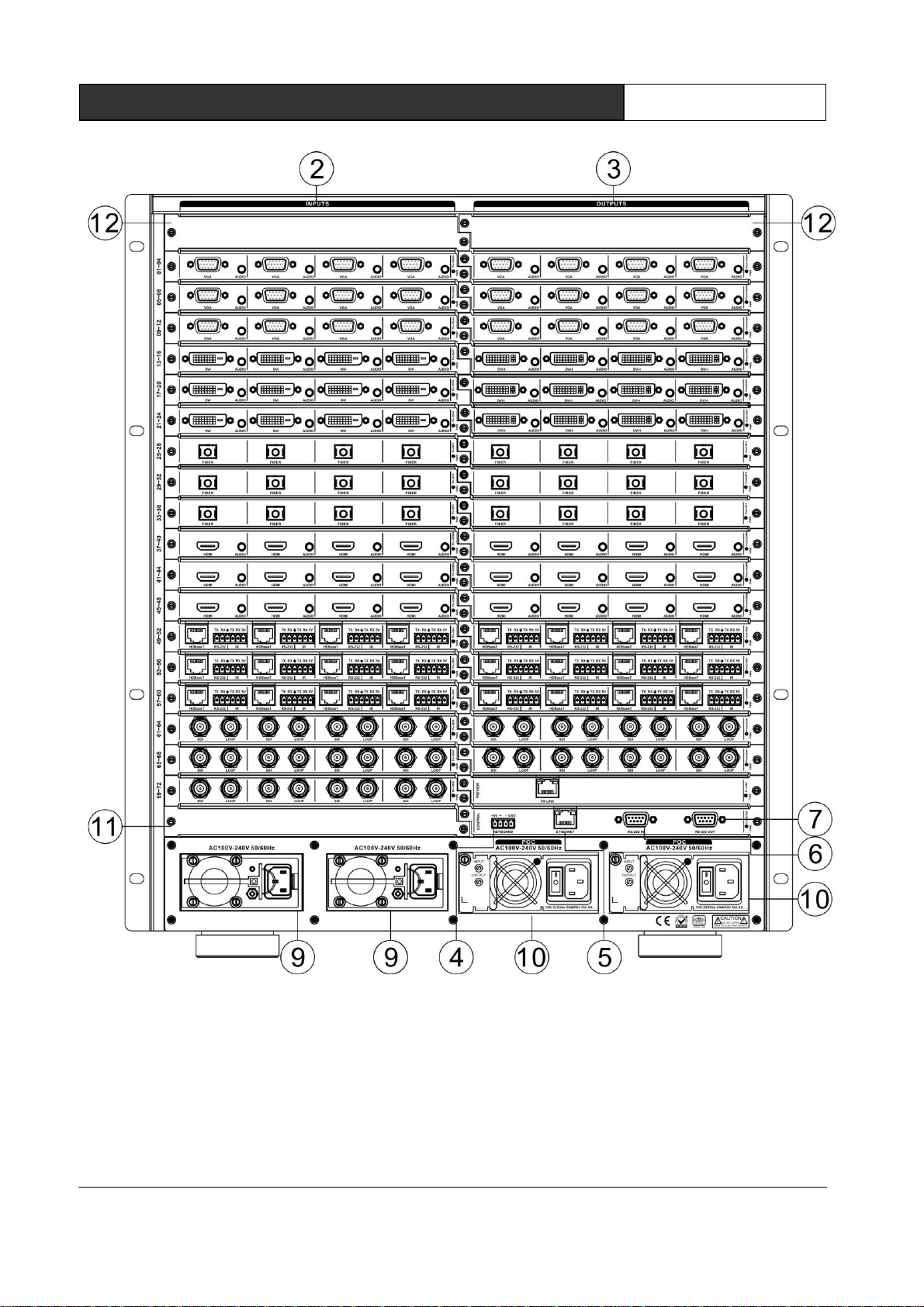
2.4 VW81272 - VW8144144 panel diagram
VW81272 front panel
www.nexisgroup.com.tw
NEXIS video wall processor User Manual
6
VW81272 Rear Panel:
VW8144144 Panel : In same configuration manner with taller casing and I/O Slot
www.nexisgroup.com.tw
NEXIS video wall processor User’s Manual
X9 Series Hybrid Splicing Matrix User’s Manual
X9 Series Hybrid Splicing Matrix User’s Manual
X9 Series Hybrid Splicing Matrix User’s Manual
X9 Series Hybrid Splicing Matrix User’s Manual
X9 Series Hybrid Splicing Matrix User’s Manual
7
2.5 Link of matrix and peripherals
2.5.1 Input interface description
The input interface is composed of VW7604,
VW7804, VW7514, VW7104, VW7404 and V
W7704 input board, enable to combine variou
s input signal formats arbitrarily.
2.5.2 Output interface description
The output interface is composed of VW8604,
VW8804, VW8514, VW8704 stitching output
board, enable to combine various input signal
formats arbitrarily.
2.5.3 Control board communication port
and link method
NEXIS modular matrix provides standard
RS-232 serial communication ports, in addition to
realize switching operations with infrared remote
control, it can also control by using a variety of
control systems (such as PC, NEXIS control
systems, control systems of other manufacturers,
etc.).
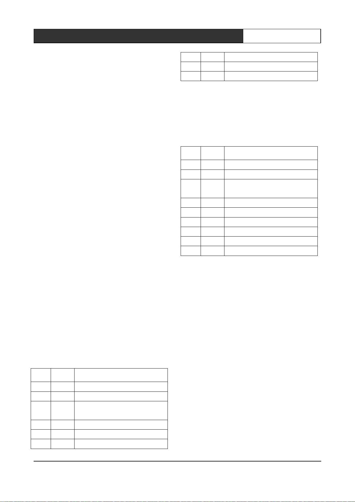
2.5.4 Matrix RS-232 control interface
Modular matrix provides two-way RS-232 serial
interfaces (a DB9 female connector, a male DB9
connector), you can use this interface to control
the matrix. Pin description of RS-232 port DB9
female connector is as follows:
pin
signal
description
1
-
-
2
TXD
RS-232 protocol, sending data
3
RXD
RS-232 protocol, receiving
data
4
-
-
5
GND
Signal ground
6
-
-
7
-
-
8
-
-
9
-
-
Pin description of RS-232 port DB9 male
connector is as follows:
pin
signal
description
1
-
-
2
RXD
RS-232 protocol, sending data
3
TXD
RS-232 protocol, receiving
data
4
-
-
5
GND
Signal ground
6
-
-
7
-
-
8
-
-
9
-
-
2.5.5 Link of matrix and control
computer
With RS232 cable to link the computer's serial
communication port (COM1 or COM2) and the
matrix cabinet’s RS-232 communication port, and
use control command to control. For more details,
refer to Chapter five, Instructions.
2.5.6 Matrix KEYBOARD interface
The matrix provides one-way KEYBOARD
interface, it is used to link with extended keyboard

www.nexisgroup.com.tw
NEXIS video wall processor User Manual
8
VIS-MKB100 so that you can switch the channels
of the matrix. KEYBOARD is a four-foot 3.8mm
phoenix interface, its pin description is as follows:
pin
signal
description
1
+5V
Output DC5V/1A, enable to
provide power for MKB100
2
+
RS-485 protocol, DATA+
3
-
RS-485 protocol, DATA-
4
GND
Signal ground
2.5.7 Link of matrix and extended
keyboard
Based on screen printing, correspondingly
connect matrix cabinet KEYBOARD interface with
extended keyboard VIS-MKB100’s MATRIX
interface, then you can control the matrix. For
more details, refer to User's Manual of MKB100
Matrix Keyboard.
2.5.8 Matrix Ethernet Interface
2.5.8.1 Hardware linking method
There are two ways to link matrix with
Ethernet adapter hardware
1) cross-connect method
Matrix and control computer is directly
connected via CAT5 crossover
cable.
2) through-connect method
Matrix and Ethernet switchboard or
concentrator is connected via CAT-5
straight-through cable.
2.5.8.2 Connection Method Description
of RJ45 Ethernet Port straight-through
Line and Cross-line
The system adopts CAT-5 (super 5-type line)
as wires, using RJ-45 connector (commonly
known as crystal head) of CAT-5 to connect
network devices. Standard twisted-pair
connection method is specifically regulated,
aiming to ensure the symmetry of cable connector
layout so that the interference between the cables
within the connector can be offset. Super 5-type
line in general has four pairs of wires twisted
together, with different colors.
There are two ways to connect twisted pair:
EIA / TIA 568B standard and EIA / TIA 568A
standard.
www.nexisgroup.com.tw
NEXIS video wall processor User Manual
9
T568A line order
1
2
3
4
5
6
7
8
White Green
Green
White Orange
Blue
White Blue
Orange
White Brown
Brown
T568B line order
1
2
3
4
5
6
7
8
White Orange
Orange
White Green
Blue
White Blue
Green
White Brown
Brown
Straight-through line: both ends are connected in
T568B line order.
Crossover line: one end is connected in T568A
line order, the other end is connected in T568B
line order.
2.5.9 HDMI port description
HDMI-A Type Line description:
Users can connect a variety of computer
signals, audio and video signal equipments, such
as DVD players, desktop computers, graphics
workstations, and number displays in different
occasions, output terminals can be connected to
the projector, VCRs, computer monitors,
amplifiers and so on.
PIN
Function
1
TMDS Data2+
2
TMDS Data2 Shield
3
TMDS Data2–
4
TMDS Data1+
5
TMDS Data1 Shield
6
TMDS Data1–
7
TMDS Data0+
8
TMDS Data0 Shield
9
TMDS Data0–
10
TMDS Clock+
11
TMDS Clock Shield
12
TMDS Clock–
13
CEC
14
Reserved (in cable but N.C. on device)
15
SCL
16
SDA
17
DDC/CEC Ground
18
+5V Power
19
Hot Plug Detect
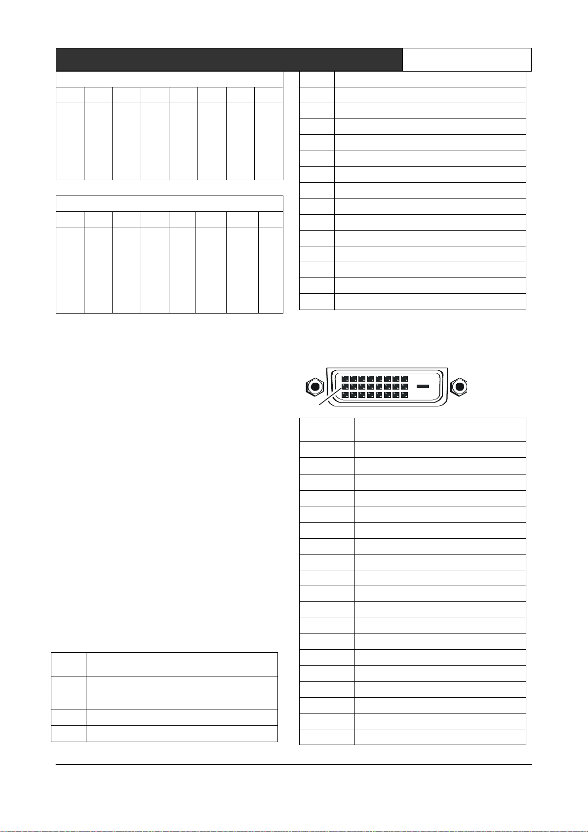
2.5.10 DVI port description
DVI-D Dual Link interface description
1
9
8
17
24
PIN
Function
1
T.M.D.S.Data2-
2
T.M.D.S.Data2+
3
T.M.D.S. Data 2/4 Shield
4
T.M.D.S. Data 4-
5
T.M.D.S. Data 4+
6
DDC Clock
7
DDC Data
8
No Connect
9
T.M.D.S.Data1-
10
T.M.D.S.Data1+
11
T.M.D.S.Data1/3 Shield
12
T.M.D.S.Data3-
13
T.M.D.S.Data3+
14
+5V Power
15
Ground (for +5V)
16
Hot Plug Detect
17
T.M.D.S. Data 0-
18
T.M.D.S. Data 0+
19
T.M.D.S. Data 0/5 Shield

www.nexisgroup.com.tw
NEXIS video wall processor User Manual
10
20
T.M.D.S.Data5-
21
T.M.D.S.Data5+
22
T.M.D.S. Clock Shield
23
T.M.D. S. Clock +
24
T.M.D.S .Clock-
2.5.11 DB15 interface description
Pin description of component video DB15 port is
as follows:
PI
N
VGA
Compone
nt
S-Vide
o
Composi
te
1
RED
Pr
N/C
N/C
2
GREEN
Y
N/C
N/C
3
BLUE
Pb
N/C
N/C
4
ID2
N/C
N/C
CVBS
5
GND
GND
N/C
GND
6
GND
GND
GND
N/C
7
GND
GND
GND
N/C
8
GND
N/C
N/C
N/C
9
N/C
N/C
Y
N/C
10
GND
N/C
N/C
N/C
11
N/C
N/C
C
N/C
12
SDA
N/C
N/C
N/C
13
HSYNC
N/C
N/C
N/C
14
VSYNC
N/C
N/C
N/C
15
SCL
N/C
N/C
N/C
Pin description of VGA video output board is as
follows:
pin
signal
description
1
RED
red primary
2
GREEN
green primary
3
BLUE
blue primary
4
ID2
address code 2
5
GND
ground
6
RGND
red ground
7
GGND
green ground
8
BGND
blue ground
9
KEY
reserved
10
SGND
digital ground
11
ID0
address code 0
12
SDA
data pin
13
HSYNC
horizontal
synchronization
14
VSYNC
vertical synchronization
15
SCL
clock signal
2.5.12 DB15 male socket transfer
cable(S terminal, RCA head)

www.nexisgroup.com.tw
NEXIS video wall processor User Manual
11
2.5.13 DB15 male socket transfer cable
definition
VGA input board of matrix supports the input
of analog, composite video and component video;
VGA output board supports the output of analog,
composite video and component video. If users
need input or output component video signal, they
need connect DB15 male socket transfer cable(S
terminal, RCA head). The two kinds of connection
are different, two things should be noticed:
1. the connection of VGA input board: support
VGA, CVBS and YPbPr signal; when CVBS and
YPbPr signal are needed, only three lines of
DB15 male socket transfer cable terminal are
useful. As shown above, the connection of YPbPr
signal is Y attached to green line, Pb attached to
blue line, Pr attached to red line; For CVBS signal,
green line is the right one, signals can be
recognized automatically, no setting is needed
(VGA input port can access three signals, but one
port can only attach to one signal a time).
2, the connection of VGA output board: support
VGA, CVBS and YPbPr signal; when CVBS and
YPbPr signal are needed, four lines of DB15 male
socket transfer cable terminal are useful. As
shown above, the connection of YPbPr signal is Y
attached to green line, Pb attached to blue line, Pr
attached to red line; For CVBS signal, only yellow
line is the right one. VGA or YPbPr signal output
requires instruction setting; CVBS output has
always been on, no setting is needed.

www.nexisgroup.com.tw
NEXIS video wall processor User Manual
12
Chapter Three Control Panel Operating
Instructions
3.1 Panel description
3.1.1 VW8208 panel
VW8208 front panel:
VW8208 back panel:
3.1.2 VW8316 panel
VW8316 front panel:

www.nexisgroup.com.tw
NEXIS video wall processor User Manual
13
VW8316 back panel:
3.1.3 VW8736 panel
VW8736 front panel:

www.nexisgroup.com.tw
NEXIS video wall processor User Manual
14
VW8736 back panel:
This manual suits for next models
3
Table of contents
Popular Media Converter manuals by other brands


H&B
H&B TX-100 Installation and instruction manual

Bolin Technology
Bolin Technology D Series user manual

IFM Electronic
IFM Electronic Efector 400 RN30 Series Device manual

GRASS VALLEY
GRASS VALLEY KUDOSPRO ULC2000 user manual

Linear Technology
Linear Technology DC1523A Demo Manual

Lika
Lika ROTAPULS I28 Series quick start guide

Weidmuller
Weidmuller IE-MC-VL Series Hardware installation guide

Optical Systems Design
Optical Systems Design OSD2139 Series Operator's manual

Tema Telecomunicazioni
Tema Telecomunicazioni AD615/S product manual

KTI Networks
KTI Networks KGC-352 Series installation guide

Gira
Gira 0588 Series operating instructions

Lika
Lika SFA-5000-FD user guide