Nexo MSUB12 Series User manual

DP5252-01-DI
MSUB12-I
User Manual

TABLE OF CONTENTS
Page 2 / 20 MSUB12-I
TABLE OF CONTENTS
TABLE OF CONTENTS___________________________________________________________________ 2
WARNINGS ____________________________________________________________________________ 3
DESCRIPTION__________________________________________________________________________ 4
SETTING RANGE _______________________________________________________________________ 5
MSUB12 RIGGING ______________________________________________________________________ 9
MSUB12 - ACCESSORIES _______________________________________________________________ 12
ARRAY EQ____________________________________________________________________________ 14
MAINTENANCE________________________________________________________________________ 15
TECHNICAL SPECIFICATIONS ___________________________________________________________ 17
USER NOTES _________________________________________________________________________ 18
EU Conformity declaration
We,
NEXO SA
ZA DU PRE DE LA DAME JEANNE
60128 PLAILLY –France
Declare under our sole responsibility that the product
Type
Serial number
Loudspeaker
MSUB12
On the product
Is in conformity with the provisions of the following directive
including all applicable amendments:
2014/35/UE (Low Voltage Directive)
Applied rules and standards:
Plailly, August 2020
EN 13155, EN 62368
Joseph CARCOPINO, R&D Director

WARNINGS
MSUB12-I Page 3 / 20
WARNINGS
PRECAUTIONS
-
repairable part.
If the system seems to be malfunctioning or damaged, stop using it at once and have it repaired by a NEXO qualified technician.
Do not expose the system directly to the sun or to the rain, do not immerse it into fluids, do not place objects filled with liquid on the
system. If a liquid gets into the system, please have it inspected by a NEXO qualified technician.
The connection should be performed by qualified technician, by ensuring that power is off.
Operating temperature with temperate climate: 0°C to +40°C (+32°F to +104); -20°C à +60°C (-4°F to +140°F) for storage.
SAFETY INFORMATIONS
Read this manual before using the speaker.
Keep this manual available for further reference.
Observe all warnings and cautions.
Please check the NEXO Web site nexo-sa.com to get the most up-to-date version of this manual.
Ensure you are aware of the safety rules applying to rigging, stacking or installing on tripod or speaker stand. Failure to observe
these rules may expose persons to potential wounds or even death.
Only use the system with accessories specified by NEXO.
Please always consult a NEXO-accredited technician if the installation needs architectural works and observe following precautions:
Mounting Precautions:
- Please select screws and mounting location supporting 4 times the system weight.
- Do not expose the system to excessive dust, vibrations, to extreme cold or hot temperatures, to reduce the risk of damaging
components.
- Do not place the system in an unstable position: it could fall accidentally.
- t does not exceed
Connection and Powering Precautions:
- Unplug connected cables before moving the system.
- Power off the system before connecting the system.
- When switching on the installation, the amplifier must be powered last; when switching the installation off, shut off the
amplifier first.
- If you work by cold temperatures, progressively raise the level to nominal value during the first minutes of use, to allow the
system components to stabilize.
Please check regularly the system condition.
HIGH ACOUSTIC PRESSURE LEVELS
Exposure to very high sound pressure levels may cause permanent hearing losses. Degrees of hearing losses may be different
from one person to another, but almost everybody will be affected if exposed to high sound pressure levels during a long period of
time. The OSHA (Occupational Safety and Health Administration) American Agency specified the following maximal exposures:
Number of Hours
Sound Pressure Level (dBA),
Slow Response
8
90
6
92
4
95
3
97
2
100
1 ½
102
1
105
½
110
¼ or less
115
WASTE OF ELECTRIC OR ELECTRONIC EQUIPMENT
This symbol on the product or its packaging indicates that this product must not be treated as household waste.
Instead, it is your responsibility to hand it over to a designated collection point for the recycling of waste
electrical and electronic equipment. By ensuring your waste equipment is recycled, you will help prevent
potential negative consequences for the environment and human health, which could appear if this product was
not recycled. Recycling helps spare natural resources. For more information about the recycling of this product,
please contact your local city office, your household waste disposal service or your reseller.

DESCRIPTION
Page 4 / 20 MSUB12-I
DESCRIPTION
→The MSUB12 is a compact high technology arrayable sub, the ideal companion for the GEOM6 line array element, sharing
same aesthetic design and arrayable in the same flown or stacked cluster.
→Versions:
•MSUB12-I: for fix applications; Black
•MSUB12-IPW: for fix applications; White
→Connectors:
•MSUB12-I: 2 cable-glands (clamping range, Ø 10 to 14mm).
•MSUB12-I is supplied with a fixed cable (HO7ZZ-F), 2x2.5mm2section, length 4m, outside diameter 11.5mm
±1.5mm.
•(+): Brown / Red ; (-): Blue / Black
→Amplification:
•The MSUB12 must be used with a NEXO processor to handle EQ, phase alignment, crossover and
excursion/thermal protection for the system loudspeakers.
•The following table shows the number of MSUB12 subwoofers usable with each solution.
DTD + DTDAMP4x0.7
DTD + DTDAMP4x1.3
NXAMP4x1MK2
NXAMP4x2MK2
NXAMP4x4MK2
GEOM620
Up to 2 per channel
Up to 2 per channel
Up to 3 per channel
Up to 4 per channel
Up to 4 per channel
GEOM6B
Up to 2 per channel
Up to 2 per channel
Up to 3 per channel
Up to 4 per channel
Up to 4 per channel
MSUB12
1 per channel
1 per channel
Up to 2 per channel
Up to 3 per channel
Up to 3 per channel
Recommended

SETTING RANGE
MSUB12-I Page 5 / 20
SETTING RANGE
Please consult nexo-sa.com for NEXO TD Controllers firmware information.
There are two setting ranges for surrounding speaker MSUB12:
→« OMNI » setups; For a traditional use of the subwoofer in omnidirectional radiation (require at least one subwoofer and a
channel of amplifier).
- 55 85 Hz
- 55 120 Hz
- 55 150 Hz
- 63 120 Hz
- 63 150 Hz
→« CARDIO » setups; For a directional use (cardioid) of subwoofers (require at least two subwoofers and two channels of
amplifier):
•Setups « FR » (Front)
- 55 85 Hz
- 55 120 Hz
- 55 150 Hz
•Setups « BA » (Back)
- 55 85 Hz
- 55 120 Hz
- 55 150 Hz
•The ideal ratio for a directional use is 2 x MSUB12 in CARDIO FRONT mode on top of 1x Reversed MSUB12 in
CARDIO BACK mode. From 1:1 to 4:1 ratio can be used
OMNI Assembly
CARDIO Assembly

SETTING RANGE
Page 6 / 20 MSUB12-I
With 1 to 3 GEOM6
Box
For these configurations, MSUB12 should use the 55-85 Hz setup (85 Hz crossover should be used for
GEOM6 as well).
For stack configuration using MSUB12 in OMNI or CARDIO mode with 1 Back and 2 Front and GEOM6
on top of them, MSUB12 should use the 55-85 Hz setup (85 Hz crossover should be used for GEOM6 as
well). A small overlap could have impact if needed, for example use MSUB12 with 55-120 Hz setup.

SETTING RANGE
MSUB12-I Page 7 / 20
With 4 to 6 GEOM6
For long throw application, MSUB12 should use the 55-120 Hz setup (120 Hz crossover should be used
for GEOM6 as well). If a larger stacked Sub is used all together, MSUB12 should use the 63-120 Hz
setup.

SETTING RANGE
Page 8 / 20 MSUB12-I
With 7 to 12 GEOM6
For very long throw application, MSUB12 should be deployed using the 550-120 Hz setup (120 Hz
crossover should be used for GEOM6).
Ground Stack Sub design

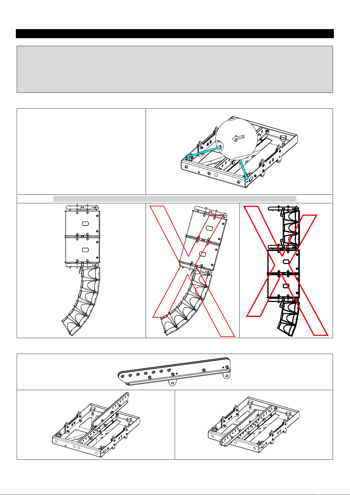
MSUB12 RIGGING
MSUB12-I Page 9 / 20
MSUB12 RIGGING
Place MSUB12 on the top of a second MSUB12.
Insert 4 pins (2 on both sides), provided with MSUB12-I.
Secure with the provided plates and the screws.

MSUB12 CABLING
Page 10 / 20 MSUB12-I
MSUB12 CABLING
MSUB12-I is packaged with the connection plate on the back. You can place a connection plate on the front.
Remove the connection plate with the cable glands. Place the
provided plate.
Remove the cable glands.
Assemble the cable glands on the front plate
Place the front plate on the grille. Pass the cable before closing
the front grille. The cable must pass through the lower left vent.

MSUB12 CABLING
MSUB12-I Page 11 / 20
How to connect a second cable?
Remove the driver.
Wire the provided connector WAGO 4pt.
Plug it to the free connector.
Pass the cable through the cable-gland.
Tight the cable-gland.
Close MSUB12.
MSUB12 - ACCESSORIES
Page 12 / 20 MSUB12-I
MSUB12 - ACCESSORIES
WARNINGS
All MSUB12 accessories are specifically rated in agreement with structural computations.
Never use other accessories –including push-pins –when assembling MSUB12 cabinets than the ones provided by NEXO:
NEXO will decline responsibility over the entire MSUB12 accessory range if any component is purchased from different
supplier.
All MSUB12 accessories have been designed so that cabinet are arrayed vertically.
VNT-BUMPM6
Rated for a maximum of 12 GEOM6 or 8 MSUB12,
or a combination with a maximum of 4 MSUB12 and
6 GEOM6.
Flown on 1 or 2 rigging points.
Usable with VNT-EXBARM6 for extra tilt angle and
flown on one or two rigging points.
1 location for laser/clinometer
Use VXT-BL615 or VNI-FIXBUMPM6 with MSUB12.
Use VXT-BL515 or GMI-BNFIX with GEOM6.
NO TILT –MSUB18 MUST ALWAYS BE POSITIONNED STRAIGHT AND ON THE TOP THE ARRAY
VNT-EXBARM6
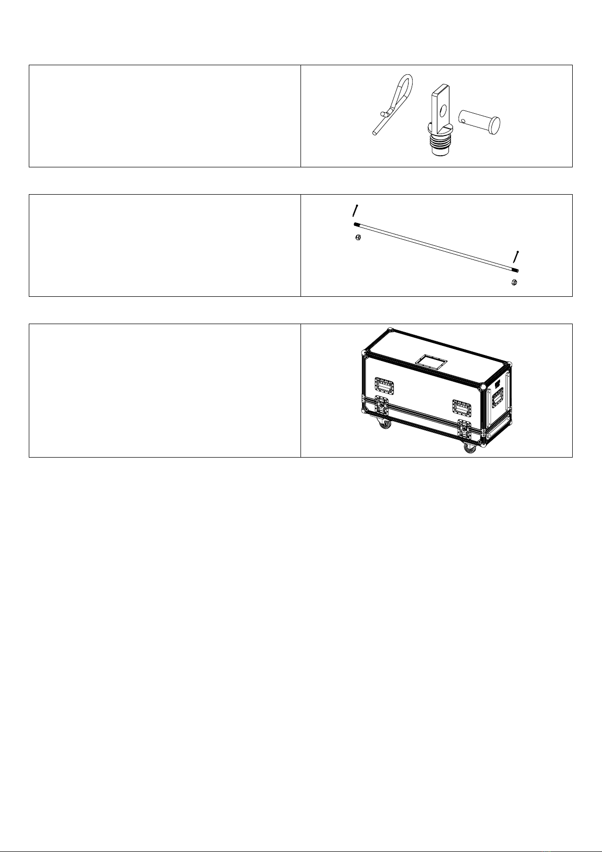
MSUB12 -ACCESSORIES
MSUB12-I Page 13 / 20
VNT-MNSTKM6
Stacking option for GEOM6 on top of MSUB12
(with GMT-BUMPER).
VNI-FIXBUMPM6
Fixing kit for VNT-BUMPM6 MSUB12.
MST-2CASEMSUB12
For 2xMSUB12 and VNT-BUMPM6 / VNT-EXBARM6

ARRAY EQ
Page 14 / 20 MSUB12-I
ARRAY EQ
The ArrayEQ allows to adjust the system frequency response in its lower range (see curves below, with different
ArrayEq values):

MAINTENANCE
MSUB12-I Page 15 / 20
MAINTENANCE
Grille changing
Remove 4 screws (Tx25).
Remove the grille.
12’’ Driver
Remove 8 screws (Tx25) to remove the Driver.
Remove the driver.
Red / Brown (+) / Black / Blue (-)

MAINTENANCE
Page 16 / 20 MSUB12-I
Spare parts
MARK
QUANTITY
REFERENCE
DESIGNATION
1
1
05DOUILM20
Connector Plate M20 Black (with screws)
1
05DOUILM20W
Connector Plate M20 White (with screws)
2
1
05MSUB12-UAI
Complete grille Installation Black (with fasteners)
1
05MSUB12-UAIPW
Complete grille Installation White (with fasteners)
3
4
05FTCC38x15
Pad 15/38 (x10)
4
1
05LEXSUB12I
Lexan MSUB12-I
1
05LEXSUB12I-PW
Lexan MSUB12-I White
5
1
05HPB12ND
1
05N12ND-4R/K
NOTE:
Speakers and Grills can be sent back to NEXO for recycling

TECHNICAL SPECIFICATIONS
MSUB12-I Page 17 / 20
TECHNICAL SPECIFICATIONS
MSUB12 WITH NEXO ELECTRONICS
Frequency range (±6dB)
55Hz 150Hz
Sensibility (1W / 1m)
102dB SPL Nominal
Peak SPL Level (1m)
130 dB
Operating voltage
35 Vrms
Crossover Frequency
55-85; 55-120; 55-150 Hz / 63-120; 63-150 Hz
Nominal Impedance
6
Recommended Amplification
450 to 700 W W
SPECIFICATIONS
Model
MSUB12
Components
1x 12 6 Ohms Long excursion Neodymium driver
Material
Baltic birch plywood
Finish
Black or white structural paint
Front finish
UV Resistant acoustic fabric fitted Magnelis® front grille
Fittings
2x Side handles
Stand fitting M20
Connectors
2 x cable gland, 2 cores cables
Weight
23 kg 51 lb
Dimensions

USER NOTES
Page 18 / 20 MSUB12-I
USER NOTES

USER NOTES
MSUB12-I Page 19 / 20

Other manuals for MSUB12 Series
1
This manual suits for next models
1
Table of contents
Other Nexo Speakers manuals


