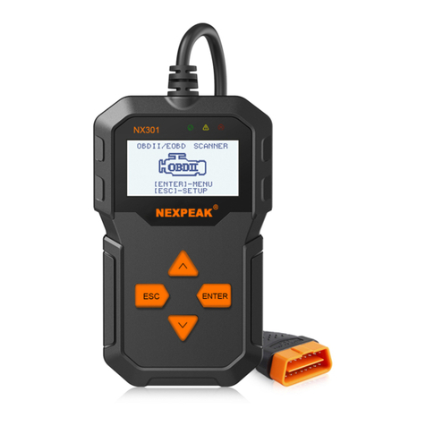
NEXPEAK NX301 User manual

N 301
X
CAN OBDII/EOBD
R
NEXPEAK
OBDII Scanner
N X 301


Table of Contents
1.Safety Precautions and Warnings
2.General Information
2.1 About NEXPEAK NX301
2.2 Specification
2.3 Package Accessories
3.Using the Scan Tool
3.1 Tool Description
3.2 Tool Language Setup
3.3 Vehicle Coverage
4.Tool Operation
4.1 Start Diagnostics
4.1.1
4.2 Read Codes
4.3 Erase Codes
4.4 Live Data
4.4.1 View Data
4.4.2 Record Data
4.4.3 Playback Data
4.5 View Freeze Frame Data
4.6 Retrieve I/M Readiness Status
4.7 Oxygen (O2) Sensor Monitor Test
4.8 On-Board Monitor Test
4.9 Component Test
4.10 View Vehicle Information
4.11 LED Interpretation
5.Print Diagnostic Report
6.Update The Scan Tool
7.Service Procedures
Connecting to Vehicle Power
4.1.2 Connecting to Personal Computer with USB Cable
EN
1
2
2
2
2
3
3
4
5
6
6
6
6
6
8
10
10
12
13
14
15
17
19
21
22
23
24
24
25

1.Safety Precautions and Warnings
To prevent personal injury or damage to vehicles and/or the scan
tool, read this instruction manual first and observe the following
safety precautions at a minimum whenever working on a vehicle:
•
• Wear safety eye protection that meets ANSI standards.
• Keep clothing, hair, hands, tools, test equipment, etc. away from
all moving or hot engine parts.
• Operate the vehicle in a well ventilated work area: Exhaust gases
are poisonous.
• Put blocks in front of the drive wheels and never leave the vehicle
unattended while running tests.
• Use extreme caution when working around the ignition coil,
distributor cap, ignition wires and spark plugs. These components
create hazardous voltages when the engine is running.
• Put the transmission in PARK (for automatic transmission) or
NEUTRAL (for manual transmission) and make sure the parking
brake is engaged.
• Keep a fire extinguisher suitable for gasoline/chemical/ electrical
fires nearby.
• Don't connect or disconnect any test equipment while the ignition
is on or the engine is running.
• Keep the scan tool dry, clean, free from oil/water or grease. Use a
mild detergent on a clean cloth to clean the outside of the scan tool,
when necessary.
Always perform automotive testing in a safe environment.
1

2.General Information
2.1 About NEXPEAK NX301
NEXPEAK NX301 Features the unique patented logical navigation
buttons, TFT backlit display screen and built-in speaker. The
NEXPEAK NX301 is the ultimate in ease and affordability, enabling
users to verify repairs, road test, check State, Emission Monitor
Status and solve engine systems and drive ability problems. The car
diagnostic functions of NX301is much more reliable and completely
superior to other model, it support full OBDII 10 Modes diagnostics.
Besides, with built-in Memory chip, allows users to print out stored
diagnostic data via PC, and life-time free update makes you no more
worry about your car malfunction in the future.
2.2 Specifications
1) Display: Back lit, 128 x 64 pixel display with contrast adjustment
2) Operating Temperature: 0 to 60^(32 to 140 F° )
3) Storage Temperature:-20 to 701 (-4 to 158 F° )
4) External Power: 8.0 to 18.0 V power provided via vehicle battery
5) Dimensions:
Length Width Height
127mm(5.00") 78mm(3.07") 20mm(0.79")
6) NW:0.23kg(0.501b), GW:0.31Kg(0.68 lb)
2.3 Package Accessories
1. User Manual - Instructions on tool operations
2. OBD2 cable - Provides power to tool and communicates between
tool and vehicle
3. USB cable - Used to upgrade the scan tool, and to print retrieved data
4. Protective Plush bag - A plush bag to store the tool when not in use
2

3.Using the Scan Tool
3.1 Tool Description
1) OBDII CONNECTOR - Connects the scan tool to the vehicle's
Data Link Connector (DLC)
2) LCD DISPLAY - Displays menus and test results
3) GREEN LED - Indicates that engine systems are running
4) YELLOW LED- Indicates there is a possible problem.
A "pending" DTC is present and/or some of the vehicle's emission
monitors have not run their diagnostic testing.
5) RED LED- Indicates there is a problem in one or more of the
Vehicle's systems. The red LED is also used to show that DTCs are
present. DTCs are shown on the Scan Tool's emission monitors have
not run their diagnostic testing.
6) ESC BUTTON - Returns to previous menu.
7) ENTER BUTTON - Confirms a selection (or action) from a menu list.
8) UP SCROLL BUTTON — Moves UP through menu and sub menu
items in menu mode. When more than one screen of data is retrieved,
moves UP through the current screen to next screens for additional data.
!
X
3
NEXPEAK
OBDII S canne r
N X 301

The scan tool allows you to make the following adjustments,
settings: 1) Select language: Selects desired language. Press
UP/DOWN key to Choose [Language] and press OK button, the
screen will display the interface as shown below:
9) DOWN SCROLL BUTTON — Moves down through menu and
sub menu items in menu mode. When more than one screen of data is
retrieved, moves down through the current screen to next screens for
additional data. It is also used as the language setup hot key when
pressed.
3.2 Tool Language Setup
Use the UP/DOWN and LEFT/RIGHT scroll button to Select
[System Setup] in the Main Menu and press OK, the screen will
display the interface as shown below:
5/6
Main Menu
Diagnostics
DTC Lookup
Review Data
Print Data
Tool Information
System Setup
1/6
Language
English
Français
Español
Deutsch
Pусский
Dutch
You can press UP/DOWN key to select any language and press OK
button to confirm. The system will convert to the chosen language
interface at once.
4

3.3 Vehicles Coverage
The scan tool is specially designed to work with all OBD II compliant
vehicle's including control area network (CAN), it is required by EPA
that all 1996 and newer vehicles (Cars and light trucks) sold in the
united states must be OBD II compliant. For European car makes,
after 2001 (gasoline engine) and 2003(diesel) should be correspond
with OBD II; For Asian car makes it should be after 2005 at least.
A small number of 1994 and 1995 model year gasoline vehicles are
OBDII compliant. To verify if a 1994 or 1995 vehicle is OBD II
compliant, check the vehicle emissions control information (VECI)
Label, which is located under the hood of engine or by the radiator of
most vehicles. If the vehicle is OBD II compliant, the label will
designate "OBD II Certified''. Additionally, Government regulations
mandate that all OBD II compliant vehicles must have a "common"
16 pins Data Link Connector (DLC)
VEHICLE EMISSION CONTROL INFORMATION
motor co. inc.
ENGINE FAMILY EFN2.8YBT2BA
DISPLACEMENT 2.8L
OBD II
CERTIFIED
THIS VEHICLE CONFORMS TO U.S. EPAAND STATE
OF CALIFORNIA REGULATIONS APPLICABLE TO
1997 MODEL YEAR NEW TLEV PASSENGER CARS.
REFER TO SERVICE MANUAL FOR ADDITIONAL INFORMATION
TUNE-UP CONDITIONS: NORMAL OPERATING ENGINE TEMPERATURE.
ACCESSORIES OFF,COOLING FAN OFF,TRANSMISSION IN NEUTRAL
EXHAUST EMISSIONS STANDARDS
CERTIFICATION
IN-USE
STANDARD CATEGORY
TLEV
TLEV INTERMEDIATE
SPARK PLUG
TYPE NGK BPRE-11
GAP:1.1mm CATALYST
EFN2.8YBT2BA
0 0 0 0 0 0 0 0 0 0 0 0
OBD II
CERTIFIED
For the vehicle to be OBD II compliant is must have a 16-pin DLC
(Data Link Connector) under the dash and the vehicle emission control
information label must state that the vehicle is OBD II compliant.
5

4. Tool Operation
4.1 Start Diagnostics
Before using the code reader, make sure to provide power to the code
reader.The unit operates on any of the following sources:
- 12-volt vehicle power
- USB connection to personal computer.
4.1.1 Connecting to Vehicle Power
The code reader normally powers on whenever it is connected to the
data link connector (DLC).
To connect to vehicle power:
1. Locate the data link connector (DLC). The DLC is generally
located under the dash on the driver side of the vehicle.
2. Connect the code reader with the DLC.
3. Switch the ignition key to the ON position.
4. The code reader automatically boots up.
4.1.2 Connecting to Personal Computer with USB Cable
The code reader also receives power through the USB port when it is
connected to a PC for updating software and transferring saved files.
To connect to PC:
1. Insert the small end of the USB cable to the USB port at the right
side of the code reader and the large end to a computer.
2. Press the power switch of the code reader to power it on.
4.2 Read Codes
Read Codes menu lets you read stored codes, pending codes and
permanent codes found in the control unit. Typical menu options
include:
Stored Codes: Diagnostic trouble codes stored in a control module
are used to help identify the cause of a trouble or troubles with a
vehicle. These codes have occurred a specific number of times and
indicate a problem that requires repair.
•
6

7
• Pending Codes: Pending codes are referred to as maturing codes
that indicate intermittent faults. If the fault does not occur within a
certain number of drive cycles (depending on vehicle), the code clears
from memory. If a fault occurs a specific number of times, the code
matures into a DTC and the MIL illuminates or blinks.
To read codes from vehicle:
1) Use UP/DOWN scroll button to select Read Codes from
Diagnostic Menu and press ENTER button.
2) Use UP/DOWN scroll button to select Stored Codes or Pending
Codes form the Trouble Codes menu and press ENTER button.
1/11
Diagnostic Menu
Read Codes
Erase Codes
Live Data
View Freeze Frame
I/M Readiness
O2 Monitor Test
1/2
Trouble Codes
Srored Codes
Pending Codes
• If there are no Diagnostic Trouble Codes present, the display
indicates "No (pending) codes are stored in the module!" Wait a few
seconds or press any key to return to Diagnostic Menu.
3) View DTCs and their definitions on screen.

8
P0118
S09
Generic
1/5
Engine Coolant Temperature
Sensor 1 Circuit High
Note: If no DTCs are present, the message "No (Pending) Codes
Found!" is displayed. If any manufacturer specific or enhanced
codes detected, NX301 reads the correct DTC information
automatically according to the VIN.
4.3 Erase Codes
CAUTION:
1.To clear codes, make sure that the ignition key is switched to ON
with the engine off.
2. Erase codes does not fix the problem that caused the fault! DTCs
should only be erased after correcting the condition(s) that caused
them by a technician.
To clear codes:
1) Use UP/DOWN scroll buttons to select Erase Codes from
Diagnostics Menu and press ENTER button.
2/11
Diagnostic Menu
Read Codes
Live Data
View Freeze Frame
I/M Readiness
O2 Monitor Test
Erase Codes

9
2) A warning message comes up asking for your confirmation.
Erase Codes
Erase trouble codes!
Are you Sure?
YES NO
3) Press ENTER button to confirm.
If the codes are cleared successfully, an "Erase Done!" confirmation
message shows on the display.
•
Erase Codes
Erase Done!
Press any key to con.
• If the codes are not cleared, then an "Erase Failure. Turn Key on
with Engine off!" message appears.
Erase Codes
Erase Failure
Turn Key on with
Engine Off!
Press any key to con.
4) Press any button to return to Diagnostic Menu

10
4.4 Live Data
4.4.1 View Data
The View Data function allows viewing of live or real time PID data
of vehicle's computer module(S).
1) To view live data, use UP/DOWN scroll button to select Live
Data from Diagnostic Menu and press ENTER button.
3/11
Diagnostic Menu
Read Codes
Erase Codes
View Freeze Frame
I/M Readiness
O2 Monitor Test
Live Data
2) Wait a few seconds while the scan tool validates the PID MAP.
Live Data
Reading PID.01
-Please Wait-
3) Use UP/DOWN scroll button to select View Data from Live Data
menu and press ENTER button.
1/3
Live Data
View Data
Record Data
Playback Data

11
Viewing Complete Data Set
4) To view complete set of data, use UP/DOWN scroll button to select
Complete Data Set from View Data menu and press ENTER button.
5) View live PIDs on the screen. Use UP/DOWN scroll button for
more PIDs if an UP or DOWN arrow appears on the screen.
1/84
Live Data
DTC_CNT 0
DTCFRZF P0000
FUEL SYS1 CL
FUEL SYS2 CL
LOAD_PCT(%) 0.0
ECT( F) 417
。
* The number "x" to the right of the screen indicates sequence of
highlighted item.
* If you want to view full name of the highlighted PID, press Help
button.
If the icon appears when a PID is highlighted, it indicates graphic
information is available. Press ENTER to view graph.
*
RPM(/min) 975
1725
925
6) Press ESC button to return to previous menu.
* You are allowed to pick up a maximum of 18 PIDs, if the selected
PIDs exceed 18, a "The selected data list is full!" message displays
on the screen.

12
4.4.2 Record Data
The Record Data function allows recording vehicle modules'
Parameter Identification (FID) data to help diagnose intermittent
vehicle problems. A recording includes 5 frames of live data before
trigger event and several frames after trigger event.
There are two trigger modes used to record data:
A. Manual Trigger - allows user to press ENTER button to start
recording.
B. DTC Trigger - automatically records PID data when a fault that
causes a DTC to set is detected by vehicle.
:
CAUTON DO NOT try to drive and operate the scan tool at the same
time! Always have another person operate the scan tool while driving.
2/3
Live Data
View Data
Playback Data
Record Data
The scan tool keeps recording PID data until user presses ESC button,
selected memory location is full, or it completes recording. A message
prompting to playback data shows on the screen.
Record Data
Record Done!
Playback data?
YES NO

13
4.4.3 Playback Data
The Playback Data function allows viewing of previously stored PID data.
1) To playback recorded data, use UP/DOWN scroll button to select
Playback Data from Live Data menu and press RNTER button.
3/3
Live Data
View Data
Record Data
Playback Data
You are also allowed to playback recorded data immediately after
recording.
2) Use UP/DOWN button to select the memory location marked
with an asterisk (*) icon.
1/6
Review Data
Location #1
Location #2
Location #3
Location #4
Location #5
Location #6
If there is no recording in selected location, a message "Not
Supported or Stored No Data" displays on the screen.
For data stored in temporary cache, you do not have to select
memory location.
3) Use UP/DOWN button to view recorded PIDs of each frame.
Use ENTER to convert pages or rows.
•
•
1/312
Playback Data
DTC CNT 2_
FUELSYS1 CL
FUELSYS2 CL
LOAD_PCT(%) 0.0
SHRTFT1(%) 48.4
DTC_CNT 2

14
The number "x/x" to the upper right comer of the screen indicates
total number of recorded frames and sequence of frame being displayed.
Negative frames indicate data recorded prior to trigger event, and
positive frames indicate data recorded after trigger event.
4.5 View Freeze Frame Data
1) To view freeze frame data, use UP/DOWN scroll button to select
View Freeze Frame from Diagnostic Menu and press ENTER button.
•
•
4/11
Diagnostic Menu
Read Codes
Erase Codes
Live Data
I/M Readiness
O2 Monitor Test
View Freeze Frame
2) Wait a few seconds while the scan tool validates the PID MAP.
View Freeze Frame
Reading PID.01
-Please Wait-
3) If retrieved in formation covers more than open screen, then a
down arrow will appear. Use DOWN scroll button, as necessary,
until all the data have been shown up.
1/8
View Freeze Fram
DTCFRZF B0090
LOAD_PCT(%) 0.0
ETC( F) 417
NAP(inH9) 76.2
RPM(/min) 12210
VSS(mph) 157

15
• If there is no freeze frame data available, an advisory message "No
freeze frame data stored!" shows on the display.
4) If you want to view full name of a PID, use UP/DOWN scroll
button to select the PID, and press HELP button.
ECT
Engine Coolant
Temperaturee
5) Wait a few seconds of press any button to return to previous screen.
4.6 Retrieve I/M Readiness Status
I/M Readiness function is used to check the operations of the
Emission System on OBD2 compliant vehicles. It is an excellent
function to use prior to having a vehicle inspected for compliance to
a state emissions program.
Some latest vehicle models may support two types of I/M Readiness
tests:
A. DTCs Cleared - indicates status of the monitors since the DTCs
are erased.
B. This Drive Cycle — indicates status of monitors since the
beginning of the current drive cycle.
An I/M Readiness Status result of "NO" does not necessarily indicate
that the vehicle being tested will fail the state I/M inspection. For some
states, one or more such monitors may be allowed to be "Not Ready"
to pass the emissions inspection.
"OK" —— Indicates that a particular monitor being checked has
completed its diagnostic testing.
"INC" — Indicates that a particular monitor being checked has not
completed its diagnostic testing.
"N/A" ——The monitor is not supported on that vehicle. 1) Use
UP/DOWN scroll button to select I/M Readiness from Diagnostic
Menu and press ENTER button.

16
1/2
I/M Readiness
Since DTCs Cleared
This Drive Cycle
5/11
Diagnostic Menu
Read Codes
Erase Codes
View Freeze Frame
O2 Monitor Test
Live Data
I/M Readiness
2) If the vehicle supports both types of tests, then both types will be
shown on the screen for selection.
3) Use UP/DOWN scroll button, as necessary, to view the status of
the MIL light ("ON" or "OFF") and the following monitors:
Misfire monitor — Misfire monitor
Fuel System Mon — Fuel System Monitor
Comp. Component — Comprehensive Components Monitor
EGR — EGR System Monitor
Oxygen Sens Mon — 02 Sensors Monitor
Catalyst Mon — Catalyst Monitor
EVAP System Mon — Evaporative System Monitor
Oxygen Sen htr — Oxygen Sensor Heater Monitor
Sec Air System — Secondary Air Monitor
Htd Catalyst — Heated Catalyst Monitor
A/C Refrig Mon — A/C system Monitor 4) Press ESC button to
return to Diagnostic Menu.
•
•
•
•
•
•
•
•
•
•
•

17
4.7 Oxygen(O2) Sensor Monitor Test
OBD2 regulations set by SAE require that relevant vehicles monitor
and test the oxygen (O2) sensors to identify problems related to fuel
efficiency and vehicle emissions. These tests are not on-demand tests
and they are done automatically when engine operating conditions are
within specified limits. These test results are saved in the on-board
computer's memory.
The O2 Monitor Test function allows retrieval and viewing of O2
sensor monitor test results for the most recently performed tests from
the vehicle's on-board computer.
The O2 Monitor Test function is not supported by vehicles which
communicate using a controller area network (CAN), For O2
Monitor Test results of CAN-equipped vehicles, see chapter
"On-Board Mon. Test".
1) Use UP/DOWN scroll button to select O2 Monitor Test from
Diagnostic Menu and press ENTER button.
6/11
Diagnostic Menu
Read Codes
Erase Codes
View Freeze Frame
I/M Readiness
Live Data
O2 Monitor Test
2) Wait a few seconds while the scan tool validates the PID MAP.
O2 Monitor Test
Reading PID...
-Please Wait-
Other manuals for NX301
1
Table of contents
Other NEXPEAK Scanner manuals
