Next 400 DPI User manual

-'
•
I
I
•
SERVICE
MANUAL
.
MAR.
1988

•
•
•
PREFACE
This Service Manual contains basic
info
rmation required
for
after-sales service
of
the
LBP-UX laser
beam
pnnter
. This
information
is vital
to
the
serviceman
1n
ma1ntaming
the
h1gh
printmg
quality
and per-
fo
rmance
of
the
pnnte
r.
This manual
is
made
based on
the
OEM standard manual.
Th1s
manual
consists
of
the
following
chapters:
Chapter 1: General DesGr
ipton
Features. specifications. and
operation
Chapter
2: Operation and
Timing
A
description
of
the
principles
of
operation
of
the
electrical and mechanical systems.
the1r
functions. and
timing
of
operations
Chapter 3:
The
Mechan1cal
System
Explanation
of
mechanical operation. disassembly. reassembly. and
adjustment
procedures
Chapter 4: Installation
ReqUirements
for
a suitable
location
and insta
llat
ion procedures. plus storage and handling
of
EP-S
cartridges
Chapter
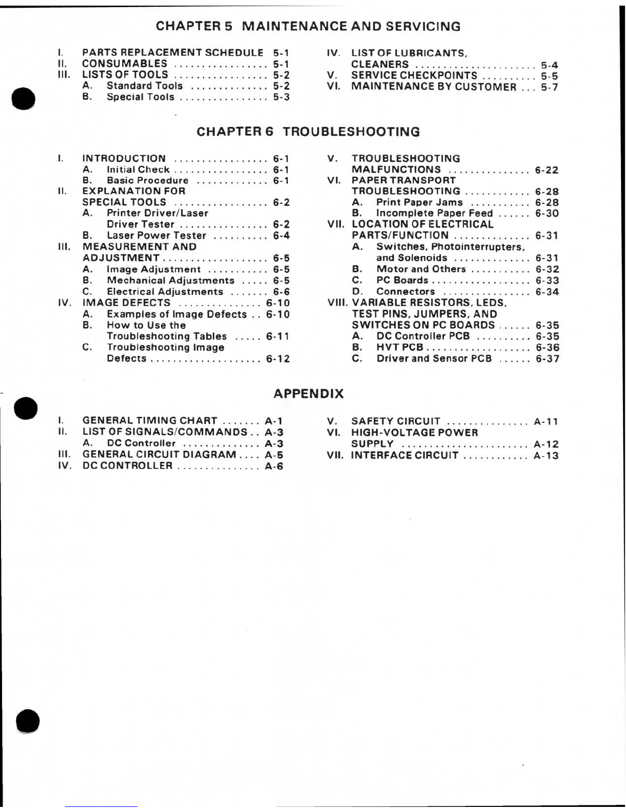
5: Maintenance and Servicing
Parts
replacement
schedule. tools. lubricants. and solvents
Chapter
6:
Troubleshooting
Reference values and adjustments;
troubleshooting
procedures
Appendix
:
Gen
eral
timing
chart. general
circuit
diagram.
PC
B ci
rcuit
diagrams. etc.

•
•
•
CONTENTS
CHAPTER 1 GENERAL DESCRIPTION
I.
FEATU
.RES
......................
1-1 IV.
PARTS
OF THE PRINTER
..........
1-5
II.
SPECIFICATIONS
.............
.
..
1-2 V.
OPERATION
..................
..
. 1-7
Ill.
SAFETY
INFORMATION
..........
1-4
CHAPTER 2 OPERATION
AND
TIMING
I.
BASIC
OPERATION
...............
2-1
Ill
.
IMAGE
FORMATION
SYSTEM
2-14
A.
Functions
. .
.................
2-1 A.
Introduction
. . . . . . . . . . . . . . . .
2-14
B.
Outline
of
the
Electrical
B.
Printing
Process
. . . . . . . . . . . . 2-19
System
...................
. . 2-2 C.
Operation
.
.........
.
.......
2-21
C.
DC
Controller
Input
D.
High-Voltage
Power
Signals
. .
..
.
.................
2-3
Supply
...
.
.............
...
.
2-23
D. DC
Controller
Output
IV
.
PICK-UP
/FEED
SYSTEM
........
.
2-23
Signals
......................
2-4
A.
Outline
.................
.
..
2-
23
E.
Basic
Sequence
of
B.
Cassette
/
Manual
Feed
.....
. 2-
24
Operations
....
.
..
.
......
.
...
2-6
C.
Fixing
Roller
Heater
II.
LASER
/
SCANNER
.............
.
..
2-8
Controller
.....
.............
2-25
A.
Laser
System
.............
.
..
2-8 D.
Paper
Jam
Detection
........
2-27
B.
Scanner
Drive
...........
.
..
2-12
V.
POWER
SUPPLIES
..............
2-28
A.
Outline
....................
2-
28
B.
Protective
System
. .
........
2-
28
CHAPTER
3
THE
MECHANICAL
SYSTEM
I.
II.
Ill.
IV
.
V.
EXTERNALS
.....................
3-1
A.
Covers
and
Panels
. . . . . . . . . . . 3-1
B. Fan
..........
.
..............
3-3
C.
Ozone
Filter
.................
3-3
D. AC
Controller
Unit
......
.
....
3·4
DRIVE
SYSTEM
..................
3-6
A.
Main
Motor
Unit
.............
3-6
PAPER
TRANSPORT
SYSTEM
..
.
..
3-7
A.
Pick-Up
Roller
Unit
.....
.
.....
3-7
B.
Feed
Guide
Unit
. . . . . . . . . . . . 3-1 0
EXPOSURE
SYSTEM
.........
...
3-11
A.
Laser
and
Scanner
Unit
......
3-11
ELECTROSTATIC
IMAGE
/
DEVELOPING
/
CLEANING
SYSTEM
.......................
3-14
A.
EP
-S
Cartridge
....
.
........
.
3-14
B.
Transfer
Corona
Unit
........
3-15
VI.
FIXING
SYSTEM
...
. . .
..
........
3-17
A.
Fixing
Unit
.................
3-17
VII.
ELECTRICAL
COMPONENTS
.....
3-
20
A. DC
Contro
ll
er
PCB
...
.
..
.
...
3-20
B.
Driver
and
Sensor
PCB and
Low-Voltage
Power
Supply
(Sensor/Power
Supply
Unit)
. 3-
20
C.
High-Voltage
Power
Supply
. . 3-21
D.
Signal
Ground
PCB (HVT)
....
3
-2
2
E.
Cassette
Si
ze
Sensing
Switch
PCB
................
3-
22
CHAPTER
4
INSTALLATION
I.
CHOOSING
A
LOCATION
....
...
..
4-1
II.
UNPACKING
AND
INSTALLATION
.
4-2
Ill.
STORAGE
AND
HANDLING
OF
EP
-S
CARTRIDGES
..........
.
..
. .
4-5
A.
Storage
of
Sealed
EP-S
Cartridges
..............
4-5
B.
Storage
of
Unsealed
EP-S
Cartridges
..............
4-5
C.
Handling
Suggestions
........
4·5

CHAPTER
5
MAINTENANCE
AND
SERVICING
I.
PARTS
REPLACEMENT
SCHEDULE
5-1
IV
.
LIST
OF
LUBRICANTS
,
II.
CONSUMABLES
.....
...
.....
...
. 5-1
CLEANERS
........
.
..
.
..
. .
......
5-4
Ill.
LISTS OF
TOOLS
.................
5-2 V. SERVICE
CHECKPOINTS
...
.
..
.
...
5-5
•
VI.
MAINTENANCE
BY
CUSTOMER
...
5-7
A. St
andard
Tools
........
.
.....
5-2
B.
Spec
ial
Tools
................
5-3
CHAPTER
6
TROUBLESHOOTING
I.
INTRODUCTION
.....
............
6-1 V.
TROUBLESHOOTING
A. Initial Che
ck
.......
...
. .
.....
6-1
MALFUNCTIONS
.......
.
.......
6-
22
B.
Basic
Proc
e
dure
.............
6-1
VI.
PAPER
TRANSPORT
II.
EXPLANAT
I
ON
FOR
TROUBLESHOOTING
...........
. 6-
28
SPECIAL
TOOLS
.
................
6-2 A.
Print
Paper
Jams
......
.
....
6-
28
A.
Printer
Dr
i
ver
/
Laser
B.
Incomplete
Paper Feed
......
6-
30
Driver
Tester
.....
.
..........
6-2
VII
.
LOCATION
OF ELECTRICAL
B.
La
s
er
Po
w
er
Te
ster
......
.
..
. 6-4 PARTS/
FUNCT
I
ON
..............
6-31
Ill.
MEASUREMENT
AND
A.
Switches
,
Photointerrupters
.
ADJUSTMENT
..
.
...
.
.....
. .
.....
6-5 and
Solenoids
............
. . 6-
31
A.
Image
Adjustment
..
....
. . . . . 6-5 B.
Motor
and
Others
...........
6-
32
B.
Mechani
cal
Adjustments
.....
6-5 C.
PC
Boards
..................
6-
33
C. Elec
trical
Adjustments
. .
.....
6-6 D.
Connector
s
................
6-
34
IV
.
IMAGE
DEFECTS
...............
6-10
V
III.
VARIABLE
RESISTORS. LEOS.
A. E
xa
mple
s
of
Image
Defects
. .
6-10
TEST
PINS
.
JUMPERS
,
AND
B.
How
to
Use
t
he
SWITCHES
ON
PC
BOARDS
......
6-
35
Tro
uble
sho
ot
i
ng
Table
s
.....
6-11 A. DC Co
ntro
ll
er
PCB
.........•
6-
35
C.
Troubleshoot
i
ng
Image
B.
HVT
PCB
.......
.
...........
6-36
Defe
ct s . . . . . . . . . . . . . . . . . . . .
6-1
2 C.
Dr
i
ver
and
Sensor
PCB
......
6-
37
•
APPENDIX
I.
GENERAL
TIMING
CHART
.......
A-1
V.
SAFETY
CIRCUIT
...............
A-11
II.
LIST
OF
SIGNALS
/
COMMANDS
..
A-3 VI.
HIGH
-
VOLTAGE
POWER
A. DC
Controller
.....
. . .
......
A-3
SUPPLY
..................
.
....
A-12
Ill.
GENERAL
CIRCUIT
DIAGRAM
....
A-5
VII
.
INTERFACE
CIRCUIT
.
...........
A-
13
IV
. DC CONTROLLER
.............
..
A-6
•

• CHAPTER 1
GENERAL DESCRIPTION
•
• I. FEATURES . .'
....................
1-1
IV
. PARTS OF THE PRINTER
..........
1-5
II. SPECIFICATIONS
................
1-2 V. OPERATION
.....................
1-7
Ill
. SAFETY
INFORMATION
.......
.
..
1-4

•
•
•
I.
FEATURES
1.
2.
3.
4.
5.
6.
7.
8.
This
high-speed.
non-impact
(low-noise)
printer
is based
on
electrophotographic.
electronic.
and
laser
technology.
The
pr
i
nter
produces
high-quality
pr
i
nts
on
plain paper. and can
produce
a large
variety
of
charac-
ters and
graphics
.
The
pnnter
is
compact
and easy
to
carry.
This
makes
it
easy
to
move
the
printer
to
where
it
1s
needed
.
A
corona
unit.
developing
cylinder.
photosensitive
drum
. and
drum
cleaning
unit
are
combined
int
o
a
single
assembly
called an "EP-S
cartridge
" .
The
cartridge
can be replaced
by
the
customer
when
necessary
. High
printing
quality
is
maintained
by
a
simple
cleaning
procedure
.
The
printer
can be
opened
and
closed
with
a
simple
one-hand
action
,
so
any
pape
r
jams
can be
cleared
easily.
Laser
beam
safety
is
designed
i
nto
the
pr
int
er
.
The
printer
is
approved
by
the
U.S.
Center
for
De-
vices
and
Radiological
Health (CD
RH)
.
The
power
supply
of
the
printer
will
operate
on
all
the
following
voltages
: 1
OOV
/
115V
/
220V
/
240V
(
50
/
60
Hz
).
The
scanning
pitch
(300
or
400
DPI) is selected and
the
printer
switched
ON
/
OFF
by
the
external
device
that
is
controlling
it.
1-1

•
•
•
II.
SPECIFICATIONS
1 Type
2.
Printing
method
3.
Printing speed
Cassette feed
4.
Time
for
first
print
5.
Warm-up
(WAIT)
time
6.
Opt
ical system
Laser
Scannmg
system
Scannmg p1tch
Honzontal
Vert1cal
7. Printing
system
Photosensitive
drum
Chargmg
Exposure
method
Development
Paper feed
Image
transfer
Separation
Fixing
method
Toner
supp
ly
8. Paper
Cassette feed
Manual feed
9 Cassette
1
0. Print delivery
1-2
Desk-top
page printer
Electrophotography
(
single-component
dry
toner)
8.1
prints
/min
(
A4
/Letter size)
~ge
l
I
I
1
OOV
/
115V
220V
i
240V
n
300
DPI
I
30s
or
less
25s
or
less
400
DPI
I
32s
or
less
I
27s
or
le
ss
Table
1-1
Note
: This table delineates
the
allowable time
from
when
a
Sig-
nal is received
by
the
printer
while
in READY
state
at
an
ambient
temperature
of
20
°C until
an
A4
or
Letter sized
sheet is printed and delivered.
2
min
or
less {af
ter
power
on until
the
printer
warms
up at
an
ambient
temperature
of
20°C)
Semiconductor
las
er
Rotating s1x-faced
prism
m1rror
300
or
400
dots
/in
300
or
400
rasters lines/in
OPC
Corona
Laser scanning system
Toner projection
development
system
Cassette {single cassettes; manual feed)
Corona-assisted
Tangential; (small
drum
radius/paper stiffness)
Heated roller
1
OOV
About
286W
115V
About
354W
220V
Abo
ut
962W
240V
About
11OOW
Included in replaceable EP-S
cart
ridge
Plain paper
of
A4
, Letter size
{60g
/m2-
80g
/m2paper)
Plain paper
from
1
OOmm x 1
75mm
to
216mm
x
356mm
(
60g
t
m2- 1
28g
im2paper)
A4
/Letter selection (De
pth
:
16mm-
about
150
sheets
of
80g
1m2
paper)
Face-up

•
•
•
11.
Print
tray
capacity
Plam
paper
:
12. Env1ronment
Temperature
Hum1dity
Atmospheric
13
. No1se level
14
D1mens1ons (W
X
D x Hl
15
. We1ght
16
.
Power
consump
t
ion
17. Line
voltage
requirements
About
50
sheets (8
0g
tm 2)
(
Number
of
sheets
depends
on
operatmg
env~ronment
.l
1
ooc
to
32
.5°C
(50°
F -91 °Fl
20
%
to
80
%
RH
570mmHg
to
760mmHg
(0m-2500m)
Under
50dB
(Al (PAINTING)
Under
45d8
(A) (
STANDBY
)
(1
m
away
from
the
pnnter
)
363mm
X
423mm
x
180mm
About
14kg
Max
.
540W
(1
OOV
.
pnntlng)
Max
.
640W
(11SV.
pnntmg)
Max
. 1
240W
(
220V
.
pnntmg)
Max
.
1390W
(
240V
. print1ng)
110111SV
(50
/
60Hz)
or
220/240V
(50
/
60Hz)
: selectable
with
a
switch
(Volt
age
tolerance
: ± 10%)
Spec
i
fications
are
subject
to
change
with
pr
oduct
imp
r
ovement
.
1-3

•
•
•
Ill. SAFETY INFORMATION
A. CORH
Regulat
io
ns
The
Cente
r
fo
r De
vices
and
Radiological
Health
(CD
RH
)
of
the U.S.
Food
and
Drug
Ad
-
mtntstration
1mplemented
regulations
fo
r laser
products
on
August
2.
1
976
.
These
regulations
apply
to
l
aser
products
manufactured
from
Allgust
1.
1976.
Comp-
liance
IS
mandato
ry
fo
r
pr
oducts
ma
rketed
in
the Un1ted
States
.
The
1nformat1on
shown
belo
w in
dicates
compliance
w1th
the
CDRH
regulation
s and
must
be
attached
to
l
aser
products
marketed
in
the
United
States
.
Note
:
This
pr
oduct
confo
rm
s
with
CD
RH
'
Rad
iation
Performance
Standard.
21
CFR
Cha
pter
1
Subchapter
J.
Manu
fac
tur
ed:
'-
------
--'
Figure
1-1
The
information
shown
above
is
subj
e
ct
to
change
depend
ing
on
the
pnnter
model.
1-4
B.
Addi
t
ional
In
fo
rmation
When
servicmg
or
adjustmg
the
opt1cal
sys-
tem
of
the
pnnter
. be
careful
not
to
place
sc
rewdri
ve
rs
or
othe
r
reflective
objects
in
the
pa
th
of
the
las
er
beam
.
Be sure
to
tak
e
off
accessories.
such
as
watches
and rings.
before
working
on
the
printer
. A
reflected
beam,
though
invis1ble.
can
permanently
damage
you
r eyes.
Since
the
beam
IS
tnv1sible. the
following
lab
el
is
attached
to
the
ms1des
of
covers
where
there
1s
danger
of
exposure
to
laser
radiation
.
DANGER-INVISIBLE
LASER
RADIATION
WHEN
OPEN
.
!.O
lD
DIRECT
EXPOSURE
TO
BEAM
.
I
VORSICH
-
'1SICHT8ARE
LASERSTRAHLUNG
.
.'
1EN
N
ABOECKUNG
GEOFFNET
UNO
SIC
HERHEITSVERRIEGEL
UNG
U
BERBRUCKT
NIGHT
OEM
STRAHL
AUSSETZEN
.
CAUTlON-I
NVISIBLE
LASER
RAOIAnON
WHEN
OPEN
.
AVOID
EXPOSURE
TO
BEAM.
I AnENTlON
-RAYONNEMENT
LASER
EN
CAS
D'
OUVERTURE
EXPOSITION
OANGEREUSE
AU
FAISCEAU
.
Figure
1-2

IV
.
PARTS
OF
THE
PRINTER
A. Ex
te
rnal Vi
ew
•
Fi
gure
1-3
•
Figure 1-4
•
(j)
Cassette
holder
®
Upper
unit
release
@
Upper
cover
@
Delivery
tray
®
Powe
r
cord
receptacle
®
Lower
cover
(j)
Interface
connector
®
EP-S car
tridge
®
Voltage
selector
®
Print
density
adjustment
dial
1-5

•
•
•
B.
Cross
Sectio
nal V
iew
1-6
I
f]l
CD
Laser/scanner
unit
\
\
I])
I
I
jJ
®
Preconditioning
exposure l
amps
@
Pri
mary
corona
unit
@
Mi
rror
®
Upper
cove
r
®
Pick-up
roller
(j)
Lower
cover
® Separati
on
pad
rr
~
'I>
I
I
ID
I
I
I
Figure 1-5
® Registration rollers
(j}
Transfer
corona
unit
©
Photosensit
i
ve
drum
@ Feed guide
@
Base
cover
@
Upper
fixing
roller
®
Lowe
r
fixing
roller
@ Delivery tray
I
J)

•
•
•
V. OPERATION
1.
Test
Print
button
The
test
print
button
is l
ocated
behind
a
panel
on
the
front
side
of
the
base
cover
. (See
Fi
gure
3-1
.)
Pressmg
1t
causes
the
printer
to
print
the
test
pattern
stored
in
the
memory
of
the
DC
controller
PCB.
After
the
printer
has
been
switched
ON
by
a
s
ignal
from
the external
device
and
the
ROY
sig-
nal has been
made
TRUE
by
the
printer
. pressing
the
button
will
cause
the
printer
to
print
a
page
of
the
test
pattern
.
If
the
button
is
held
down
.
the
pr
i
nter
will
pnnt
the
test
pattern
continuously
.
2.
Print
density
ad
just
ment
dial
The
pr
i
nt
density
adjustment
dial
can
be
seen
when
the
pr
i
nter
IS
opened
(See Figure
1-
4).
It
is used
to
adjust
the
print
density
.
Turning
the
dial
clockwise
lightens
the
print.
Normally
,
the
dial
should
be
set
to
the
" 5"
posit
i
on
.
ccw
(Da
rk
)
Figure
1-6
Dens1ty
1nd
ex
cw
(Li
ght)
1-7

•
-·
•
CHAPTER2
OPERATION
AND
TIMING
1.
This
chapter descr
ib
es
the
prin
te
r f
unc
tions. the relationships
bet
ween
mechan
i
sms
and circuits. and
timing
of
operations. Mechanical linka
ge
s are indicated
by
st
riped condUits ( • • • • )
,
control
sig-
nals
by
ar
rows
(
).
and grou
ps
of
signals
by
thick ar
rows
(
c:::::::)
).
2. The signals in dig1tal
circuits
are ident
ifie
d
as
"H"
for
H
IGH
an
d
"L"
for
LO
W.
The voltage
for
LOW
is
very close
to
OV
;
the
voltage
for
HIGH
dep
ends on
the
circuit.
If
a signal name has
no
bar
over
it
(e
.g.•
POP).
"H
" is a "
TRUE"
signal.
If
a signal name has a bar over
it
(e
.g..
Pi)l5),
"L"
is a
"T
RUE" signal. (A
"
TRUE"
signal
will
usually cause an
action
to
occur.
etc
.; a
"FALSE"
signal
will
normally prevent
the
operation).
I.
BASIC
OPERATION
...............
2-1
A.
Functions
........
.
...
.
.....
. 2-1
B.
Outline
of
the
Electrical
System
.....
. . .
.....
. . .
.....
2-2
C. DC
Controller
Input
Signals
......................
2-3
D. DC Co
ntroller
Output
Si
gnals
......................
2-4
E.
Basic
Sequence
of
Operat
i
ons
. . . . . . . . . . . . . . . . . . 2-6
II. LASER/
SCANNER
...
...
..........
2-8
A.
Laser
System
...............
. 2-8
B. Sc
anner
Dri
ve
. . . . . . . . . . . . . . 2-
12
Ill.
IMAGE
FORMAT
I
ON
SYSTEM
...
2-
14
A.
Introduc
t
ion
..
.
.............
2-
14
B. Pri
nting
Process
............
2-
19
C.
Operation
.
...............
. . 2-21
D. High-
Voltage
Power
Supp
ly
.....
.
...............
2-
23
IV
. PICK-
UP
/FEED
SYSTEM
.
........
2-
23
A. Outli
ne
....................
2-
23
B.
Casset
te/
Manual
Feed
......
2-
24
C.
Fixing
Roller
Heater
Controller
......
.
...........
2-
25
D.
Paper
Jam
Detection
........
2-27
V. POWER SUPPLIES
.......
.
......
2-
28
A.
Outline
....
.
..
.
............
2-
28
B.
Protect
i
ve
System
.
.........
2-
28

•
•
•
I.
BASIC
OPERATION
A. Functions
Printer
functions
can be di
vid
ed i
nto
five
groups
:
the
interface
system
.
the
overall
control
system
.
the
laser/scanner unit.
the
1mage
fo
r
mation
system.
and the
pape
r
pick-up
tfeed
system
.
.
To
external devi
ce
(
host
computer
)
~
-----n
____
_
______
___
,
: I
ln
~erfaca
PCB
I
I
NTERFACE
SYSTEM
1
L-----
~---
--
---
- -
---
-
_j
r
____
y
____
_
_________
,
I
I I
OVERALL
CONTROL
!
.
OC
contr
oller PCB .
SYSTEM
I
L
---~-----~--------~
__
SL__
~
--
-
-------
--,
I
LASE
R/
SCANNER
UN
IT
I I
MAGE
FORMATION
SYSTEM
1
1
1 I
I I
I
I
I
I
I
I
I
I
I
@]
!
.....---
......
I
L...;;.....;.;...........,~
I
I I
L _
______
_j
___
_
I
_____
j
I PAPER PICK..UP/
FEEO
SYSTEM
L------
-------------
----
-
~
Figure 2-1
Manual
feed
un•t
Cas
sette
2-1

•
•
•
B.
Outline
of
t
he
Elect
rical
System
Oper
ations
of
this
pnnter
are
controlled
by
two
microprocessors
on
the
DC
cont
ro
ll
er PCB.
When
the
printer
power
is
switch
ed ON
by
a signal
from
the
external
device.
the
microprocessors
output
s1gnals to
dnv
e
the
laser
diode.
scanner
motor.
mam
motor
, and
othe
r
components
in response
to
commands
and
im
age
da
ta
received
from
the
external
device
via
the
interface
PCB.
2-2
I
I
I
-:;
<:
I !
I
~
I
I
I
I
~
I
I
I
I
I
L
_-l
..
u
~
4icc
~~
~
I
I
I
I
!
I
l
I
l
'----
Optical
fiber
~
Laser
diode
Scanner
motor
DC High·voltage
contro
ll
er
PCB
unit
Cassette so
ze
sensing
switch
Driver/sensor
l PCB
Ma
in
motor
Saftty
PCB
l
Low-voltage
AC
controll
er
pow.r
supply
PCB 1
Figure
2-2
.I
Primary I
I
corona/grid
bias
J Transfer
corona
J
r--
1 I
t-----'
I
Dev~
·t>
oong
bias
~
I
J
Static
cnarge I
l
eliminator
Toner
sensor J
J Sensors/selenoids I
I
L
J
Precondit
oonong J
l
expo
sure
l
amps
•
I
Delivery
unit
paper
l
1
sensor/thermostor
J Rollers/pt1oto-
I
I sensotive
drum
~
Fixing
roller
heater
J

•
•
•
C.
DC
Co
ntroller
Input
Signals
Delivery un1t
paper
sensor
Thermistor
Paper sensor
~l~erPCB
J85
1-2 J206-2 I
r-
-+)-------.:....::...:....::..
...:..-<1
POP (H when
paper
Is
sensed)
·3
.J
~----~~--~--------~~
'--------
~
~-
·
..:..._
1
---~
·
.:._1
w+5V
~---
~
~~---
·
.:
5:..._
_____
·.::5
_1
FSRTH (Voltage
drops
as
f1x1ng
roller
~
r 4 4
temperature
roses
I
~
j+
Driver
and
sensor PCB
I
~~----~--~•>--J3_0_1_·7
________
J_21_3_·7
__
~
4
~~t+SV
PS301
.a
a I
(:::::)J.r--
-~;>---.:...----
--·.:...4,.
PEMP
(H
when cassette has paper)
.s I
tJ.
Manual feed un1t
paper
sensor
I
~
...-
---tl>---
·
.::
9
______
·
.::9--<~
MPFS (H
when
there
IS
no
pacer
on
manual feed
trav
l
~
I
Drum senSitiVtW
ident1ficat1on
switches
EP-S cartrodge
L
/
'\
TB701
.....
"'
I
i
1
Toner
sensor
·1 ·1
I
ffiNsi
l
SW30:
I
~-o--
o-----
-+).--
---·
2
___________
·
2
-~
CSENS2
SW301
(See page 2-101
HVT
unit
----,
HVT
PCB
I
I
I
I
~~-
J7
_o_,_
·5
--~~~-
J
_
7
_o2_
·
_5
__________
4
~
J2114
I
I
I
I
TENS (Falls below
a
threshold voltage when
toner
holder
IS
empty)
Scanntng
unit
= = O
=p=
ti
=c•:::,
'='=i
be='===fi
=======
J::2::0=1=,
~
80
L_
Figure
2-3
2-3

•
•
D.
DC
Controller
Output
Signals
Laser
diode
PCB
Laser
diode
I
L
Scanner motor
Reg1strat1on
roller cluten
soleno
id
2-4
-2
.J
.J -2
-1
LOAV
(H
to
swttch laser
ON)
PO (Voltage 1n propOrtiOn
to
tntensitv
of
laser
beaml
OSAOJ
r-----
~r_-
__
-
__
-_-
__
-_-
__
-
__
-
__
-
__
-~_J_
20
_
3
_.~
7
~+24VA
I
,.---r-----------'--.:.:
·
S~<i
SC
NCONT
(H
to
drtve s
canner
motor)
-----------~
r-
-
------
__
d--
1
;~
TG
I :
1
I
..__---
----
--~
.
..
rn
-3
REGO
(H
to
operate
regiStration roller)
Figure
2-4

•
Preconditionin
exposure
1 9
amps
•
•
Lamoboard
/
scanner
untt
h
----~
o~,ustng
Precondrttonrng
__
_
exposure
I
r - - -
!.m3
board
I
---.,
I
~
J801·2
i
!
\S)
-==·
~:!·:~
=--=-
---
'-
I
____
.J
Safety
PCB
Figure 2-5
r-=-
1
u~..
controller
PC
B (2/2)
PEXPO (
L
to
swrtcn
lamps
ON)
preconditronrng e
xposure
FAN
L
2-5

•
•
•
E.
Basic
Sequence
of
Operations
Two
consecutive
prints
on
A4
paper
165
°C
POWER
ON
PANT
o'o,),l f ;
..,.,
.,.
'
NM
U P
,
-
~
.
,., .
..
1. .
·•
j_
,·
o•
J-
i
'O
''
-I I I
I
--
I
ROY
signal
Fixing
roller
heater
165"C
I I I
1ao•c
I I I
Mai
n m
otor
IJi
.._About I
<ec
. j I 1 I I
Pri
mary
coron
a II
~
Aoout
0 .5
tee
. I I I
Transfer
corona
II
I
~About
1.3 sec. I I
II I I I
Scanner
motor
Laser
diode
About
l
<ec
.l
About
7 4 sec. --1
P
ick-
up
roll
er
AOOUI
1
<OC
.
~
I
clu
tch
solenoid
Registration
rol
l
er
About
6 .2 sec ..j
1--
clutch
solenoid
VE
RTICAL
SYNC
..j
~
Aoou
1 0.
02
sec
.-.IJ..
Abo~o~c
0.
02
sec.
signal
Figure
2-6
Per
iod
Purpose
WAIT
From POWER ON unttl
the
Fi
xing roller
warm-up
(
WAIT
period) fixing
ro
ller
tem
perature
reaches
165°C
.
(T
wo
mi
nutes
or less
man
1a
mbient
tem
perat
u
re
of
1
2o
•
c1
. I
STBY IFrom the end
of
th
e
WAIT
Fixi
ng
roller held
at
1
65
°C T
(STANDBY) peri
od
until: to keep
the
printer
ready
to
I1. a PRNT signal is
inputted
print
.
I
fro
m the external device.
or
I
2.
from
the end
of
the
LSTR3
per
i
od
until
a
PANT
si
gnal is i
nputted
from
the
externaldevice.
or
I
3.
the
power
is
switched
OFF.
WMUP
After
the
PANT signal has Fixing roller
warm-up
(
WARM
-UP period) been
inputted
from
the
external
dev
ice
until
the
fixing
roller reaches
175
•c .
(10 sec.
or
less.)
INTR For
about
2 sec.
after
th
e Residual charges removed
(INITIAL main
motor
starts
rotating
from
the
drum
and
its
ROTATIONS
for
pr
i
nt
ing.
photosensitivity
stabilized
per
iod) in preparation
for
printing.
Table
2-1
2-6
· ; - '
1ss•c
Remarks

Period
I
Purpose
I
Remarks
•
PAI
NT
I
For
about
17.9 sec.
from
The
VDO
sagnal
from
the
I
(Print)
paper
pi
ck-up
(about
20
.4
1
external device.
conveys
all
i sec.
for
legal
size).
1
ima
ge
data.
the
i
mage
as
I
I
'
fo
rmed
on
the
photosensatave
drum
. and .
I .
the
amage as
transfe
rred
to
paper
.
I
LSTR1 ' From
when
the
transfer
last
printed
page delivered.
Whenever
a PANT sagnal as
(FI
NAL
co
ro
na
goes
OFF
untal
the
l
•n
putted
from
the
external
ROTAT
IONS 1
pnmary
corona
goes
OFF. devace.
the
INITIAL
period) • ROT
ATIONS peraod beg
ans
I
!ammedaately.
LSTA2
From
when
the
primary
Last pranted page delivered.
I
If a PANT sign
al
is anputted
(FI
NAL
co
rona
goes
OFF
unt
il
the
from
the
external devace.
ROTATIONS 2 d
evelop
ing
baas
(DC) goes
the
developang bi
as
(DCI
penod
)
OFF
.
I
goes
OFF
. then
the
INITIAL
I
ROTATIONS
penod
begans.
LSTR3 From
when
the
developing
Last
printed
page
del
ivered. I tt a PANT signal is
inputted
(FINAL bias (DC) goes
OFF
until
the
t
from
the
external
dev
ac
e.
ROTATIONS 3
mam
motor
stops
.
1
the
INITIALROT
ATIONS
period)
I
period begans ammedaately
Table 2-2
•
•
2-7