Nextek PVT-HH User manual
This specification is for reference only and is subject to change without notice.
©2023Copyright, All Rights Reserved
101 Billerica Ave., Building 5, Suite 101
North Billerica, MA 01862
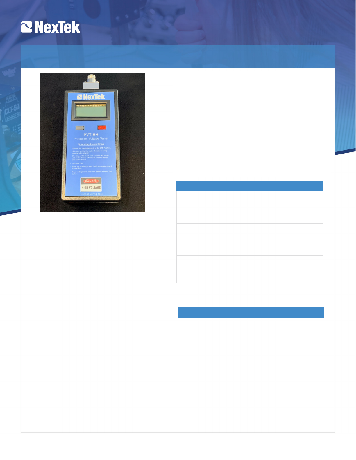
Protection Voltage Tester, PVT-HH
Mechanical Specifications
Size
7.3” x 3.25” x 1.25”
Weight
14 ounces
Power
Two (2) 9V Batteries
Test Output
1KV min, 1 mA min, 1.5mA Max.
Display
2” LCD
Interface
N Female
Included in PVT-HH
Alligator Clip
Batteries
Storage Case
Embedded Features
•
Auto Shut-off - For battery management
purposes.
•Auto Disable of HV out if the test button is
engaged longer than10 seconds (engage test
button to reactivate)
•I/O switch and TEST button designed to resist
unintentional activation.
•Fast discharge time between tests.
•
PVT-HH
Protection Voltage Tester, HH unit
, with Type
N Female Interface, Alligator Clip Assembly
and Storage Case.
•
PVT-ADPKIT
Between Series N Male Adapters to TNC,
BNC & SMA Male / Female Interfaces
•
PVT-ACNM
Alligator Clip with N Male Connector
FEATURES:
•
Hand-Held Portable Device
•
Compact & Lightweight Design
•
Ability to test surge components utilizing
the Alligator Clip Assembly
•
Rugged Storage Case
APPLICATIONS:
•
Test Surge Protection Devices
•
Test Components: Diodes, Metal Oxide
Varistors [MOVs,] and Gas Discharge
Tubes [GDTs]
This Protector Voltage Tester [PVT] can check any surge
lightning device to confirm proper functionality in order
to protect your critical RF equipment from damage.
The PVT is a portable, light weight, hand-held battery
powered unit. The unit is designed with one Type N
female interface. However, it can also be supplied with
numerous between-series adapters (PVT-ADPKIT) or an
Alligator Clip (PVT-ACNM) to meet many of the popular
surge protection interfaces available.
The PVT-HH is also supplied complete with a storage case,
two 9-volt batteries, and operating instructions printed on
the unit

This specification is for reference only and is subject to change without notice.©2023Copyright, All Rights Reserved
101 Billerica Ave., Building 5, Suite 101
North Billerica, MA 01862
Protection Voltage Tester, PVT-HH
Notes:
Preparation:
Prior to using the PVT-HH, the batteries must be
installed. The PVT-HH is shipped with two
standard 9V batteries.
To install the batteries, remove the four back
cover screws and the back cover itself. Install
both 9V batteries and replace back cover and
screws. The PVT-HH is now ready to use.
Operation:
Testing of RF lightning protection devices is
simple and very straightforward. Prior to testing,
please read the “Warning to Users” section at
the beginning of this manual to understand the
potential hazards that may arise in operating the
PVT-HH inappropriately.
As described in the overview section, the PVT-
HH will test a broad variety of RF lightning
protection and discrete component level
devices. Prior to testing, the operator must
remove the device to be tested from the system
it protects. In the case of a RF lightning
protection device, connect the surge side end of
the RF lightning protection device onto one of
the type-N connector. Or, if testing a discrete LP
component such as a leaded GDT or MOV,
using the provided flying lead adapter or other
appropriate adapters and test leads, you may
connect the discrete LP component to the PVT-
HH.
To Use:
1. Ensure that the test meter is in the OFF state prior
connecting DUT to the tester.
2. Once the DUT is safely and securely connected to the PVT-
HH, press and hold the grey power button and wait for the
LCD to display “ON”.
3. Once the meter is in the “ON” state, press and hold the red
test button down to apply the test Voltage to the DUT for
approximately 10 seconds. The device’s DC break down
Voltage is displayed on the LCD.
4. Allow the voltage indicated on the display to stabilize. Then
observe the peak DC breakdown voltage.
5. Once testing is completed, release the test button. The
PVT-HH has a discharge feature that quickly discharges the
output to a safe level after the test button is released2. You
may then remove the DUT from the PVT-HH.
6. Upon completion of testing, press and hold the power
button until the LCD displays “OFF”, then release the
power button.
1) If testing multi-stage lightning protection devices, the PVT-HH will measure
the peak voltage of the device with the lowest breakdown voltage in the
configuration.
2) The PVT-HH possesses a safety feature that will quickly discharge the high
voltage present on the output connectors after the test button is released.
3) The PVT-HH will enter “sleep” mode after 10 minutes of inactivity.
4) As measured with a DC supply voltage (battery) of 18.0V +/-0.1V.
5) The output voltage of the PVT-HH is directly affected by the state-of-charge
(SoC) of the installed batteries. Although the PVT-HH will operate
accurately with batteries that have a low SoC, the maximum output voltage
will be lower than 1000V.
THE PVT-HH CAN PRODUCE VOLTAGES IN EXCESS OF 1000V. ALTHOUGH THE CURRENT SUPPLIED BY THE TESTER ITSELF IS LIMITED
TO A NON-LETHAL LEVEL, IT IS POSSIBLE THAT THE CAPACITANCE OF A DEVICE UNDER TEST CAN BE LARGE ENOUGH TO STORE A
DANGEROUS AMOUNT OF ELECTRICAL ENERGY THAT CAN DELIVER A DAMAGING OR EVEN FATAL SHOCK TO THE USER.
ACCIDENTAL CONTACT WITH THE TEST LEADS WHILE THE TESTER IS OPERATING CAN DELIVER A PAINFUL SHOCK, AND EVEN
THOUGH THIS IS UNLIKELY TO BE DIRECTLY INJURIOUS OR FATAL TO A HEALTHY PERSON, THE DRAWBACK REACTION TO THE DC
SHOCK MAY CAUSE THE USER TO BE INJURED BY STRIKING NEARBY OBJECTS THAT POSE A HAZARD. FOR THIS REASON, THE PVT-
HH MUST BE USED WITH CARE IN CONFINED SPACES AND SENSIBLE PRECAUTIONS OBSERVED DURING OPERATION TO PREVENT
INJURY.
NEXTEK CANNOT AND DOES NOT ASSUME RESPONSIBILITY FOR INJURY OR DEATH ARISING OUT OF THE USE OF THIS TESTER.
ELDERLY PERSONS AND THOSE WITH ANY INDICATION OF HEART PROBLEMS ARE STRONGLY DISCOURAGED FROM USING THIS
EQUIPMET. IT IS RECOMMENDED THAT THE LP-SPT BE USED ONLY BY EXPERIENCED PERSONNEL TRAINED IN ELECTRICAL SAFETY
PRACTICES. THE PROCEDURES OUTLINED IN THIS MANUAL SHOULD BE CAREFULLY FOLLOWED TO ASSURE SAFE OPERATION OF
THE TEST.
Doc No. 508-0153 R00
HIGH VOLTAGE HAZARD-WARNING TO USERS:

This specification is for reference only and is subject to change without notice.©2023Copyright, All Rights Reserved
101 Billerica Ave., Building 5, Suite 101
North Billerica, MA 01862
NexTek Surge Arrestor Series and Part
Numbers
Tester Port Side to
Coaxial Arrestor
Surge Arrestor
Technology Surge Direction
Min Voltage
Reading (Volts)
Max Voltage
Reading (Volts)
PTI-BB50 Series (1.5-1000 MHz, N Conns, DC Block, 2kW,
50kA, Hole Mount)
PTI-BB50NFF Surge Side; N-Female DC Block Directional 480 720
PTI-BB50NMP Surge Side; N-Female DC Block Directional 480 720
PTI-BB50NMS Surge Side; N-Male DC Block Directional 480 720
PTI-BB50 Weatherized Series (1.5-1000 MHz, N Conns, DC
Block, 2kW, 50kA, Hole Mount)
PTI-BB50NFF-W Surge Side; N-Female DC Block Directional 480 720
PTI-BB50NMP-W Surge Side; N-Female DC Block Directional 480 720
PTI-BB50NMS-W Surge Side; N-Male DC Block Directional 480 720
PTC S-Series (DC-3.2 GHz, 50kA, NF to NF; 0.630" dia.
Bulkhead Mount)
PTCONFONF09S Either Side DC Pass; GDT Bi-Directional 72 108
PTCONFONF23S Either Side DC Pass; GDT Bi-Directional 184 276
PTCONFONF35S Either Side DC Pass; GDT Bi-Directional 280 420
PTC E-Series (DC-6 GHz, 20kA, NF to NF; 0.630" dia.
Bulkhead Mount)
PTCONFONF09E Either Side DC Pass; GDT Bi-Directional 72 108
PTCONFONF23E Either Side DC Pass; GDT Bi-Directional 184 276
PTCONFONF35E Either Side DC Pass; GDT Bi-Directional 280 420
QSS 1 /4-Wave Short Series (820-2.2GHz, DC Block, 1 /4-
Wave Short, 60kA, 0.630" dia. Bulkhead Mount)
QSSNFNF0300 Either Side DC Short; 1 /4-Wave Bi-Directional 0 2
QSSNFNM0300 Either Side DC Short; 1 /4-Wave Bi-Directional 0 2
QSS 1 /4-Wave Short Series (2.4-6 GHz, DC Block, 1 /4-
Wave Short, 60kA, 0.630" dia. Bulkhead Mount)
QSSNFNF0400 Either Side DC Short; 1 /4-Wave Bi-Directional 0 2
QSSNFNM0400 Either Side DC Short; 1 /4-Wave Bi-Directional 0 2
FPL AP06 Series (400-2700MHz, N Connectors, 6V DC,
<4A, 25kA, DC Filtered)
FPLNFNFAP06 Either Side DC Pass; Hybrid GDT/Diode Directional 5 7
FPLNFNMAP06 Either Side DC Pass; Hybrid GDT/Diode Directional 5 7
FPLNMNFAP06 Either Side DC Pass; Hybrid GDT/Diode Directional 5 7
FPL GPS Series (1.1-1.7 GHz, 0.750" Dia Bulkhead Mount,
6V DC, <2.5A, DC Filtered; Best GPS Residuals)
FPLNFNFDP05 Either Side DC Pass; Hybrid GDT/Diode Directional 5 7
FPLTFTFDP05 Either Side DC Pass; Hybrid GDT/Diode Directional 5 7
Protection Voltage Tester, PVT-HH
Acceptable Voltage Limits


