Nexus 21 E-500 User manual

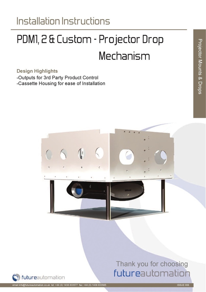
Projector Lift Model E-500
Installation Instructions

2
(Intentionally Left Blank)

3

4
Contact: Sup[email protected]
Toll Free: (866) 500-5438
Phone: (480) 951-6885
Fax: (480) 951-6879
Revised: 3/13/18
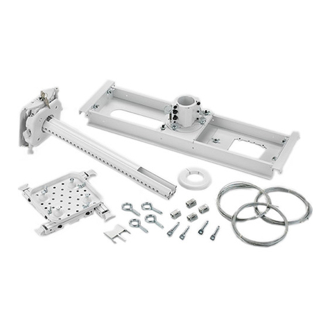
Below is a parts list describing all of the items included with the Model E-500 System. You may also wish to
refer to the dimensional diagram shown on pages 22-24.
Before beginning assembly and installation, please make sure that you have all items included on the list. If any
parts are missing or damaged, please contact Nexus 21 using the contact info shown at the top of this page.
Parts List
E-500 Lift Mechanism
Carrier Shroud
Universal Adjustment Bracket
Installation Bracket (Pre-Framed)
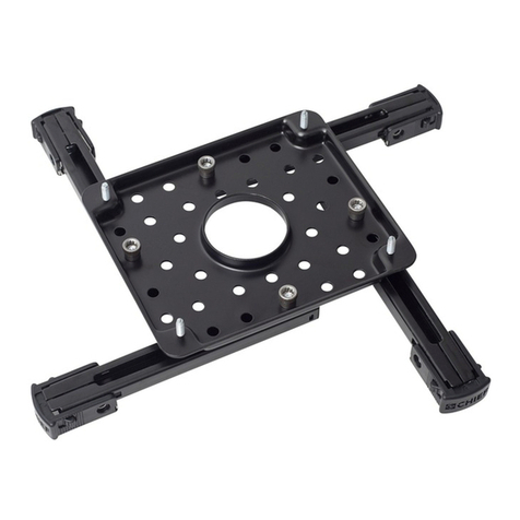
Interface Plate
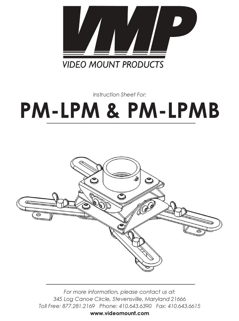
Universal Mounting Bracket

5
Parts List Continued
Hardware
1. Eight (8) -- 5 x 14mm FHMS (Flat Head Machine Screw)
2. Four (4) –Set Screws
3. Four (4) –Fine Adjustment Screws
4. Sixteen (16) -- #8 –½” FHWS (Flat Head Wood Screw)
5. One (1) –3mm T-Handle

6
SAFETY INFORMATION
SEVERE PERSONAL INJURY AND PROPERTY DAMAGE CAN RESULT FROM IMPROPER INSTALLATION OR ASSEMBLY.
READ THE FOLLOWING WARNINGS BEFORE BEGINNING:
WARNINGS:
1. Do not use this product for any application other than those specified by Nexus 21.
2. Do not exceed the weight capacity. This can result in serious personal injury or damage to the equipment. It is the installer’s
responsibility to ensure that the total combined weight of all attached components does not exceed that of the maximum figure stated.
3. Follow all technical specifications and instructions during the installation.
4. Only use attachments/accessories specified by the manufacturer.
5. Close supervision is necessary when this system is being used by, or near, children, or disabled persons.
6. It is the responsibility of the installer to warn all potential users of the dangers of interfering with the mechanism during operation.
7. Read all technical instructions fully before installation and use. It is the installer’s responsibility to ensure that all documentation is
passed on the users and read fully before operation.
8. Failure to provide adequate structural strengthening, prior to installation can result in serious personal injury or damage to the
equipment. It is the installer’s responsibility to ensure the structure to which the Lift System is affixed can support four times the weight
of the system.
9. Risk of electric shock. Do not attempt to open the Control Box.
10. To reduce risk of fire or electric shock, do not expose parts to rain or other liquids.
11. Protect the power cord from being walked on or pinched.
12. Keep all documentation.
13. Heed all warnings.
14. Clean only with a dry cloth.
15. Refer all service questions to Nexus 21 if the system does not operate normally.
Nexus 21 disclaims any liability for modifications, improper installations, or installations over the specified weight range. Nexus 21 will not be liable for any damages
arising out of the use of, or inability to use, Nexus 21 products. Nexus 21 bears no responsibility for incidental or consequential damages. This includes, but is not limited
to, any labor charges for the servicing of Nexus 21 products performed by anyone other than Nexus 21.
Nexus 21 intends to make this and all documentation as accurate as possible. However, Nexus 21 makes no claim that the information contained herein covers all
details, conditions or variations, nor does it provide for every possible contingency in connection with the installation or use of this product. The information contained
in this document is subject to change without prior notice or obligation of any kind. Nexus 21 makes no representation of warranty, expressed or implied, regarding the
information contained herein. Nexus 21 assumes no responsibility for accuracy, completeness or sufficiency of the information contained in this document.

7
Types of Controls for Nexus 21 Lift Systems
All Nexus 21 Systems come standard with a wireless remote control and receiver. We offer a choice of two different types of remotes:
IR and RF (both of which are explained in detail below). Our standard control type is RF, so unless you specifically requested the IR
version when you made your purchase, you probably received the RF controls with this Lift System. The method of installation for
each type of remote control is slightly different, so you should now identify which type of remote you have by reading below, and
then follow the instructions for that type of remote.
NOTE: If you will be using a system with a home control system (like the ones made by companies such as Crestron or Control 4) the
most common form of control is to WIRE IT DIRECTLY to the relays of your home control system. This direct-wire method is called
Integration by Contact Closure, and is accomplished by using the Contact Closure Hardware that is supplied with the IR Control Kit to
connect the Lift to your home control system.
Identifying the System Control Type
IR (Infrared) –This control option allows you to utilize a 3rd party universal style remote control to raise and lower the TV Lift.
Your universal remote will “learn” the IR codes from the provided IR Handset, which will enable you to control the lift. The universal
remote will then communicate with the “eye” located on the IR Receiver via your 3rd party emitter (or flasher). Instructions for
setting the travel limit for the system are on Page 21.
NOTE: If you are NOT planning on using a 3rd party Universal Remote, switch to the RF setup. (There is no charge for swapping)
These are the parts included with IR controls:
Contact Closure Hardware IR Receiver IR Handset Height Limit Insert
RF (Radio Frequency) - This system utilizes a wireless remote-control handset that sends a radio signal to the RF Receiver. The
radio signal can go through ceiling material and does not require line-of-sight. Instructions for setting the travel limit for the system
are on Page 21.
TIP: Planning to integrate the TV Lift with your UNIVERSAL REMOTE CONTROL? The RF version of the Nexus 21 controls won’t do it. Switch to IR.
These are the parts included with RF controls:
Backup Switch RF Receiver RF Handset Height Limit Insert
Integration by Contact Closure –To direct-wire the TV Lift controls to a home control system (Crestron, Control 4, AMX, etc.)
you will use the Contact Closure Hardware. You won’t use any Nexus 21 receiver or handset for this type of control because you will
use the handset or control pad that comes with your home control system. Instructions for setting up the System using Contact
Closure are on “Page 25”.

8
Safety & Reference Information
SAFETY NOTICE:
- For proper support, this System MUST NOT be attached to any material that is less than ¾” thick.
- This System is ONLY designed and rated for VERTICAL, NON-INVERTED USE. DO NOT MOUNT THIS LIFT SYSTEM
UPSIDE DOWN or SIDEWAYS (HORIZONTALLY)!
- This installation is to be completed by a licensed installer or contractor
- All electrical hookups must be installed per authorized building codes
.
All information provided below is located within the Model E-500-Dimensional-Drawing for more information
pertaining to the specifications listed below, refer to the dimensional drawing located at the end of this manual.
Dimensional Drawing PDF’s are available upon request.
All measurements are shown in inches with Centimeters shown inside [ ]
Minimum Framing Dimensions for the E-500 System are as follows:
Minimum Framing Width = 32.125” [81.6]
Minimum Framing Length = 29.875” [75.9]
Minimum Installation Height = 13.5” [34.3]
Ceiling Cutout & Ceiling Panel Dimensions for the E-500 System are as follows:
Ceiling Cutout Width = 28.875” [74]
Ceiling Cutout Length = 26.625” [68]
Ceiling Panel Width = 28.625” [72.7]
Ceiling Panel Length = 26.375” [67]
Maximum Weight Capacities for the E-500 System are as follows:
Maximum Projector Weight = 70 lbs. [31.75 kg]
Maximum Ceiling Panel Width = 30 lbs. [13.6 kg]
Total Combined Weight of Projector & Ceiling Panel cannot exceed 100 lbs. [45.3 kg]

9
Table of Contents
1. Before You Begin
2. Installing the Actuation System
3. Projector Mounting
4. Ceiling Panel Attachment
5. Projector Adjustment
6. Setting a Travel Limit
7. Dimensional Drawing
8. Control System Integration Info

10
Before You Begin
For these steps you will need the following:
•E-500 Actuation System
•Integration Cables
•Audio Video Cables
•Phillips Bit or Screw Driver
Step 1: Connect the Power Cord for the E-500 to an Outlet or
Receptacle located above the Installation Bracket.
Step 2: Remove the Left Cable Terminal Cover by removing both of the Phillips Screws.

11
Step 3: Pass all AV, Integration, and Power Cables for
Projector and E-500 Lift System through Cable Outlet inside
the terminal.
Note: If you purchased the lift with the CSI Kit, make sure to
manage the cable for Contact Closure or the IR Receiver as
well.
Step 4: Cinch the cables within the terminal using the Cable
Strap. Do not completely fix the cables in place. Slack will be
need to manage the cables further in a later step.
Note: Leave about 2 ft of cable length inside the Actuation
System to allow for further cable management.
Step 5: Re-attach the Left Cable Terminal Cover by sliding the back end in first, pushing the front end down, then using
both of the Phillips Screws to fasten it into place.
Note: You may need to gently pull on the Dust Cover to completely seat the Terminal Cover

12
Installing the Actuation System
For these steps you will need the following:
•E-500 Actuation System
•(Pre-Framed) Installation Bracket
•(4) Fine Adjustment Screws
•3mm Allen Key or T-Handle (Provided)
Step 6: Take a moment to locate the Snape Feature on each side of the Actuation System. Now press and snap the
Actuation System into place within the Installation Bracket. Ensure the front of the Actuation System faces in the
direction of the projector screen and the front of the Installation Bracket.
Important Note: Ensure both of the Snap Features engage before letting go of the Actuation System. When the Snap
Features are fully engaged, the Actuation System will be flush with the bottom face of the Installation Bracket.
Step 7: Place the (4) Fine Adjustment Screws through
the underside of the Actuation System into the
Installation Bracket and partially fasten them using a
3mm T-Handle or Allen Key.
Note: Do not completely fasten these screws as
adjustments will be covered in a later step.
Front of System
Snap
Feature

13
Step 8: Locate the Control Panel at the front of the system
then, using a 3mm T-Handle or Allen Key, remove both of the
Control Panel Screws to lower and expose the Wired Backup
Switch.
Step 9: Using the Wired Backup Switch, run Crossmember
into the DOWN position.
Important Note: At this point, if you are using IR or Contact
Closure, disconnect Backup Switch and connect IR Receiver
or Contact Closure Integration Cable in its place.
Ensure the Universal Remote being used for Control System
is useable at this point, since it will be used to operate the
system remotely in a later step.
Step 10: Raise the Control Panel back into place then, using a
3mm T-Handle or Allen Key, fasten both of the Control Panel
Screws.
DOWN
UP

14
Projector Mounting
For these steps you will need the following:
•Universal Adjustment Bracket
•Universal Mounting Bracket
•Carrier Shroud
•Projector
•Projector Mounting Hardware (Not Included)
•(1) M8 Nyloc Nut (Already Attached)
•(4) 5 x 14mm FHMS Screws
•(1) Flat Washer (Already Attached)
•3mm Allen Key or T-Handle (Provided)
Step 11: Remove the M8 Nyloc Nut from the Adjustment
Bracket then attach the Projector to the Mounting Bracket
and center the Mounting Bracket on the Projector.
Important Note: Due to the large variety of Projectors, we are
unable to provide the hardware required to mount the
Projector to the Mounting Bracket. Contact the Projector
manufacturer or reference the User Guide for screw sizing.

15
Step 12: Slide the Adjustment Bracket onto the Mounting Bracket then fasten the two together, using (1) 8mm Nyloc
Nut and Flat Washer with a 13mm Crescent Wrench.
Note: Ensure the front of the Projector sits behind the locating flange on the Adjustment Bracket before completely
fastening the two together.

16
Step 13: Press and slide the Shoulder Bolts, located on the Top of the Mounting Assembly, in to the Keyed Holes of the
Crossmember inside of the Actuation System. Reference the Arrows in the image below for the direction.
Important Note: Slowly remove pressure on the Projector to ensure the Mounting Assembly is within the keyed holes.
Once the Mounting Assembly is in place, do not bump or move it until the next step is complete.
Step 14: Using the (4) Pre-Installed 3mm Hex Screws located on the Adjustment Bracket, fasten the Mounting Assembly
to Crossmember. Again do not bump or move the Mounting Assembly until this step is complete.
Note: Use the provided 3mm T-Handle to ensure the screw heads do not strip.

17
Step 15: Connect and manage any cables for integration or
the projector and feed any excess cable back up and through
the Left Cable Terminal.
Step 16: Press and slide the Carrier Shroud into the L shaped slots located on the left and right side of the Crossmember
then fasten the Carrier Shroud to the Crossmember using (4) 5 x 14mm FHMS Screws, (2) per side. Reference the arrows
shown in the images below for direction.

18
Ceiling Panel Attachment
For these steps you will need the following:
•Interface Plate
•Trim Ring
•Ceiling Panel
•(9) Wood Screws
•(4) Set Screws
•(4) 5 x 14mm FHMS Screws
Step 17: Center and attach the Ceiling Panel to the Interface
Plate using the provided Wood Screws or appropriate
hardware/adhesive.
Note: Ensure the Front of the Ceiling Panel and Interface
Plate coincide with one another. The front of the Interface
Plate has the Slotted Holes while the rear has the Pins.
Step 18: Slide the Metal Tabs of the Interface
Plate into the Slotted Holes on the Carrier
Shroud, then press the Interface Pins into the
Latches on the Carrier Shroud. Reference the
arrows shown in the image to the right for
direction.
Front
Rear
1
2
Front
Rear

19
Step 19: Using your remote, run the E-500 into the UP position to measure the flushness of the Ceiling Panel relative to
the surrounding ceiling.
Note: If adjustments are needed, run the system down, remove the Interface Plate then tighten the Fine Adjustment
Screws to move the Ceiling Panel UP, and loosen the Fine Adjustment Screws to move the system DOWN.
Important Note: You must adjust the Fine Adjustment Screws in a Star Pattern and in Increments. Do not fully
adjust each screw individually as this may potentially cause the system to wedge itself inside the Installation Bracket.
Step 20: Once the Ceiling Panel is flush, remove the Ceiling Panel, run
the lift into the UP position, and fasten the (4) Set Screws located in
the four corners of Actuation System.
Note: These Set Screws ensure the position of the system does not
move or shift during operation.
Step 21: With the Ceiling Panel still removed, place the Trim
Ring on to the underside of the unit, and fasten it using (4) 5 x
14mm FHMS Screws.
Front
(Gap Exaggerated for Clarity)

20
Projector Adjustment
Step: Run the system down to expose the projector.
Step 22: Adjust Roll, Pitch, and Yaw for Projector
by placing a 3mm T-Handle or 3mm Allen Bit
through the slotted holes on the underside of the
Carrier Shroud.
Note: Roll is to the Right, Pitch is in the Center, and
Yaw is to the Left. You may also remove the Carrier
Shroud to gain more access to the adjustments.
Step 23: Re-attach the Interface Plate by
sliding the Metal Tabs of the Interface Plate
into the Slotted Holes on the Carrier Shroud,
and pressing the Interface Pins into the
Latches on the Carrier Shroud.
1
2
Table of contents
