manuals.online logo
Brands
  1. Home
  2. •
  3. Brands
  4. •
  5. VMP
  6. •
  7. Projector Accessories
  8. •
  9. VMP PM-LPM User manual

VMP PM-LPM User manual

This manual suits for next models

1

Popular Projector Accessories manuals by other brands

Optoma BX-AL133B datasheet

Optoma

Optoma BX-AL133B datasheet

PEERLESS PE 1120 Installation and assembly

PEERLESS

PEERLESS PE 1120 Installation and assembly

Osram SIRIUS HRI Series Directions for use

Osram

Osram SIRIUS HRI Series Directions for use

Presentation Switchers PS111 quick start

Presentation Switchers

Presentation Switchers PS111 quick start

Kramer VIA GO user manual

Kramer

Kramer VIA GO user manual

Yamaha PJL-112 Replacement guide

Yamaha

Yamaha PJL-112 Replacement guide

Mitsubishi Electric 236CB Features

Mitsubishi Electric

Mitsubishi Electric 236CB Features

Epson BrightLink 475Wi user guide

Epson

Epson BrightLink 475Wi user guide

Acer WP100 quick guide

Acer

Acer WP100 quick guide

Biamp Modena Hub Network administrator's guide

Biamp

Biamp Modena Hub Network administrator's guide

Panamorph DCR-S3 installation guide

Panamorph

Panamorph DCR-S3 installation guide

Exact solutions FRAME-EVO-P10 manual

Exact solutions

Exact solutions FRAME-EVO-P10 manual

i3 i3board user manual

i3

i3 i3board user manual

CHIEF VCM103S installation instructions

CHIEF

CHIEF VCM103S installation instructions

InFocus LP70+ Replacement instructions

InFocus

InFocus LP70+ Replacement instructions

Sharp AN-PH20EZ Operation manual

Sharp

Sharp AN-PH20EZ Operation manual

PDR UPM51 product manual

PDR

PDR UPM51 product manual

CHIEF HB-43E installation instructions

CHIEF

CHIEF HB-43E installation instructions

manuals.online logo
manuals.online logoBrands
  • About & Mission
  • Contact us
  • Privacy Policy
  • Terms and Conditions

Copyright 2025 Manuals.Online. All Rights Reserved.

PM-LPM & PM-LPMB
Instruction Sheet For:
For more information, please contact us at:
345 Log Canoe Circle, Stevensville, Maryland 21666
Toll Free: 877.281.2169 Phone: 410.643.6390 Fax: 410.643.6615
www.videomount.com
19
13 1
14
15
2
11
4
7
10
8
6
3
18
5
9
16
17
PM-LPM
12
ITEM
NO.
DESCRIPTION
QTY.
1
Pipe Couple
1
2
Upper Plate
1
3
Mid Plate
1
4
Lower Plate
1
5
Plastic Bushings
4
6
Bottom Plate
1
7
Leg
4
8
Foot
4
9
Longer Foot
4
10
Wing Screw M6*P1.0*L10
4
11
Socket Screw M6*P1.0*L12
16
12
Washer
6.5*
12*T1.0
8
13
Brake Screw 1/4"-
20UNC*L3/8"
2
14
Cross Screw M4*P0.7*L12
4
15
Cross Screw M5*P0.8*L12
4
16
Cross Screw M6*P1.0*L12
4
17
M3 Allen Key
1
18
M4 Allen Key
1
19
Ceiling Plate
1
Step 1
Before starting, lay out all parts to your mount and match them to
the parts list provided. Verify that you have all your parts before
attempting to assemble the mount.
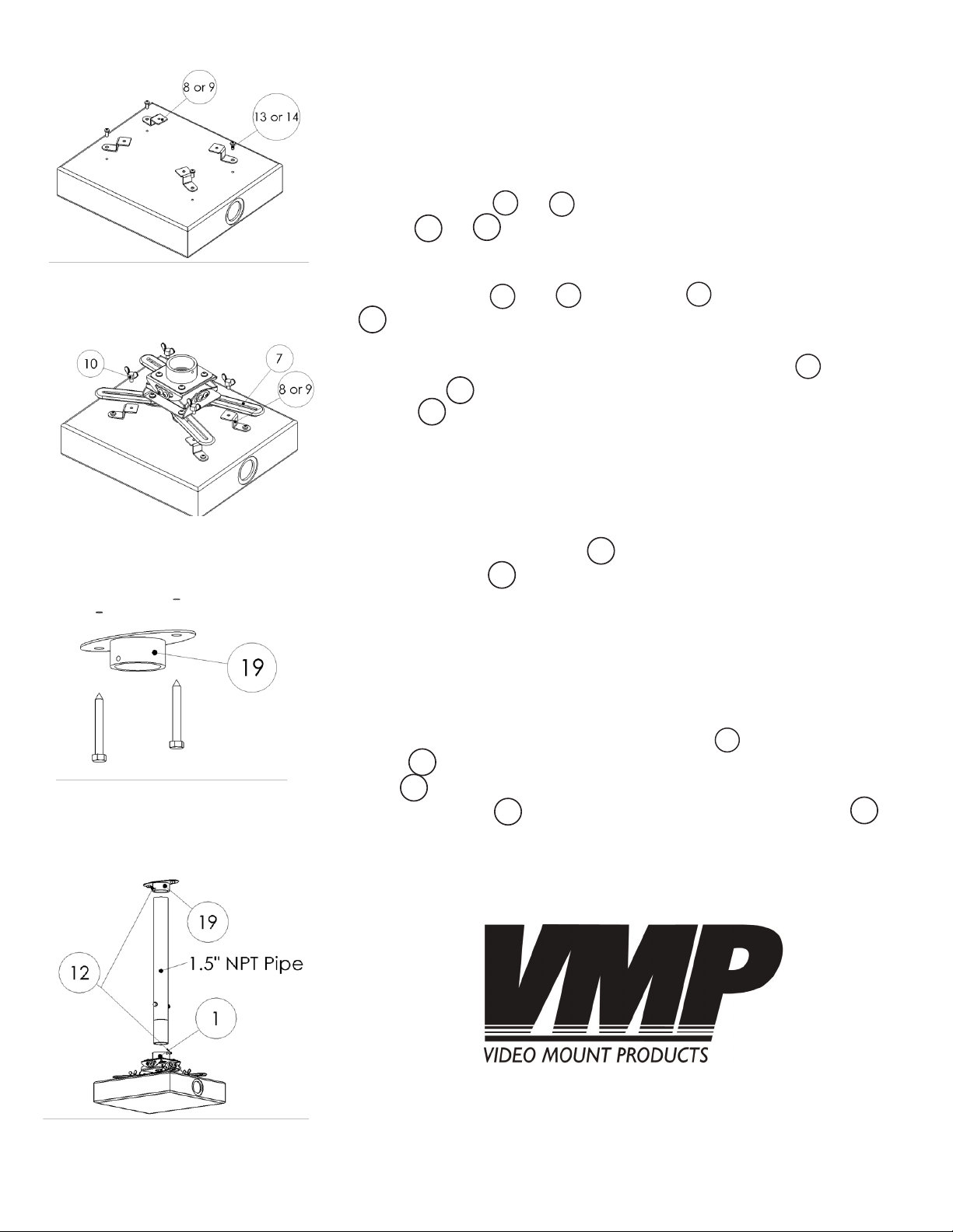
Step 2
Attach the feet or to the projector using the appropriate
screws or .
Step 3
Attach the feet or to the legs using the wing screws
. Note: If you plan to feed the cables through the holes in
the center of the mount itself take the time to do so now before
proceeding further. Note: If using the longer feet use the
M6 screws in the rear holes of the feet in addition to the wing
screws to better secure the longer foot.
If you are using the ceiling plate (#19) otherwise proceed to step 5.
Step 4
Mark the ceiling or desired mounting surface in preparation of in-
stallation of the ceiling plate . Pre-drill, if necessary, and mount
the ceiling plate to the desired surface. WARNING: Please ver-
ify that your mounting surface can support the combined weight of
your mount, mounting hardware and projector. Also verify that the
mounting surface is safe to drill through. If in doubt, please contact
a professional installer.
Step 5
Attach the 1.5” NPT pipe to the pipe couple . Tighten the brake
screw into the pipe to secure in place. If you use the ceiling
plate provided, secure the other end of the 1.5” NPT pipe into
the ceiling plate by tightening the second brake screw in
the other end of the pipe.
Please verify that all nuts and screws are securely tightened.
Step 2: Attaching the feet to
the projector
Step 3: Attaching the feet to
the mount
WARNING: The installer of these products must verify that the mount
surface, ceiling or wall, will safely support the combined weight of
all attached equipment and hardware. Video Mount Products will
not be held liable for the improper use or installation of its products.
Enjoy Your Mount!
Step 5: Attaching the mount
to the 1.5” NPT pipe
1
89
7
14
Step 4: Attaching the ceiling
plate to the mounting surface
13
10
89
9
10
15
19
19
19
12
12
19