Installation Instructions SLB-U
6
STEP 2
Adjusting the Legs on SLB-U
The mounting holes on projectors are supplied in a
variety of different patterns. There is no standard
mounting-hole configuration pattern for projectors.
The SLB-U will generally accommodate the mounting-
hole pattern on most projectors, providing that the SLB-U
adjustable legs can be configured to match the mounting
holes on your projector.
Due to the number of configurations that the SLB-U can
accommodate, this instruction guide only provides
guidance for the three most commonly used SLB-U
configurations on projectors. Select the applicable
procedure to mount the SLB-U on your projector:
• Step 2 (Option A). Align the SLB-U on a projector
with 4 mounting holes.
• Step 2 (Option B). Align the SLB-U on a projector
with 3 mounting holes.
• Step 2 (Option C). Align the SLB-U on a projector
using horizontal slot and 3 mounting holes.
• Step 2 (Option D). Align the SLB-U on a projector
using direct mounting option.
STEP 2 (OPTION A)
Aligning the SLB-U (as shipped) on a Projector
with 4 Mounting Holes
Align the SLB-U on the projector, as follows:
1. Locate the four mounting holes on your projector.
2. Using a Phillips screwdriver, loosen the four screws.
Do not remove the screws.
NOTE: If necessary, use the measurements that you
recorded when you completed Step 1,
“Measuring the Mounting Holes On Projector” to
help align the adjustable legs with the mounting-
hole pattern on the projector.
3. Align the SLB-U on projector, as follows:
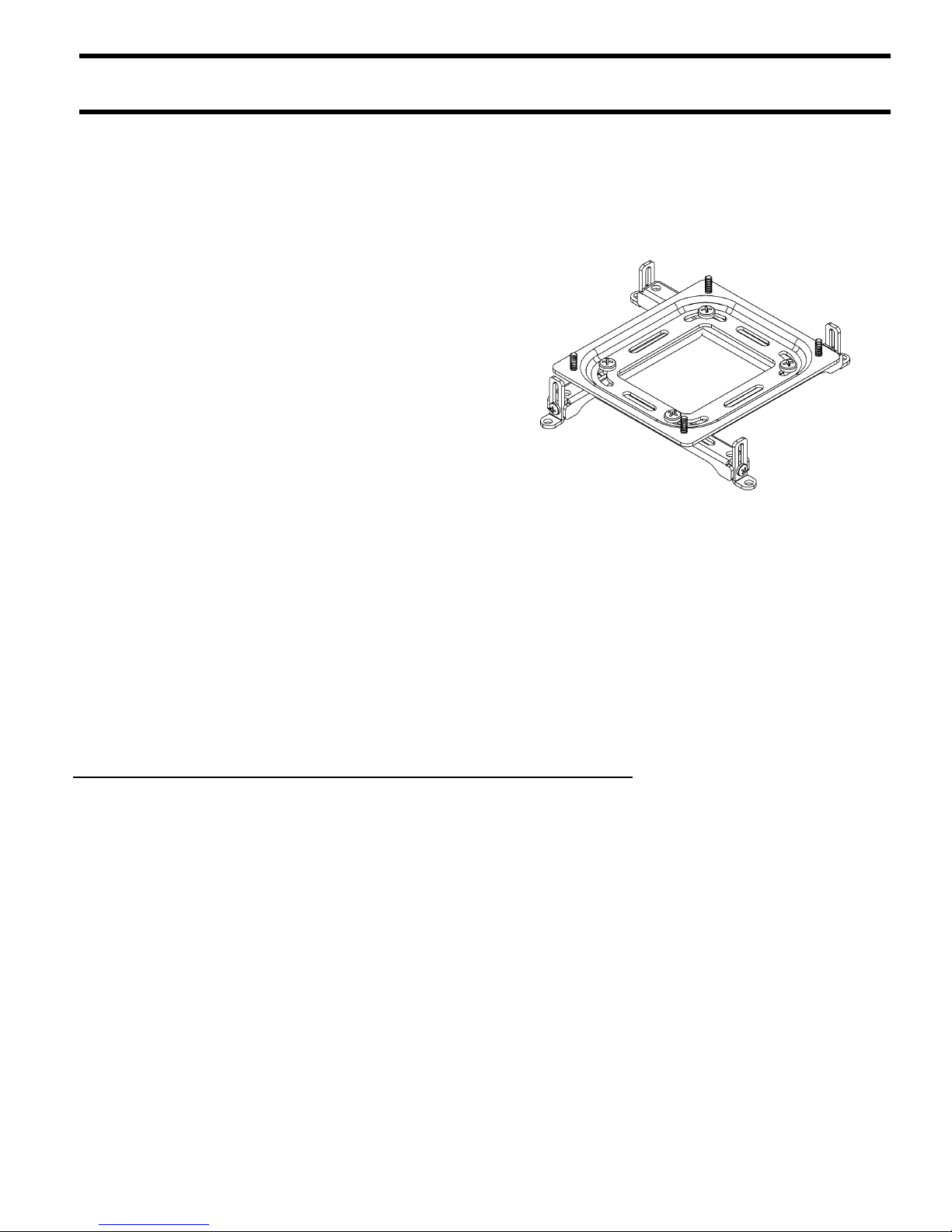
a. Place the SLB-U (10) on your projector.
b. Adjust the legs on the SLB-U (10) as needed.
Align the adjustable legs on the SLB-U with
mounting holes on your projector.
4. Attach the SLB-U to the projector, as follows:
a. Select the screw size that fits the threaded inserts
on your projector (see Table 3).
b. Select the washer that fits the selected screw.
c. Attach the SLB-U to the projector using the
selected fasteners in accordance with Table 3. Do
not tighten the screws at this time.
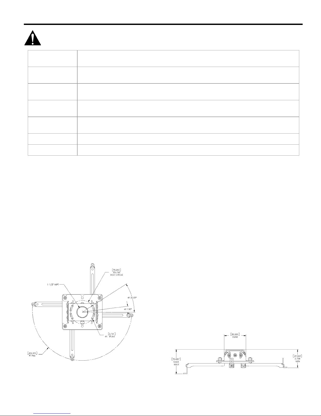
5. Attach the SLB-U to RPA (see Figure 2).
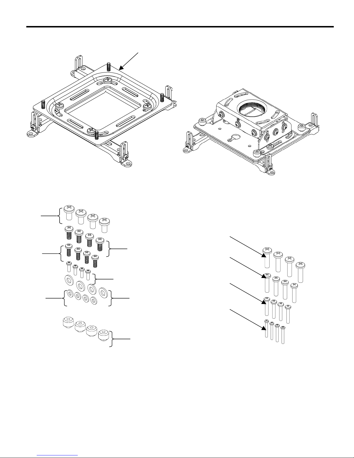
Table 3. SLB-U Mounting Hardware
ITEM DESCRIPTION QTY NOTES
20 M6 X 12MM SCREW 4
30 M5 X 12MM SCREW 4
USE ITEM 60 WITH
ITEMS 20 AND 30
40 M4 X 12MM SCREW 4
50 M3 X 10MM SCREW 4
USE ITEM 70 WITH
ITEMS 40 AND 50
60 M6 FLAT WASHER 4
70 M4 FLAT WASHER 4
80
10-24
THUMB NUT 4
USE TO ATTACH
SLB-U TO RPA
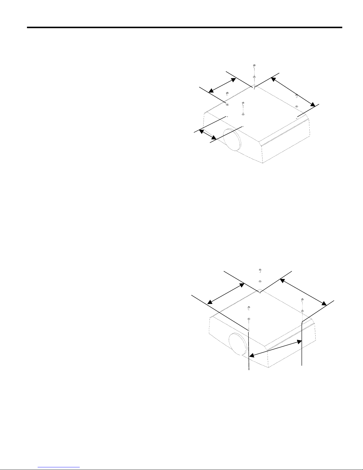
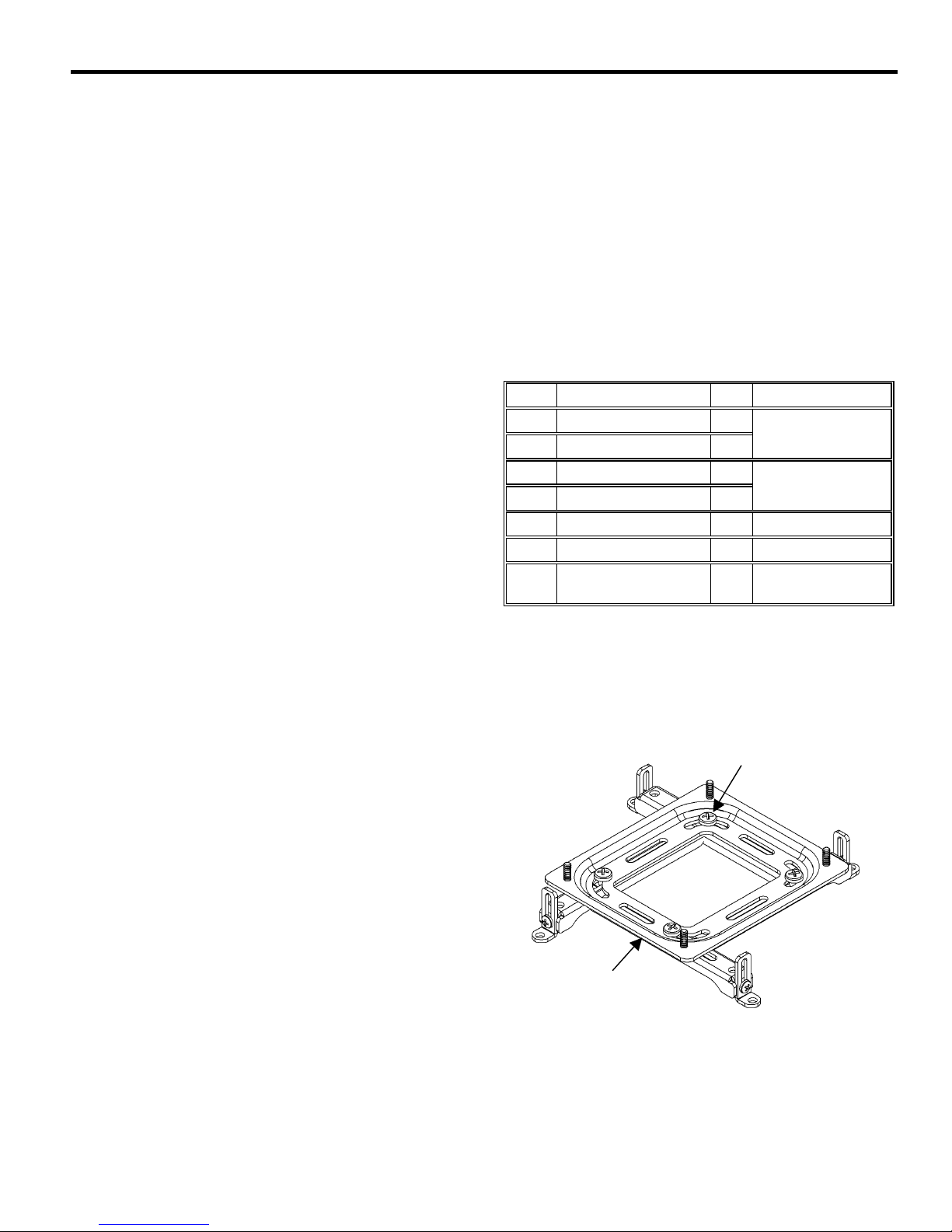
Figure 7. Align the SLB-U on 4-Hole Projector
10
Loosen screws. Adjust legs
on SLB-U, as needed. Align
legs on SLB-U with
mounting holes on projector.