Nexus 21 L-45en User manual

TV Lift System Model L-45en
Installation Instructions

2
3
Contact: Sup[email protected]
Toll Free: (866) 500-5438
Phone: (480) 951-6885
Fax: (480) 951-6879
Revised: 6/24/15
Below is a parts list describing all of the items included with the Model L-45en Lift System. You may
also wish to refer to the diagram shown on “Supplemental Page A” (at the end of this document).
Before beginning assembly and installation, please make sure that you have all items included on the
list. If any parts are missing or damaged, please contact Nexus 21. Our contact information is shown
at the top of this page.
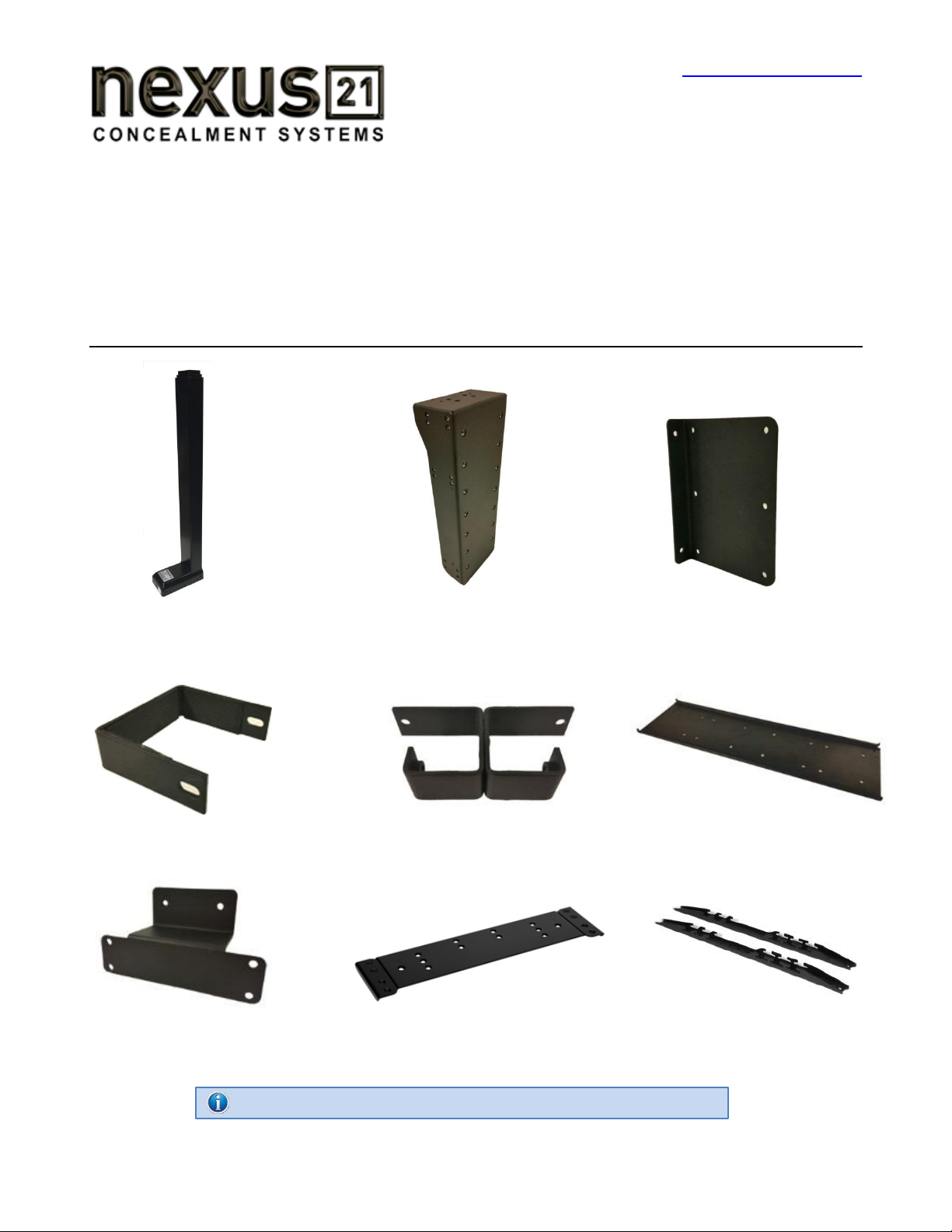
Parts List
1. L-45 Lift Column 2. Screen Support Bracket 3. Base Plate Bracket (2)
(28 ½” x 7” x 3 ¾”) (17 ½” x 6 ¼” x 3 ½”)(7 x 5 1/8” x 2”)
4. Upper Support Bracket 5. Upper Support Bracket Base 6. Screen Back Plate
(3”x 3 ½” x 1”) (4 ¾” x 2 1/8” x 7”) (32” x 8 ¾” x ½”)
7. Lower Support Bracket 8. Top Plate Bracket 9. Vertical Mounting Bar (2)
(6 ¼” x 4” x 2 ½”) (18 ¼” x 8 ½” x ½”) (20” x 1” x ¾”)
NOTE: Items 6 & 9 are included in the “Nexus 21 Standard TV Mount” package.
4
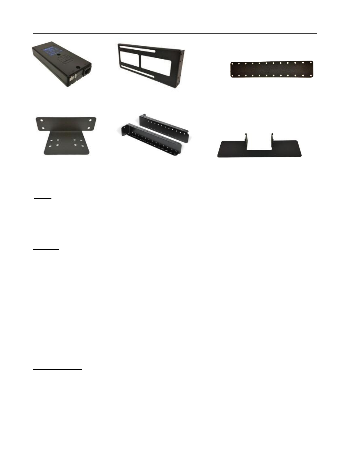
Parts List, continued
10. Control Box 11. Side Panel Bracket (2) 12. Accessory Mounting Bracket (2)
(10 ½” x 3 ¾” x 1 ½”) (14” x 1 ¾”) (2 ¼” x 11 ½”)
13. Rear Panel Bracket 14. Top Support Bracket (2) 15. Bottom Panel Bracket
(6 ¾” x 2” x 3 ½”) (14” x 2 ¾” x 1 1/8”) (20” x 5” x 3 ¼”)
Cables
Motor Cable –Black cable with white, six-pin plugs. Use this cable to connect the Lift Column to the Control Box
(using slot #1 on the Control Box). Three feet long.
Power Cable –Connects Control Box to power outlet. Three feet long.
RF Cable (only present if you ordered the RF version of the Lift System) –Use to connect the RF Receiver to the
Control Box. Ends have telephone-style connectors. One foot long.
Hardware
16.Two (2) -- Screen Locks (In bag labeled PDM-0108 - Located in box with Part #6 and #9)
17. Four (4) -- 6mm x 16mm Button Head Machine Screw
18.Four (4) –6mm x 16mm Flat Head Machine Screw
19. Thirty-Two (32) -- 6mm x 10mm Button Head Machine Screw
20. Two (2) -- 1½” x ¼” Steel Threaded Taper Pins (For Floating Top)
21. Twelve (12) -- 3/8 - 16 x ¾” Button Head Machine Screw
22.Eight (8) –3/8 Nyloc Hex Nuts
23. Two (2) -- #10 x 1 ¾” Flat Head Wood Screw
24. Forty-Six (46) -- #10 x ¾” Truss Head Wood Screw
25. Four (4) -- #8 x ¾” Flat Head Wood Screw
26.RF Controls or IR Controls (see explanation on page 6)
27.Two (2) -- Allen Wrenches –4mm and 7/32”
28.Four (4) -- Square Multi Mount Washers
29.Four (4) -- Lid Catch Brackets w/ (8) #10 x ¾” THWS
30.One (1) -- Bag of Assorted TV Mounting Screws
Wire Management
31.One (1) -- “Snakeskin” Wire Management Sleeve – 4 feet long
32. Four (4) -- Velcro end Ties, for use with Wire Management Snakeskin
33. Four (4) -- Plastic Ties, also for use with Wire Management Snakeskin
34. Four (4) –Wire Clips
5
SAFETY INFORMATION
SEVERE PERSONAL INJURY AND PROPERTY DAMAGE CAN RESULT FROM IMPROPER INSTALLATION
OR ASSEMBLY. READ THE FOLLOWING WARNINGS BEFORE BEGINNING:
WARNINGS:
1. Do not use this product for any application other than those specified by Nexus 21.
2. Do not exceed the weight capacity. This can result in serious personal injury or damage to the equipment. It is the installer’s
responsibility to ensure that the total combined weight of all attached components does not exceed that of the maximum
figure stated.
3. Follow all technical specifications and instructions during the installation.
4. Only use attachments/accessories specified by the manufacturer.
5. Close supervision is necessary when this system is being used by, or near, children, or disabled persons.
6. It is the responsibility of the installer to warn all potential users of the dangers of interfering with the mechanism during
operation.
7. Read all technical instructions fully before installation and use. It is the installer’s responsibility to ensure that all
documentation is passed on the users and read fully before operation.
8. Failure to provide adequate structural strengthening, prior to installation can result in serious personal injury or damage to
the equipment. It is the installer’s responsibility to ensure the structure to which the Lift System is affixed can support four
times the weight of the system.
9. Risk of electric shock. Do not attempt to open the Control Box.
10. To reduce risk of fire or electric shock, do not expose parts to rain or other liquids.
11. Protect the power cord from being walked on or pinched.
12. Keep all documentation.
13. Heed all warnings.
14. Clean only with a dry cloth.
15. Refer all service questions to Nexus 21 if the system does not operate normally.
Nexus 21 disclaims any liability for modifications, improper installations, or installations over the specified weight range. Nexus 21 will not be liable for
any damages arising out of the use of, or inability to use, Nexus 21 products. Nexus 21 bears no responsibility for incidental or consequential damages.
This includes, but is not limited to, any labor charges for the servicing of Nexus 21 products performed by anyone other than Nexus 21.
Nexus 21 intends to make this and all documentation as accurate as possible. However, Nexus 21 makes no claim that the information contained herein
covers all details, conditions or variations, nor does it provide for every possible contingency in connection with the installation or use of this product. The
information contained in this document is subject to change without prior notice or obligation of any kind. Nexus 21 makes no representation of
warranty, expressed or implied, regarding the information contained herein. Nexus 21 assumes no responsibility for accuracy, completeness or
sufficiency of the information contained in this document.
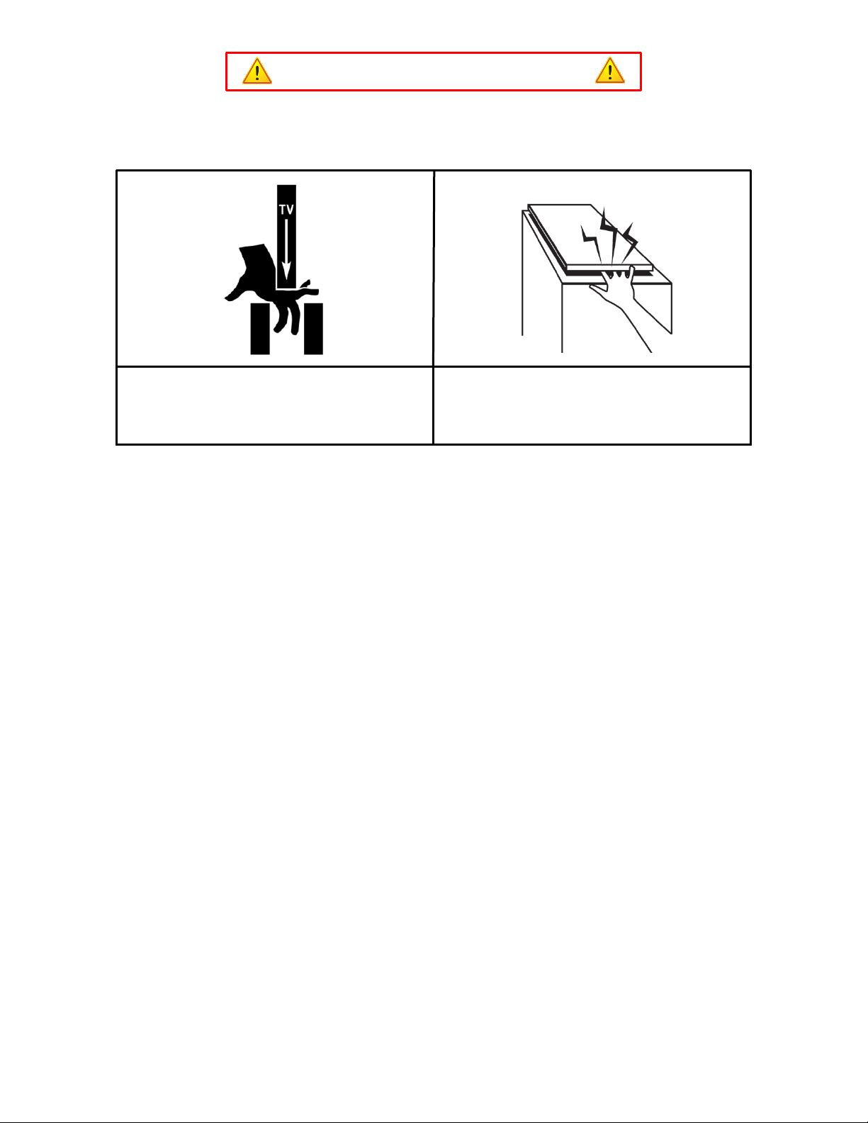
CABINET LID HAZARD
TV HAZARD
CAUTION: Avoid contact with the TV and Lift System during
operation. Use with caution.
CAUTION: The cabinet lid must be installed as described in the
instructions, using the Steel Threaded Tapered Pins. Installing
the cabinet lid in any other fashion will create hazardous pinch
points that can cause serious personal injury.

6
Types of Controls for Nexus 21 Lift Systems
All Nexus 21 Lift Systems come standard with a wireless remote control and receiver. We offer a choice of two different
types of remotes: IR and RF (both of which are explained in detail below). Our standard control type is RF, so unless you
specifically requested the IR version when you made your purchase, you probably received the RF controls with this Lift
System. The method of installation for each type of remote control is slightly different, so you should now identify which
type of remote you have by reading below, and then follow the instructions for that type of remote.
NOTE: If you will be using the Lift with a home control system (like the ones made by companies such as Crestron or
Control 4) the most common form of control is to WIRE IT DIRECTLY to the relays of your home control system. This
direct-wire method is called Integration by Contact Closure, and is accomplished by using the Backup Control Switch
(Height Limit Switch) that was supplied with the Lift System to connect the Lift to the control unit from your home control
system.
Before You Begin the Installation: Identify Your Control Type
IR (Infrared) –This control option allows you to utilize a 3rd party universal style remote control to raise and lower the
TV Lift. Your universal remote will “learn” the IR codes from the provided IR Handset, which will enable you to control the
lift. The universal remote will then communicate with the “eye” located on the IR Receiver via your 3rd party emitter (or
flasher). Instructions for mounting the IR controls are on page 13. Instructions for setting the TV Lift’s travel limit are on
Supplemental Page B.
NOTE: If you are NOT planning on using a 3rd party Universal Remote, switch to the RF setup. (There is no charge for swapping)
These are the parts included with IR controls:
Contact Closure Hardware IR Receiver IR Handset Height Limit Insert
RF (Radio Frequency) - This system utilizes a wireless remote control handset that sends a radio signal to the RF
Receiver. The radio signal can go through cabinet walls and does not require line-of-sight. Instructions for mounting the
RF controls are on page 14. Instructions for setting the Lift System travel limit are on Supplemental Page B.
TIP: Planning to integrate the TV Lift with your UNIVERSAL REMOTE CONTROL? The RF version of the Nexus 21 controls won’t do
it. Switch to IR.
These are the parts included with RF controls:
Backup Switch RF Receiver RF Handset Height Limit Insert
Integration by Contact Closure –To direct-wire the TV Lift controls to a home control system (Crestron, Control 4,
AMX, etc.) you will use the Back-up Control Switch (Height Limit Switch). You won’t use any Nexus 21 receiver or handset
for this type of control because you will use the handset or control pad that comes with your home control system.
Instructions for setting up the System using Contact Closure are on “Supplemental Page C”.
7
Assembly and Mounting –Things to Think About First
SAFETY NOTICE:
For proper support, the Lift System MUST NOT be attached to any material that is less than ¾” thick. This
applies to BOTH the back and bottom mounting points.
The Lift Column is ONLY designed and rated for VERTICAL, NON-INVERTED USE. DO NOT MOUNT THIS
LIFT SYSTEM UPSIDE DOWN or SIDEWAYS (HORIZONTALLY, AS IN A LATERAL MOUNT)!
Space requirements for the L-45en Lift System are as follows:
Interior Box Depth = TV Depth + 5”, or 6.5”, whichever is greater.
Interior Box Height = TV Height +“1, Not to Exceed 35” (Exterior Height not to exceed 35.5).
Interior Box Width = TV Width + 1”.
Interior Cabinet Depth = Interior Box Depth + 2.375” or 11.25”, whichever is greater.
Interior Cabinet Height = Box Height + 2.5”, Not to exceed 37”
Interior Cabinet Width = Exterior Box Width plus 1”
Lid Depth = Interior Box Depth +Back Panel Thickness +1.25” or 8.75 whichever is greater.
Lid Width = Exterior Box Width +1”
IMPORTANT NOTE: The TV must be mounted as high up as possible inside the cabinet, so that when the Lift is in
the fully “DOWN” position (fully retracted), the top of the TV will be just underneath the lid of the cabinet.
About the Cabinet Lid (Cabinet Top)
SAFETY NOTICE:
WARNING! YOU MUST NOT DIRECTLY SCREW THE CABINET LID (TOP) TO THE LIFT SYSTEM!! THIS
CREATES HAZARDOUS “PINCH POINTS” AND MAY AFFECT THE OPERATION OF THE LIFT OR CAUSE DAMAGE TO
THE CABINET TOP.
For floating lids, DO NOT USE SCREWS to attach the lid to the Lift System. Instead, use the “Threaded
Taper Pins”. This will keep the lid firmly in place, but will also allow it to separate from the lift system if anything
(like a finger) gets in the way when the TV lowers.
Which Lid Style Will You Use? (There are 3 Different Styles)
Floating Lid (Floating Top) –The whole top of the cabinet sits on top of the Lift System and raises/lowers with the TV.
This is the standard Installation method, using the Top Plate (part #8) and Threaded Taper Pins.
Cut-Out Floating Lid (Top) –You will “cut out” part of your cabinet top, customizing it to the size of your TV. That cut-out
lid then sits on top of the Lift System and raises/lowers with the TV. This method uses the Top Plate (part #8) and
Threaded Taper Pins (Part #20), but you must set up a “catch” for the cut-out lid so that when the TV lowers, the lid stops
level with the rest of your cabinet top (like a manhole cover).
Hinged-Lid (Hinged-Top) –Not Compatible with the L-45en Lift System.

8
You Are Ready to Begin
Please perform the following steps, in order:
Step 1: Inventory the Parts List. Carefully inspect all items, making sure you have everything in the Parts List
on page 1. Be sure to open the Nexus 21 TV Mount carton that includes parts #6, #9 and #17.
Step 2: Attach both Base Plates to the bottom of the Lift Column. Using (4) 6mm x 10mm Button Head
Machine Screws (BHMS), attach (1) Base Plate to each side of the base of the Lift Column (two screws per side).
Do Not Over Tighten.
Step 3: Attach the Lower Support Bracket. Using (2) 6mm x 10mm Button Head Machine Screws (BHMS)
attach the Lower Support Bracket to the rear of the base of the Lift Column. Do Not Over Tighten.

9
Step 4a: Attach the Upper Support Bracket. Slide the Upper Support Bracket around the outer profile. Make
sure the Upper Support Bracket sits just above the Nexus 21 label for optimal support.
Step 4b: Attaching the Upper Support Bracket Base (Part #5). Using (2) 6mm x 10mm Button Head Machine
Screws (BHMS) attach the Upper Support Bracket Base to the Upper Support Bracket. Make sure to hold the
Upper Support Bracket Base firmly against Lift Column while tightening the screws, to ensure there is no lateral
movement.

10
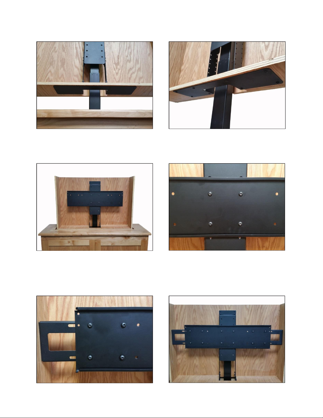
Step 5: Attach the Screen Support (Part #2) and Rear Panel Bracket (Part #13) to the top of the Lift Column.
Align the four threaded holes on top of the Lift Column with the four countersunk holes on the Screen Support
and the four center holes of the Rear Panel Bracket. Using (4) 6mm x 16mm BHMS fasten both brackets to the
top of the Lift Column.
Step 6: Attach the Bottom Panel Bracket (Part # 14) to the Accessory Mounting Brackets (Part #12). Using (8)
6mm x 10mm BHMS Screws (4 screws per bracket) fasten both Accessory Mounting Brackets to the Bottom
Panel Bracket. NOTE: Make sure you use the lower most four holes on the Accessory Mounting Brackets.
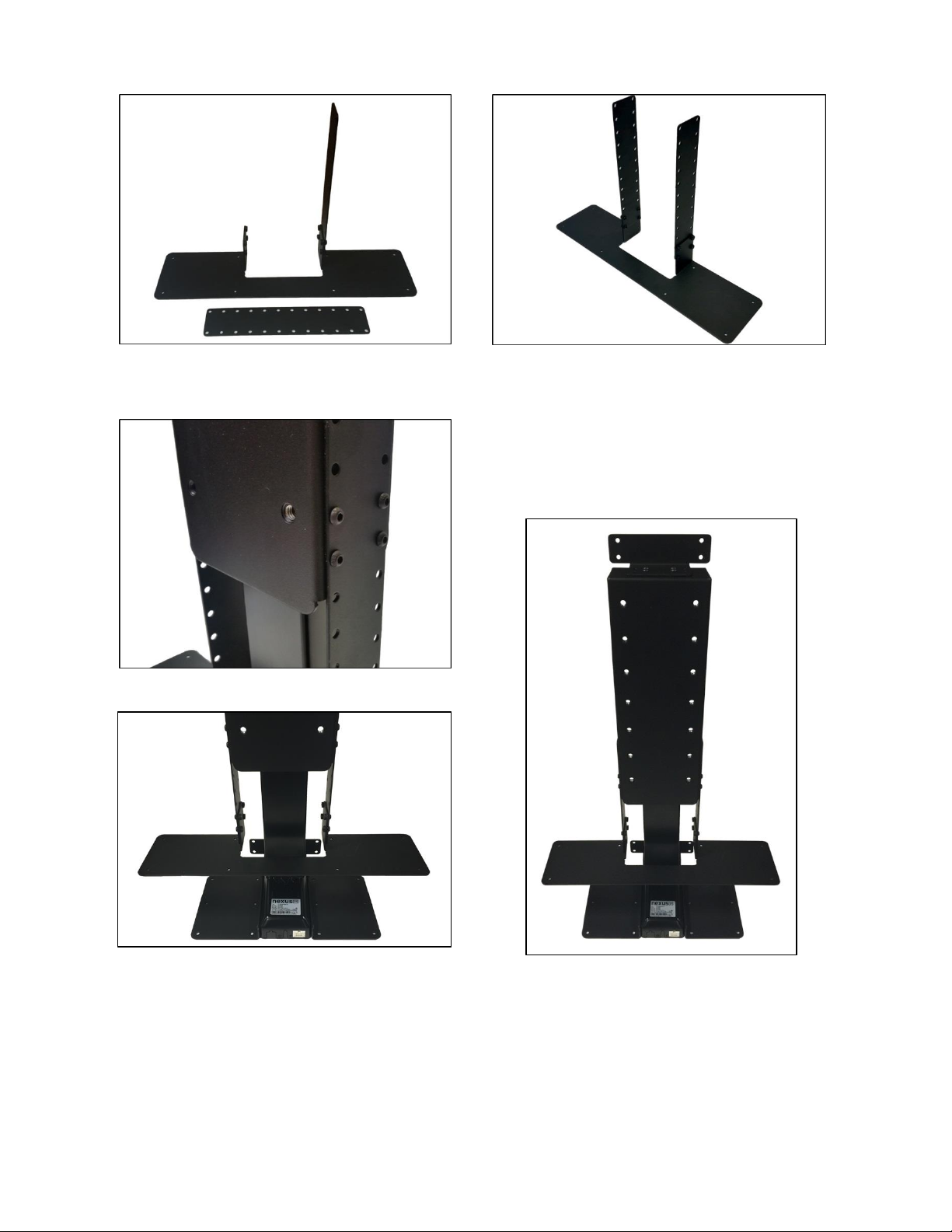
11
Step 6 Continued:
Step 7: Attach the assembled Lower Panel Bracket to the Screen Support Bracket. Using (8) 6mm x 10mm
BHMS Screws (4 screws per side), fasten the Lower
Panel Bracket to the Screen Support Bracket using
the 3rd and 4th holes from the top of the Accessory
Mounting Brackets.

12
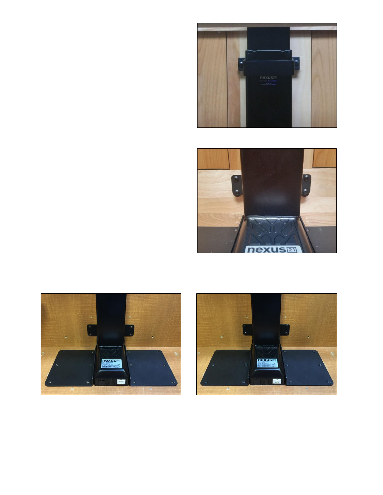
Step 8: Place Lift Column inside cabinet and make sure
to center the Lift Column from left to right.
Step 9: Mount the Control Box and controls to the wall at a nearby accessible location: Using (2) #10 x 1 ¾”
FHWS mount the Control Box to the wall. Using (2) #8 x ¾” THWS mount the Wired Back Up Switch. If you
ordered IR Controls, then you will use (2) #8 x ¾” FHWS to mount the IR Receiver. If you ordered RF Controls,
then you will use (2) #6 x ¾” RHWS to mount the RF Receiver.
Step 10: Please refer to the IR Controls Wiring Diagram on the following page, if you ordered RF Controls
continue to page 13. Ensure that the motor cable is connected to port #1. The lift will not operate if motor
the cable is connected to ports #2 or #3.

13
IF YOU HAVE IR CONTROLS, USE THIS DIAGRAM (for RF Controls, see the following page)
Once you have connected the controls, test the Lift Column as follows:
First, you need to “initialize” the Lift System. If you have already raised the Lift Column, lower it again, since this step must be
performed in the “down” position. Find the Wired Backup Switch, which has two triangle-shaped buttons - an UP (with raised dot) and
a DOWN. Press the DOWN button and HOLD IT DOWN for approximately 5 seconds. You should see a slight movement in the Lift
Column. If you do not see the movement, release the Down button, and repeat the process - press and hold the Down button again for
5 seconds. Once you have seen the slight movement, the Lift System is now functional. Test it by pressing the Up button (no need to
hold the Up button) and the lift will go up. You may let it go to the top, or stop it at any time by pressing the Down button.

14
IF YOU HAVE RF CONTROLS, USE THIS DIAGRAM (for IR Controls, see the previous page)
Once you have connected the controls, test the Lift Column as follows:
First, you need to “initialize” the Lift System. If you have already raised the Lift Column, lower it again, since this step must be
performed in the “down” position. Find the Wired Backup Switch, which has two triangle-shaped buttons - an UP (with raised dot) and
a DOWN. Press the DOWN button and HOLD IT DOWN for approximately 5 seconds. You should see a slight movement in the Lift
Column. If you do not see the movement, release the Down button, and repeat the process - press and hold the Down button again for
5 seconds. Once you have seen the slight movement, the Lift System is now functional. Test it by pressing the Up button (no need to
hold the Up button) and the lift will go up. You may let it go to the top, or stop it at any time by pressing the Down button.
15
Step 11: Attach the Upper Rear Support Bracket to
the rear panel of your cabinet. Fully extend the
Lift Column. Using (2) #10 x ¾” THWS Screws fasten
the Upper Rear Support Bracket to the rear panel of
the cabinet.
Note: Make sure to center the Lift Column from left
to right.
Step 12: Attach the Lower Rear Support Bracket to
the rear panel of your cabinet. Using (4) #10 x ¾”
THWS Screws fasten the Lower Rear Support Bracket
to the rear panel of the cabinet.
Step 13: Attach both Base Plate Brackets to the base of the cabinet. Using (12) #10 x ¾” THWS Screws (6
screws per side) fasten both Base Plate Brackets to the base of the cabinet.
NOTE: Step 14a - 14c assumes all joints are Butt Joints when determining the dimensions for each Panel.
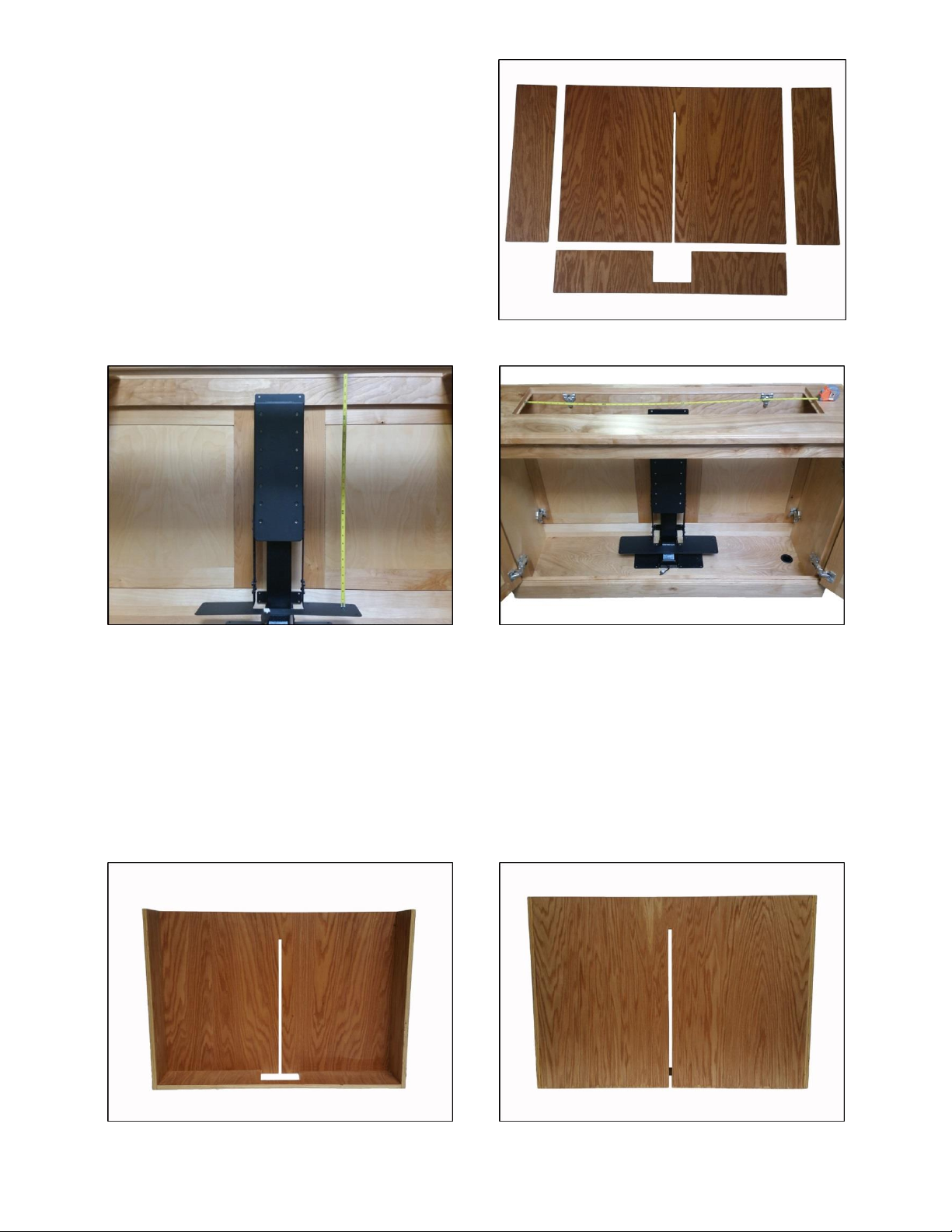
16
Step 14a: Determining Interior Box dimensions. Lower
the Lift Column to the fully retracted position. Measure
the distance from the top of the Bottom Panel Bracket
to the “Lip” or “Corner Catches” the lid will rest on
when the lift is in the fully retracted position. This
measurement will determine the height of the rear and
side panel dimension. Measure the width of the opening
and subtract ½” plus your material thickness x 2, which
will give you the rear panel width measurement.
NOTE: You will need to cut a ½” thick slot, 26 inches up
the rear panel, starting from the bottom up. This will
allow the Upper Rear Support Bracket to slide into,
when the lift is fully retracted.
Step 14b: Determine the side panel dimensions. Measure the lid opening depth from front to back, subtract
your rear panel material thickness plus ½” from the lid opening depth measurement. This will determine the
width measurement for both side panels. You will use the height measurement from the previous step as the
height measurement for both side panels.
Step 14c: Determine the bottom panel dimensions. The bottom panel should be the same width as the rear
panel, which was determined in Step 14a. Measure the depth of the lid opening and subtract ½” plus the
material thickness. This will give you the depth of the bottom panel. NOTE: You will need to cut a 7.5” x 5.5”
rectangle in the center of the bottom panel, on the back edge of the bottom panel. This cut will allow you
to slide your Interior Box down over the Screen Support Bracket.
17
Step 15a: Attach the constructed Interior Box to the lift system. Raise the lift system, so the Bottom Panel
Bracket is flush with the top of the cabinet. Slide the Interior Box over the Screen Support Bracket and allow
the Interior Box to rest on the Bottom Panel Bracket.
Step 15b: Fasten the Rear Panel Bracket to the rear panel of the Interior Box. Using (4) #10 x ¾” THWS Screws
fasten the Interior Box to the Rear Panel Bracket. NOTE: Make sure to center the Interior Box within the
opening of the cabinet on all sides.
Step 16: Test Run the Lift System. Run the lift up and down a few times to make sure the Upper Rear Support
Bracket does not rub or bind up on the ½” slot in the rear panel of the Interior Box.
18
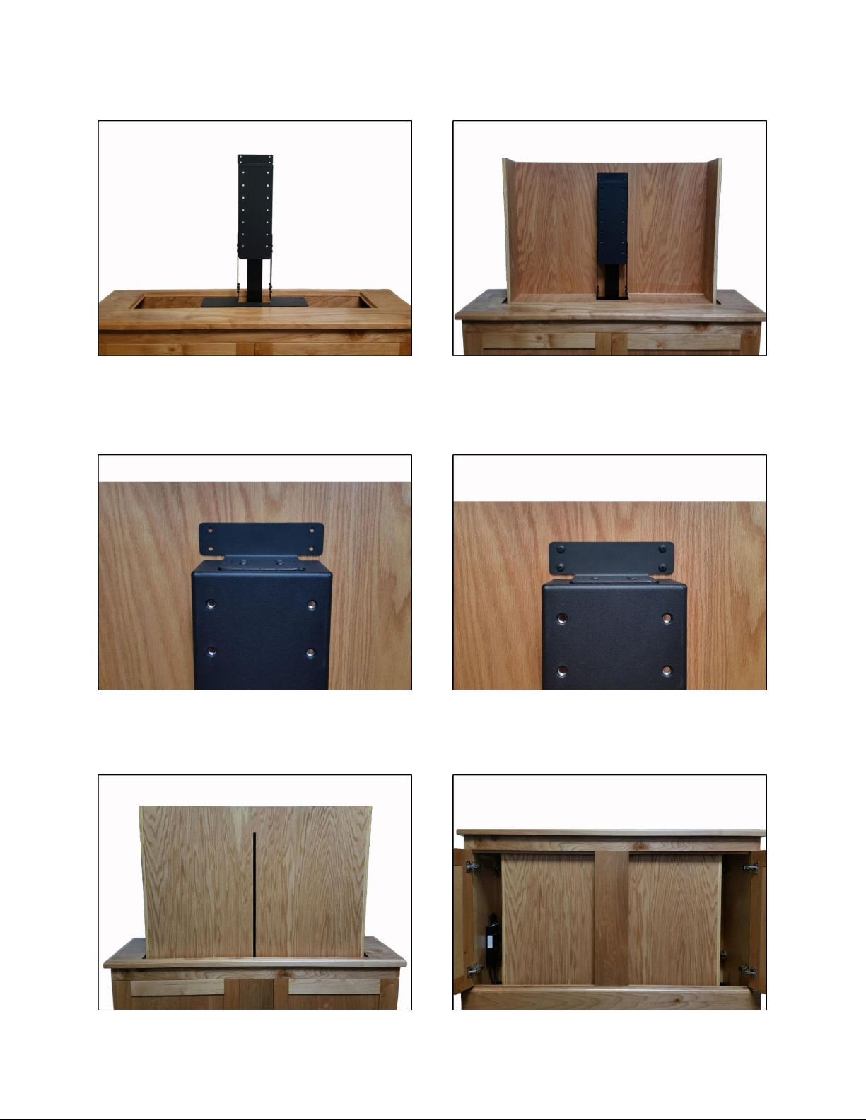
Step 17: Attach the Bottom Panel Bracket to the bottom panel of the Interior Box. Using (8) #10 x ¾” THWS
Screws fasten the Bottom Panel Bracket the bottom side of the Interior Box.
Step 18: Attach the Screen Back Plate (Part #6) to the Screen Support. Using (4)3/8” x 16 BHMS Screws fasten
the Screen Back Plate to the Screen Support. Make sure to center the Screen Back Plate on the Screen Support.
Step 19a: Attach the Side Panel Brackets to the Screen Back Plate. Using the four outer holes on both side of
the Screen Back Plate use (8) 3/8” x 16 x ¾” BHMS Screws and (8) 3/8” x 16 x ¾” Hex Nyloc Nuts (4 screws and
nuts per side) to fasten both Side Panel Brackets to the Screen Back Plate. NOTE: For larger Interior Boxes, only
two of the four 3/8” BHMS holes will be useable.

19
Step 19b: Attach the Side Panel Brackets to the side panels of the Interior Box. Using (16) #10 x ¾” THWS
Screws (8 screws per bracket) fasten both Side Panel Brackets to each side panel of the Interior Box.
Step 20: Attach the Top Support Brackets (Part #14) to the Screen Support Bracket. Using (8) 6mm x 10mm
BHMS Screws (4 Screws per bracket) fasten the both Top Support Brackets to the both sides of the Screen
Support Bracket. NOTE: Make sure to position the Top Support Brackets so the top of the brackets are a
¼” – ½” below the top edge of the Interior Box. There are two sets of PEM Nuts on the sides of the Screen
Support Bracket, which will give you ½” adjustments.

20
The Top Plate Bracket (Part #8) is a 5-part plate (one Main Plate, two Extensions and two Fine-tuning Plates)
that allows you to adjust the depth and position of the plate relative to the Threaded Tapered Pins (Steps 22-
27). The Top Plate Bracket comes pre-assembled in a semi-retracted configuration. If you need to expand the
depth of the plate to accommodate a deeper cabinet lid, remove the flat head machine screws from the
Extensions, move them to the depth you need, and re-insert the machine screws. Fully retracted, the Top
Plate Bracket has a depth of 6 ½”, and can be adjusted to 7 ½” and 8 ½” with the Extensions on either end of
the plate. (See Photo Below)
Step 21: Attach the Top Plate Bracket (Part #8) to both Top Support Brackets. Using (4) 6mm x 16mm FHMS
Screws attach the Top Plate Bracket to both Top Support Brackets using the four outermost countersunk holes.
NOTE: Do not bolt/screw the Lid to the Top Plate. Use the provided Tapered Pins to attach the Lid to the lift
system. The Tapered Pins allow the lid to lift away when there is an obstruction. See the following page for
further details.
Table of contents
Other Nexus 21 TV Mount manuals

Nexus 21
Nexus 21 ML-65 User manual

Nexus 21
Nexus 21 XL-75s User manual

Nexus 21
Nexus 21 L-45ens User manual

Nexus 21
Nexus 21 DL-50 User manual

Nexus 21
Nexus 21 Transcend Pro User manual

Nexus 21
Nexus 21 DL-50b User manual

Nexus 21
Nexus 21 L-85s User manual

Nexus 21
Nexus 21 L-75s Installation guide

Nexus 21
Nexus 21 L-65 HTG User manual

Nexus 21
Nexus 21 L-50s User manual
Popular TV Mount manuals by other brands

AVARRO
AVARRO NX-FMSA1337 manual

SANUS VuePoint
SANUS VuePoint FPA701 instruction manual

peerless-AV
peerless-AV PLAV70 Installation and assembly

Spectrum Industries
Spectrum Industries 55534 Assembly instructions

Goobay
Goobay TV EasyFix XL2 user manual

Elexa
Elexa Level mount ELSFW-01 installation instructions


