Nexus 21 XL-75s User manual
1
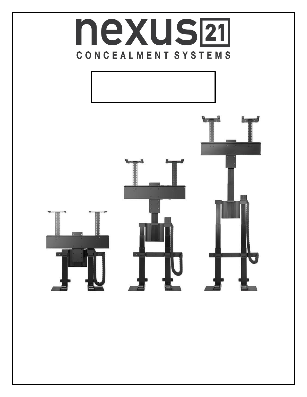
TV Lift System Model XL-75s
Installation Instructions
2
Contact: Sup[email protected]
Toll Free: (866) 500-5438
Phone: (480) 951-6885
Fax: (480) 951-6879
Revised: 07/07/16
Below is a parts list describing all of the items included with the Model XL-75s Lift System.
Before beginning assembly and installation, please make sure that you have all items included on the list. If
any parts are missing or damaged, please contact Nexus 21. Our contact information is shown at the top of
this page.
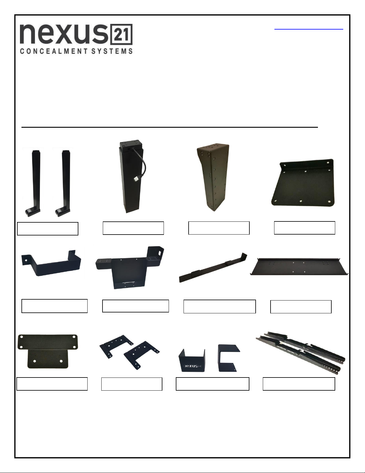
Parts List
Lower Lift Columns
Upper Lift Column
Screen Support
Base Plate
Upper Column Brace
Center Riser Bracket
Rear Support Bracket
Screen Back Plate
Lower Column Support
Top Plates
Lower Column Brace
Vertical Mounting Bars
3
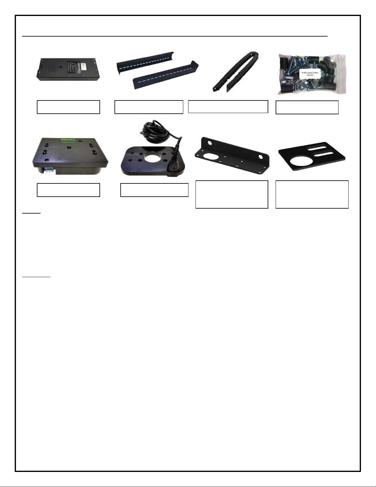
Parts List, continued
Cables
Motor Cables (3) –Black cable with white, six-pin plugs. Use these cables to connect the Lift Columns to the Control Box
(using slots #1, #2, and #3 on the Control Box). There are 3 Cables total, in 2 different sizes, 4.5m and 2.5m.
Power Cable –Connects Control Box to power outlet. Three feet long.
RF Cable (only present if you ordered the RF version of the Lift System) –Use to connect the RF Receiver to the Control
Box. Ends have RJ-45 connectors. One foot long.
Hardware
13. Eight (4) –5mm x 12mm Flat Head Machine Screw
14. Six (6) –6mm x 12mm Flat Head Machine Screw
15. Four (4) -- 6mm x 16mm Flat Head Machine Screw
16. Twelve (12) –6mm x 20mm Flat Head Machine Screw
17. Sixteen (16) –6mm x 10mm Button Head Machine Screw
19. Eight (8) -- 6mm x 12mm Button Head Machine Screw
20. Four (4) -- 3/8 - 16 x ¾” Button Head Machine Screw
21. Two (2) -- Screen Locks (In bag labeled PDM-0108)
22. Four (2) -- 1½” x ¼” Steel Threaded Taper Pins (For Floating Top)
23.Two (2) -- #10 x 1 ¾” Flat Head Wood Screw (For Backup Switch)
24. Thirty-Six (36) -- #10 x ¾” Truss Head Wood Screw
25. Two (2) -- #8 x ¾” Flat Head Wood Screw (For IR controls only)
26. RF Controls or IR Controls (see explanation on page 5)
27. Three (3) -- Allen Wrenches –3mm, 4mm and 7/32”
28. Four (4) -- Square Multi Mount Washers
29. Four (4) –Lid Catch Brackets w/ (8) #10 x ¾” THWS
Control Box
Top Support Brackets
Assorted Hardware
Cable Management Track
Swivel Mechanism
Swivel Adapter Plate
Right Cable
Management Bracket
Center Cable
Management Bracket
4
SAFETY INFORMATION
SEVERE PERSONAL INJURY AND PROPERTY DAMAGE CAN RESULT FROM IMPROPER INSTALLATION OR ASSEMBLY.
READ THE FOLLOWING WARNINGS BEFORE BEGINNING:
WARNINGS:
1. Do not use this product for any application other than those specified by Nexus 21.
2. Do not exceed the weight capacity. This can result in serious personal injury or damage to the equipment. It is the installer’s
responsibility to ensure that the total combined weight of all attached components does not exceed that of the maximum figure stated.
3. Follow all technical specifications and instructions during the installation.
4. Only use attachments/accessories specified by the manufacturer.
5. Close supervision is necessary when this system is being used by, or near, children, or disabled persons.
6. It is the responsibility of the installer to warn all potential users of the dangers of interfering with the mechanism during operation.
7. Read all technical instructions fully before installation and use. It is the installer’s responsibility to ensure that all documentation is
passed on the users and read fully before operation.
8. Failure to provide adequate structural strengthening, prior to installation can result in serious personal injury or damage to the
equipment. It is the installer’s responsibility to ensure the structure to which the Lift System is affixed can support four times the weight
of the system.
9. Risk of electric shock. Do not attempt to open the Control Box.
10. To reduce risk of fire or electric shock, do not expose parts to rain or other liquids.
11. Protect the power cord from being walked on or pinched.
12. Keep all documentation.
13. Heed all warnings.
14. Clean only with a dry cloth.
15. Refer all service questions to Nexus 21 if the system does not operate normally.
Nexus 21 disclaims any liability for modifications, improper installations, or installations over the specified weight range. Nexus 21 will not be liable for any damages
arising out of the use of, or inability to use, Nexus 21 products. Nexus 21 bears no responsibility for incidental or consequential damages. This includes, but is not
limited to, any labor charges for the servicing of Nexus 21 products performed by anyone other than Nexus 21.
Nexus 21 intends to make this and all documentation as accurate as possible. However, Nexus 21 makes no claim that the information contained herein covers all
details, conditions or variations, nor does it provide for every possible contingency in connection with the installation or use of this product. The information contained
in this document is subject to change without prior notice or obligation of any kind. Nexus 21 makes no representation of warranty, expressed or implied, regarding
the information contained herein. Nexus 21 assumes no responsibility for accuracy, completeness or sufficiency of the information contained in this document.
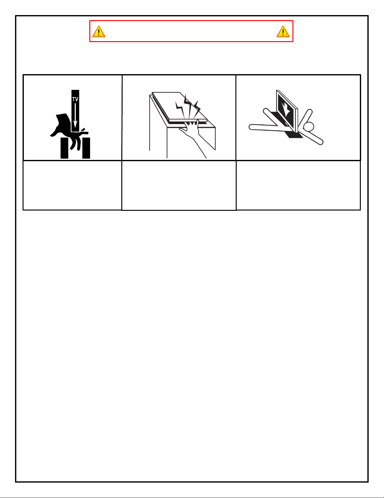
TV HAZARD
LID HAZARD
CAUTION: Avoid contact with the TV and
Lift System during operation. Use with
caution.
CAUTION: The lid of your enclosure must be
installed as described in the instructions, using the
Steel Threaded Tapered Pins. Installing the
enclosure lid in any other fashion will create
hazardous pinch points that can cause serious
personal injury. More info on page 25 & 26.
CAUTION: FOR UNDER FLOOR INSTALLATIONS ONLY:
Do not, under any circumstances, allow any person or
pet to position themselves underneath the TV at any
time.
UNDER FLOOR HAZARD
5
Types of Controls for Nexus 21 Lift Systems
All Nexus 21 Lift Systems come standard with a wireless remote control and receiver. We offer a choice of two different types of
remotes: IR and RF (both of which are explained in detail below). Our standard control type is RF, so unless you specifically
requested the IR version when you made your purchase, you probably received the RF controls with this Lift System. The method of
installation for each type of remote control is slightly different, so you should now identify which type of remote you have by
reading below, and then follow the instructions for that type of remote.
NOTE: If you will be using the Lift with a home control system (like the ones made by companies such as Crestron or Control 4) the
most common form of control is to WIRE IT DIRECTLY to the relays of your home control system. This direct-wire method is called
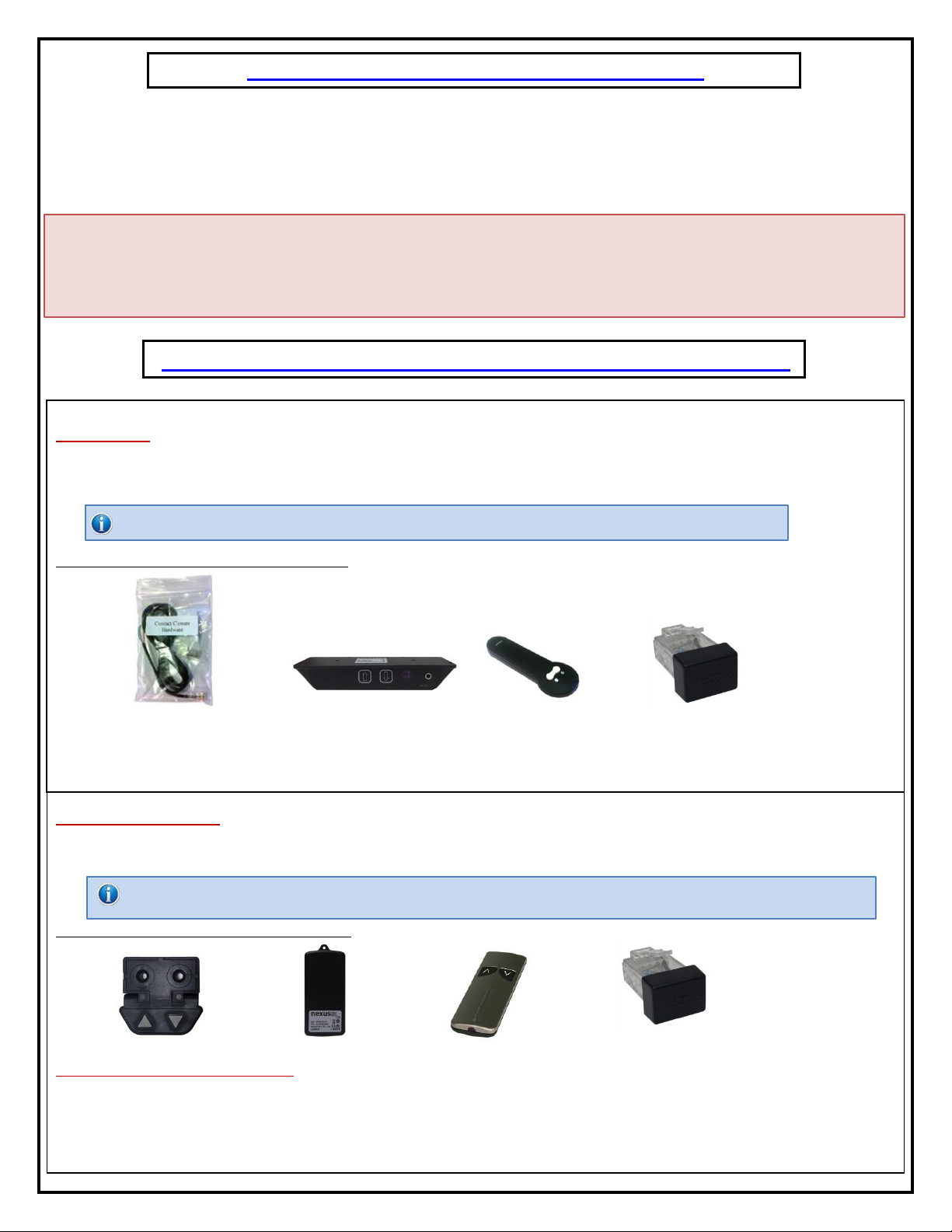
Integration by Contact Closure, and is accomplished by using the Contact Closure Hardware that is supplied with the IR Control Kit
to connect the Lift to your home control system.
Before You Begin the Installation: Identify Your Control Type
IR (Infrared) –This control option allows you to utilize a 3rd party universal style remote control to raise and lower the TV Lift.
Your universal remote will “learn” the IR codes from the provided IR Handset, which will enable you to control the lift. The universal
remote will then communicate with the “eye” located on the IR Receiver via your 3rd party emitter (or flasher). Instructions for
setting the TV Lift’s travel limit are on Page 30.
NOTE: If you are NOT planning on using a 3rd party Universal Remote, switch to the RF setup. (There is no charge for swapping)
These are the parts included with IR controls:
Contact Closure Hardware IR Receiver IR Handset Height Limit Insert
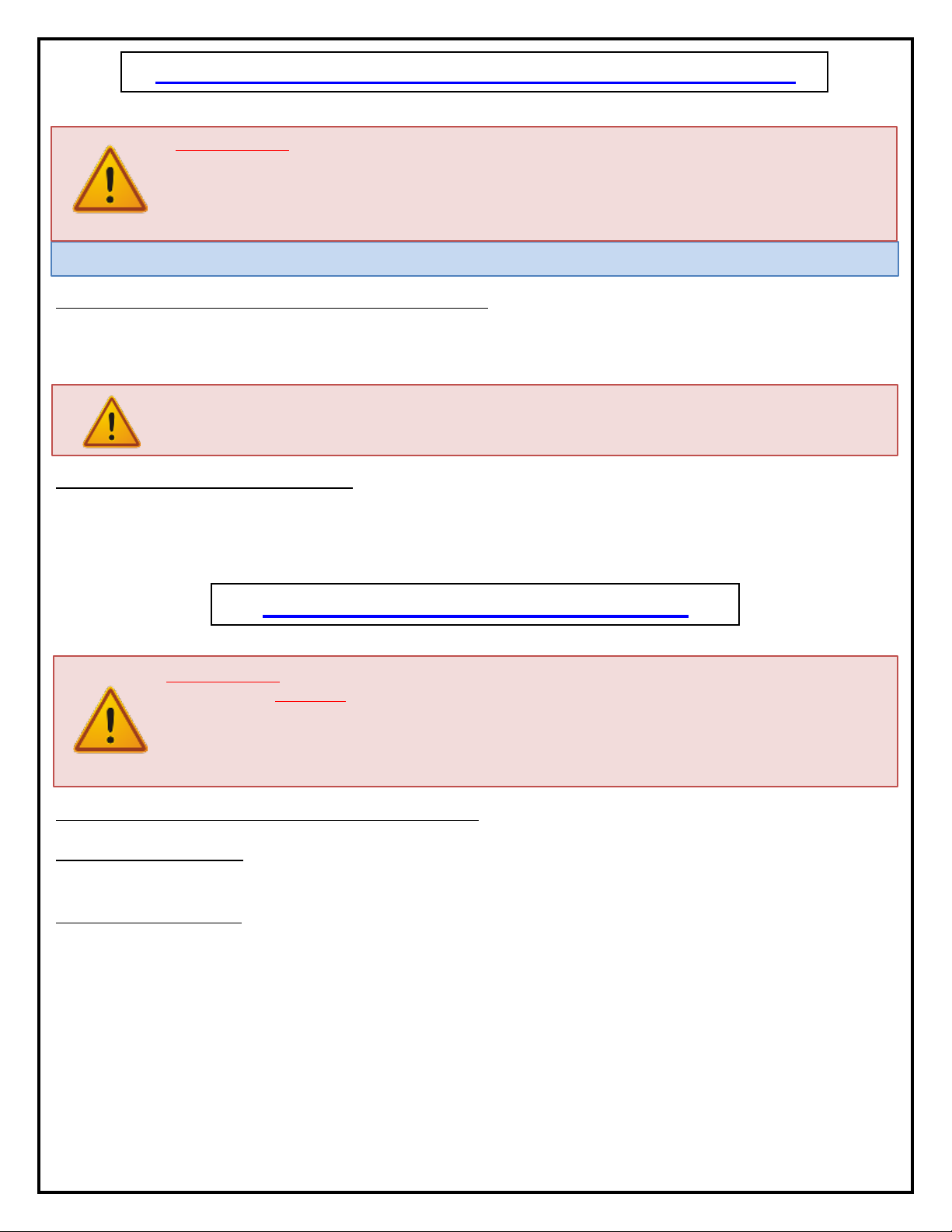
RF (Radio Frequency) - This system utilizes a wireless remote control handset that sends a radio signal to the RF Receiver. The
radio signal can go through cabinet walls and does not require line-of-sight. Instructions for setting the Lift System travel limit are on
Page 30.
TIP: Planning to integrate the TV Lift with your UNIVERSAL REMOTE CONTROL? The RF version of the Nexus 21 controls won’t do it. Switch to IR.
These are the parts included with RF controls:
Backup Switch RF Receiver RF Handset Height Limit Insert
Integration by Contact Closure –To direct-wire the TV Lift controls to a home control system (Crestron, Control 4, AMX, etc.)
you will use the Contact Closure Hardware. You won’t use any Nexus 21 receiver or handset for this type of control because you will
use the handset or control pad that comes with your home control system. Instructions for setting up the System using Contact
Closure are on “Page 31”.
6
Assembly and Mounting –Things to Think About First
SAFETY NOTICE:
- For proper support, the Lift System MUST NOT be attached to any material that is less than ¾” thick. This applies
to BOTH the back and bottom mounting points.
- The Lift Column is ONLY designed and rated for VERTICAL, NON-INVERTED USE. DO NOT MOUNT THIS LIFT
SYSTEM UPSIDE DOWN or SIDEWAYS (HORIZONTALLY)!
TIP: Inverted (drop-down) lift systems are available from Nexus 21. Contact Customer Service at (866) 500-5438.
Space requirements for the XL-75s Lift System are as follows:
Depth= TV Depth + 6.85” or a minimum of 9.75”, whichever is greater.
Height = TV Height + 2”, or a minimum of 46”, whichever is greater.
Width= TV Width + 2”
IMPORTANT NOTE: The Lift System must be mounted as high up as possible inside the cabinet, so that when
the Lift is in the fully “DOWN” position (fully retracted), the top of the TV will be just underneath the lid of the
cabinet. A 1/8” gap between the lid and the Top Plate is ideal.
Lift System height and mounting position:
The Top Support Brackets allow you to adjust the installation height of the Lift in ¼” increments if necessary. When fully
assembled in the standard configuration, the HEIGHT of the Lift will be a minimum of 45.8” up to a maximum of 53.8”
with the Top Support Brackets in the highest position. See installation dimensions diagram on following page.
About the Cabinet Lid (Cabinet Top)
SAFETY NOTICE:
WARNING! YOU MUST NOT DIRECTLY SCREW THE CABINET LID (TOP) TO THE LIFT SYSTEM!! THIS CREATES
HAZARDOUS “PINCH POINTS” AND MAY AFFECT THE OPERATION OF THE LIFT OR CAUSE DAMAGE TO THE
CABINET TOP. For floating lids, DO NOT USE SCREWS to attach the lid to the Lift System. Instead, use the
“Threaded Taper Pins”. This will keep the lid firmly in place, but will also allow it to separate from the lift system if
anything (like a finger) gets in the way when the TV lowers.
Which Lid Style Will You Use? (There are 2 Different Styles)- Hinged Lid Compatible
Floating Lid (Floating Top) –The whole top of the cabinet sits on top of the Lift System and raises/lowers with the TV.
This is the standard Installation method, using the Top Plate and Threaded Tapered Pins.
Cut-Out Floating Lid (Top) –You will “cut out” part of your cabinet top, customizing it to the size of your TV. That cut-
out lid then sits on top of the Lift System and raises/lowers with the TV. This method uses the Top Plate and Threaded
Taper Pins, but you must set up a “catch” for the cut-out lid so that when the TV lowers, the lid stops level with the rest
of your cabinet top (like a manhole cover).

7
Table of Contents
The entire Lift System consists of three major systems: the Actuation System, Cable Management System
and the TV Mounting System. This instruction manual will cover how to build, install and connect the Lift.
1) Building the Lift System
i) Lower Actuation Assembly
ii) Lower Support Assembly
iii) Installing the Lift Columns into your Cabinet
iv) Upper Actuation Assembly
a) Assembling the Actuation System
b) Assembling the Cable Management System
c) Assembling the TV Mounting System
2) Connecting the Lift
3) Mounting the TV to the Lift
4) Creating a Floating Lid
a) Threaded Tapered Pins
b) Lid Catches
5) Lift Adjustability Points
6) Dimensional Drawing
7) Reference Guide
a) Setting the Height Limit
b) Common Procedures
8) Control System Integration
8
1
2
4
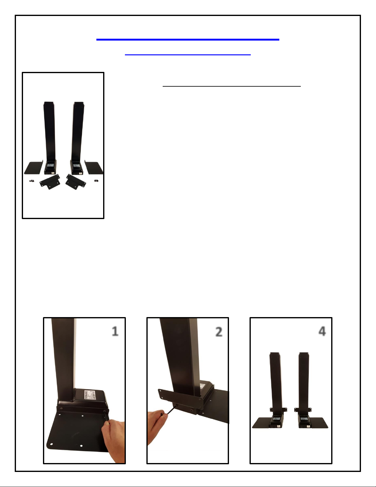
Building the Lift System
Lower Actuation Assembly
For these steps you will need the following parts:
(2) Lower Lift Columns
(2) Base Plates
(2) Lower Column Supports
(8) 6 x 10 mm BHMS Screw
Small Hex Key
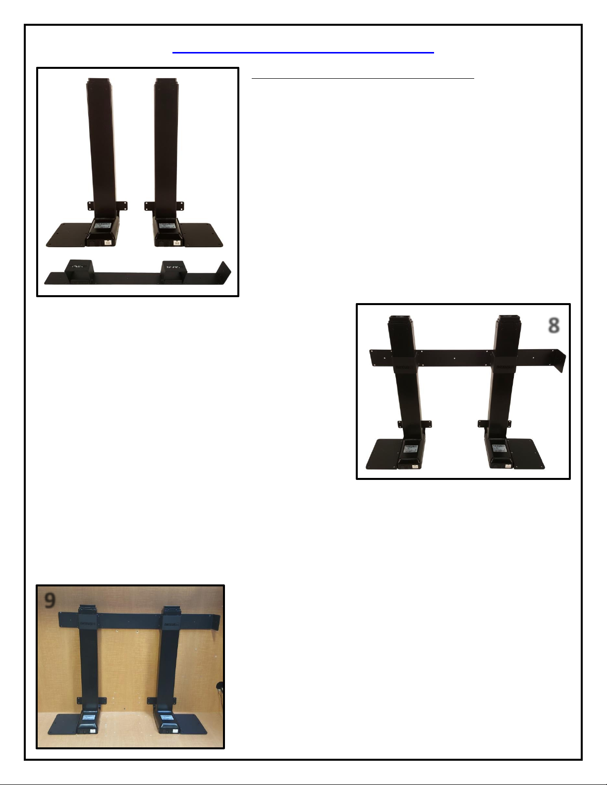
Step 1: Attach (1) Base Plate to the Lower Lift Column using (2) 6 x 10 mm BHMS screws. Refer to picture 1.
Step 2: Attached (1) Lower Column Supports to the Lower Lift Column using (2) 6 x 10 BHMS screws. Refer to picture 2.
Step 3: Repeat steps 1and 2for the second column, this time attaching the Base Plate to the alternate side.
Step 4: The Lower Actuation Assembly is now complete.
9
7
5
6
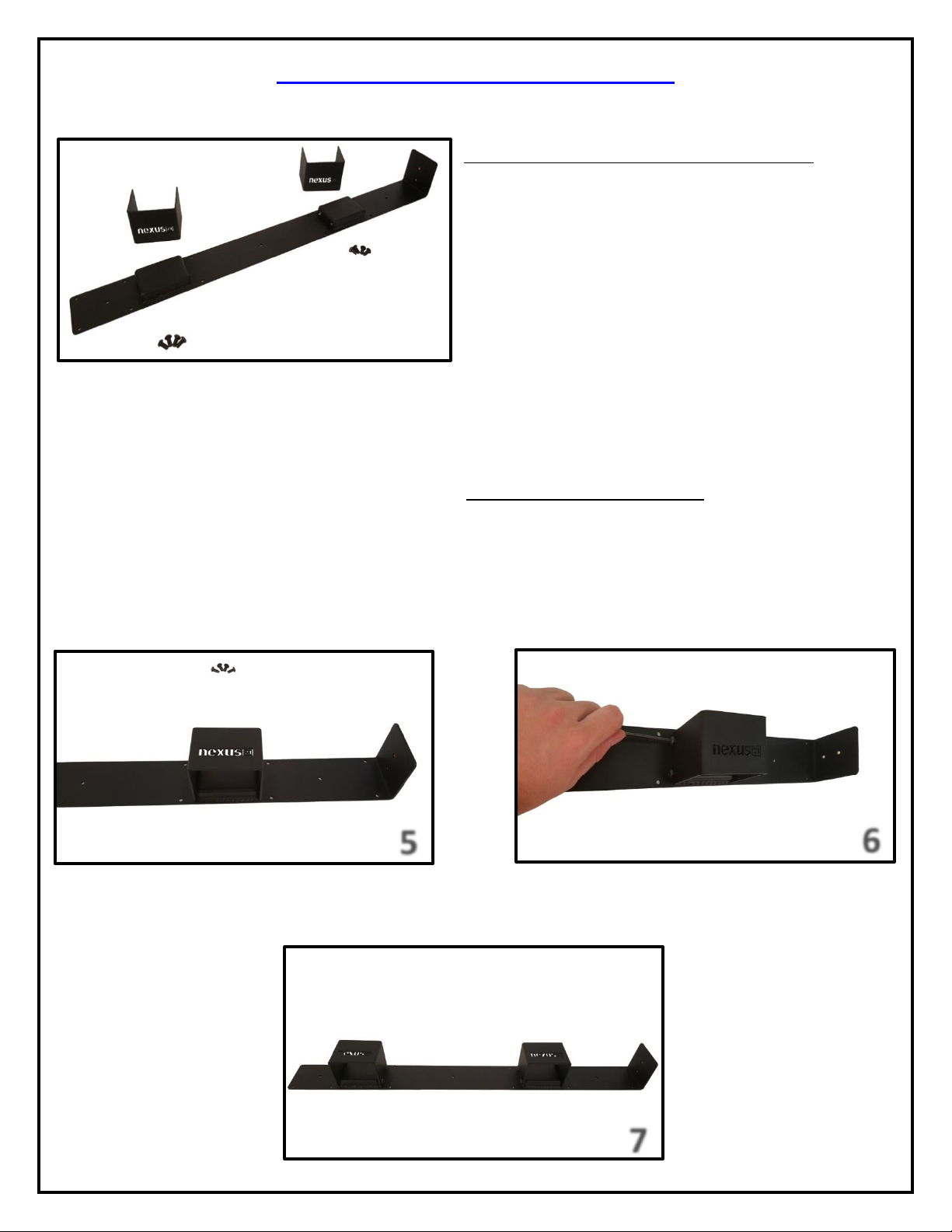
Lower Support Bracket Assembly
For these steps you will need the following parts:
(2) Lower Column Brace
Rear Support Bracket
(8) 6 x 12 mm BHMS Screws
Small Hex Key
Step 5: Place the Lower Column Braces over the raised segments of the Rear Support Bracket to match picture 5.
Step 6: Attach the (2) Lower Column Braces to the Rear Support Bracket using (8) 6x 12 mm BHMS Screws. Leave the
outer screws slightly loose for adjustment in the steps for “Assembling the Actuation System”. Refer to picture 6.
Step 7: The Lower Support Bracket Assembly is now complete.
10
Installing the Lift into your Cabinet
For these steps you will need the following parts:
Lower Actuation System
Lower Support Bracket Assembly
(35) 10 x ¾” THWS Screws
Your Cabinet
Phillips Drill Bit & Drill
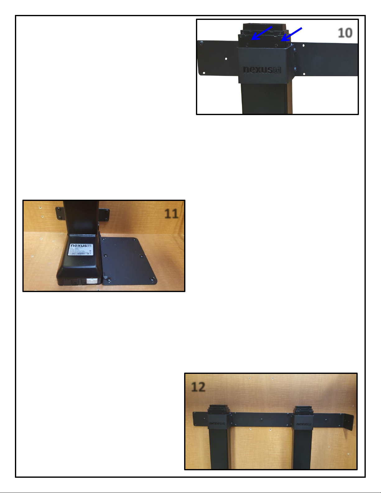
Step 8: Place the Lower Support Bracket over the Lower Actuation
System. Ensure the Nexus 21 Logo is not upside down and the 90
degree bend is on the right hand side.
Step 9: Place the Lower Actuation System with the Lower Support Bracket
into your cabinet.
8
9
11
10
Step 10: Adjust the Lower Support Bracket so that it sits
right below the 2 small circles on each of the Lift Columns.
Step 11: Center the Lift horizontally in your cabinet and
mount the Lower Column Support and Base Plate for each
column to the cabinet using (20) 10 x ¾” THWS Screws.
Step 12: Repeat Step 10 if necessary and mount the
Lower Support Bracket Assembly to the rear wall of the
cabinet using (15) 10 x ¾” THWS Screws.
11
12
12
13
14
15
Upper Actuation Assembly
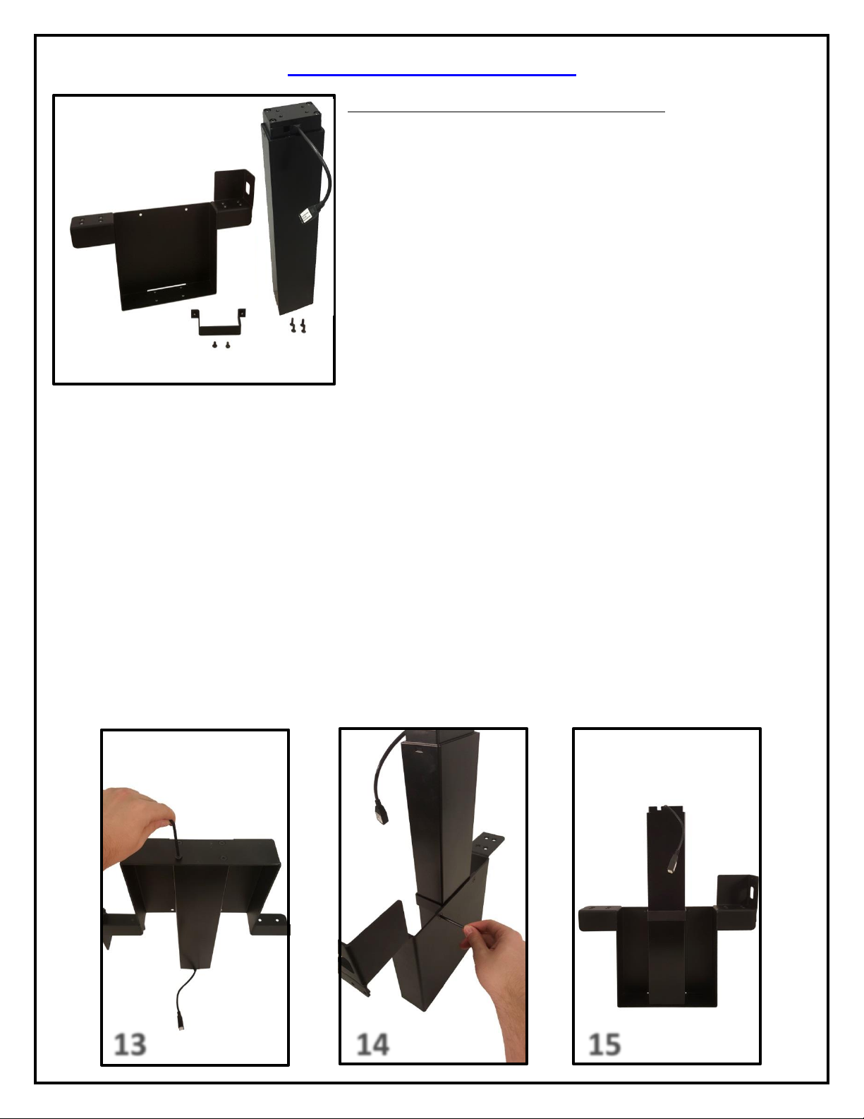
For these steps you will need the following parts:
Upper Lift Column
Center Riser Bracket
Upper Column Brace
(2) 6 x 12 FHMS Screws
(4) 6 x 20 mm FHMS
Small Hex Key
Step 13: Attach the Upper Lift Column to the Center Riser Bracket using (4) 6 x 20 mm FHMS Screws. Ensure that the
pigtail cable for the Upper Lift Column is facing the interior of the Center Riser Bracket. Refer to picture 13.
Step 14: Attach the Upper Column Brace to the Center Riser Bracket using (2) 6 x 12 mm FHMS. Refer to picture 14.
Step 15: The Upper Actuation Assembly is now complete.
13
17
16
18
Assembling the Actuation System
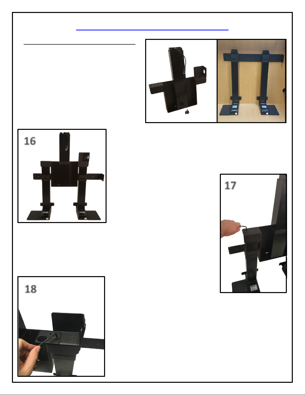
For these steps you will need the following parts:
Lower Actuation Assembly with Lower Support
Bracket already installed in the Cabinet.
Right Cable Management Bracket
Upper Actuation Assembly
Swivel Mechanism
(8) 6 x 20 mm FHMS Screws
Small Hex Key
Step 16: Place the Upper Actuation Assembly onto the Lower Actuation
Assembly. You may need to support the Upper Actuation Assembly until you
fasten it to the Lower Actuation Assembly. See photo to the left for reference.
Step 17: Fasten the left side of the Upper Actuation Assembly to the Lower Actuation
Assembly using (4) 6 x 20 FHMS Screws. See photo to the right for reference.
Step 18: Fasten the Center Riser Bracket to the Lower Actuation Assembly, then
place the Right Cable Management Bracket over the first set of holes on the
right side of the Upper Actuation Assembly and fasten them together using (2)
6 x 20 FHMS Screws leaving the screws slight loose. See photo to left for
reference.
14
20
20
19
19
19
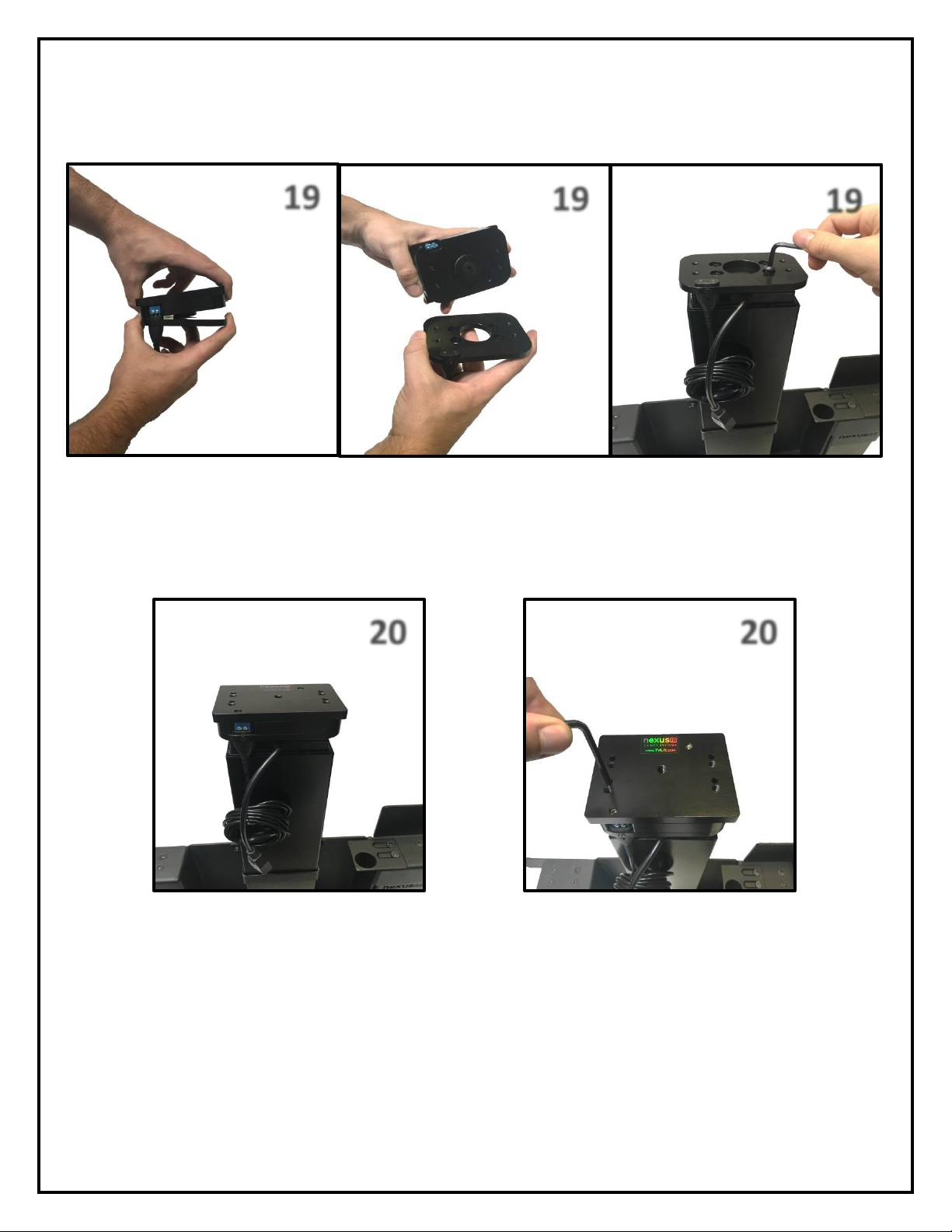
Step 19: Separate the Swivel Mechanism from the Swivel Adapter Plate and attach the Swivel Adapter Plate to the top of
the Center Lift Column using (4) 6 x 12 BHMS Screws.
Step 20: Re-Attach the Swivel Mechanism to the Swivel Adapter Plate and fasten them together by tightening the screws
in the unthreaded holes on the top of the Swivel.
15
21
22
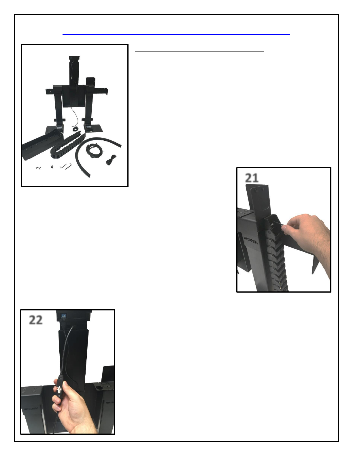
Assembling the Cable Management System
For these steps you will need the following parts:
Cable Management Track
Screen Support
Actuation System
(4) 5 x 12 mm FHMS Screws
(4) 6 x 10 mm BHMS Screws
4.5m Motor Cable
6’ Adapter Cable
Small Hex Key
3 mm Hex Key
Snakeskin Wrap
Step 21: Attach the Cable Management Track to the Center Riser Bracket using
(2) 5 x 12mm FHMS Screws.
Step 22: Connect the 4.5m Motor Cable to the Center Lift Column.
16
23
24
24
24
25
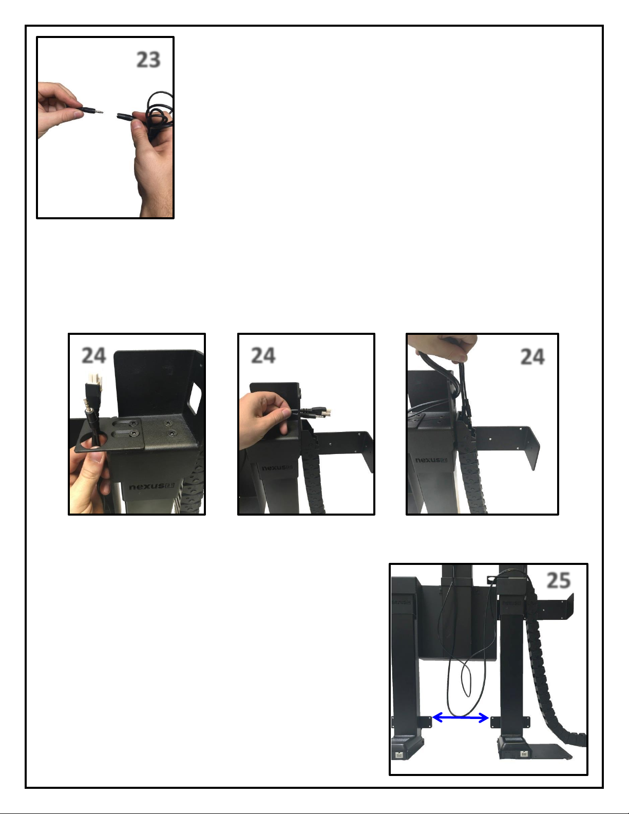
Step 23: Connect the Swivel Cable coming off of the Swivel Mechanism to the 6’ Adapter
Cable.
Step 24: Feed Both the Swivel Cable and 4.5m Motor Cable up through the Right Cable Management Bracket, through
the Slot in the Center Riser Bracket, and down through the Cable Management Track.
Step 25: Feed both the Swivel Cable and 4.5m Motor Cable through the
Cable Management Track until the cables rest equal to the Lower Support
Brackets.
17
26
27
27
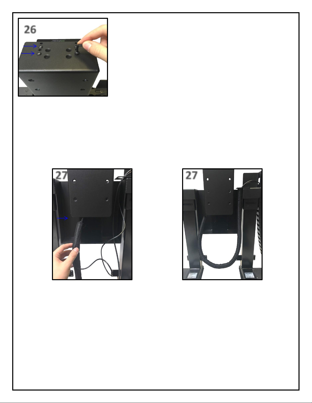
Step 26: Line up the “dotted” holes on the Screen Support Bracket with the
“threaded” holes on the Swivel Mechanism and it using (4) 6 x 10 BHMS
Screws.
Step 27: Starting from the bottom of the Screen Support Bracket, use the Snakeskin Wrap to wrap the Swivel Cable and
4.5m Motor Cable, leaving the loop between the Lower Lift Columns.
18
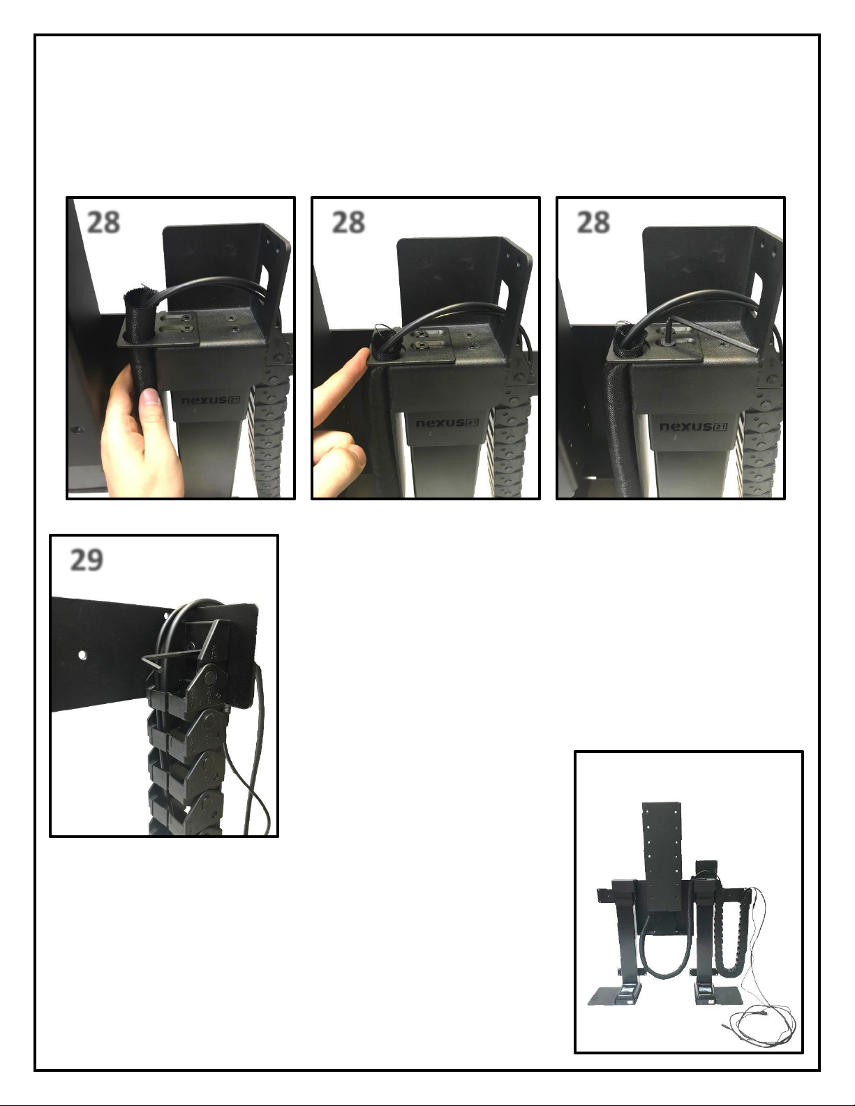
28
28
28
29
Step 28: Push the Snakeskin Wrap up through the Right Cable Management Bracket, slide Right Cable Management
Bracket to the right the pin the cables against the Center Riser Bracket, and tighten the (2) 6 x 20 FHMS Screws.
Step 29: Attach the right half of the Cable Management Track to the Rear Support
Bracket using (2) 5 x 12 mm FHMS Screws.
You have successfully installed the Cable Management System.
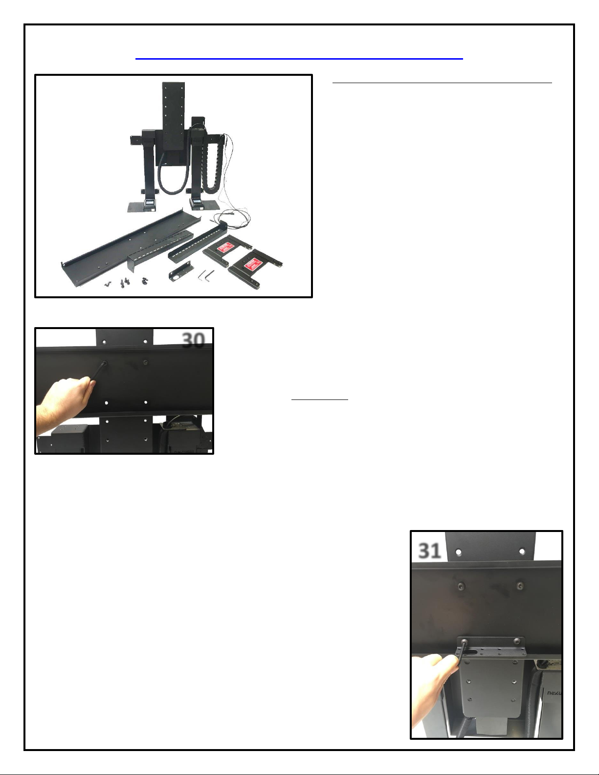
19
30
31
Assembling the TV Mounting System
For these steps you will need the following parts:
Actuation System
(2) Top Support Brackets
(2) Top Plates
Screen Back Plate
Center Cable Management Bracket
(4) 6 x 12 mm FHMS Screws
(4) 3/8” x 16 BHMS Screws
(8) 6 x 12 mm BHMS Screws
Small Hex Key
Large Hex Key
Step 30: Attach the Screen Back Plate to the Actuation Assembly using (2)
3/8” x 16 BHMS Screws. Mount the Screen Back Plate using the 4 holes
towards the middle of the Screen Support for now as adjustments will be
covered in the “Adjustments” section of the Instruction Manual on page (28).
Step 31: Using the remaining (2) holes on the Screen Back Plate, attach the Center
Cable Management Bracket using (2) 3/8” x 16 BHMS Screws. Ensure the larger
hole in the bracket is face down and to the left. See photo to right for reference.
Note: The Center Cable Management Bracket allows management of all of the TV
Cables in one bunch using the larger hole. The smaller holes act as anchors for zip
ties allowing for further cable management.
20
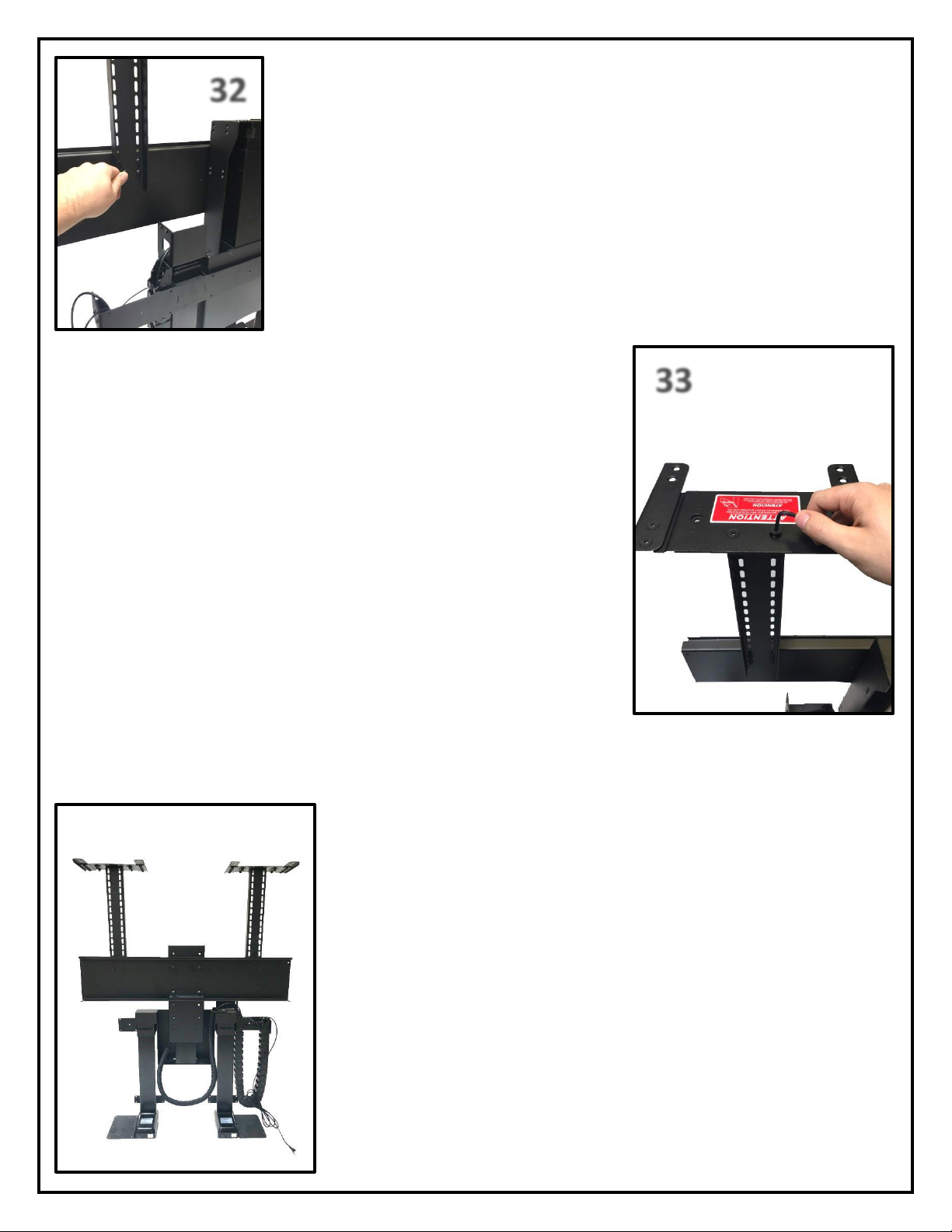
32
33
Step 32: Attach both of the Top Plates to the top of the Top Support Brackets using
(4) 6 x 12 FHMS Screws. Ensure that wings of the Top Plate are pointing towards the
front of the Lift System. See photo to the left for reference.
Step 33: Attach both of the Top Plates to the top of the Top Support Brackets
using (4) 6 x 12 FHMS Screws. Ensure that wings of the Top Plate are pointing
towards the front of the Lift System. See photo to the left for reference.
You have successfully installed the TV Mounting System.
Table of contents
Other Nexus 21 TV Mount manuals

Nexus 21
Nexus 21 L-45ens User manual

Nexus 21
Nexus 21 L-75s Installation guide

Nexus 21
Nexus 21 DL-50 User manual

Nexus 21
Nexus 21 L-50s User manual

Nexus 21
Nexus 21 ML-65 User manual

Nexus 21
Nexus 21 L-85s User manual

Nexus 21
Nexus 21 L-65 HTG User manual

Nexus 21
Nexus 21 L-45en User manual

Nexus 21
Nexus 21 DL-50b User manual

Nexus 21
Nexus 21 Transcend Pro User manual


