5 of 10 ISSUED: 05-02-06 SHEET #:202-9089-6 (2017-01-13)
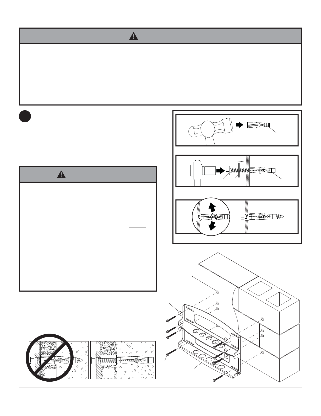
Use wall plate (A), making sure that it is level, as
a template to mark holes. The top mounting slots
should be located .43" below the desired screen
center. Use the masonry bit to drill 3/8" (10mm)
dia. holes to a minimum depth of 3" (76 mm). Insert
anchors (V) in holes flush with wall as shown (right).
Place wall plate (A) over anchors (V) and secure
with 5/16 x 3" wood screws (O) and washers (P).
1
Installation to Solid Concrete or Cinder Block Wall
A
O
P
V
• When installing Peerless wall mounts on cinder block, verify that you have a minimum of 1-3/8" of actual concrete
thickness in the hole to be used for the concrete anchors. Do not drill into mortar joints! Be sure to mount in a
solid part of the block, generally 1" minimum from the side of the block. Cinder block must meet ASTM C-90
specifications. It is suggested that a standard electric drill on slow setting is used to drill the hole instead of a
hammer drill to avoid breaking out the back of the hole when entering a void or cavity.
• Concrete must be 2000 psi density minimum. Lighter density concrete may not hold concrete anchor.
• Make sure that the supporting surface will safely support the combined load of the equipment and all attached
hardware and components.
WARNING
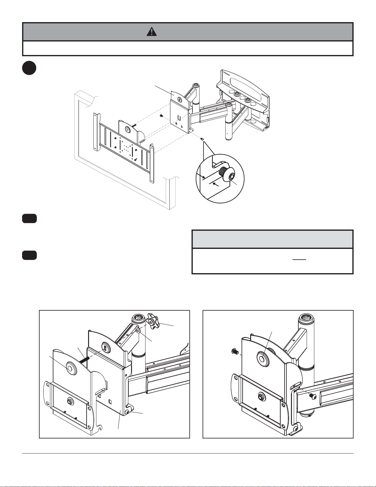
• Tighten wood screws so that wall plate is firmly
attached, but do not overtighten. Overtightening
can damage screws, greatly reducing their holding
power.
• Never tighten in excess of 80 in • lb (9 N.M.).
• Always attach concrete expansion anchors directly
to load-bearing concrete.
• Never attach concrete expansion anchors to con-
crete covered with plaster, drywall, or other finishing
material. If mounting to concrete surfaces covered
with a finishing surface is unavoidable (not evaluated
by UL), the finishing surface must be counterbored
as shown below. If plaster/drywall is thicker than
5/8", custom fasteners must be supplied by installer
(not evaluated by UL).
WARNING
1
3
2
V
Drill holes and insert anchors (V).
Place plate (A) over anchors (V) and secure with screws (Q).
Tighten all fasteners.
A
V
O
concrete
surface
CUTAWAY VIEW
INCORRECT CORRECT
wall
plate wall
plate
plaster/
drywall plaster/
drywall
concrete concrete
P