Nexus 21 Transcend Pro User manual

Transcend Pro
Installation Instructions

1

2
Contact: Sup[email protected]
Toll Free: (866) 500-5438
Phone: (480) 951-6885
Fax: (480) 951-6879
Revised: 09/14/18
Below is a parts list describing all of the items included with the Transcend Pro. You may also wish to refer to
the dimensional diagram shown on “Supplemental Page A” (at the end of this document).
Before beginning assembly and installation, please make sure that you have all items included on the list. If any
parts are missing or damaged, please contact Nexus 21. Our contact information is shown at the top of this
page.
Parts List
Screen Back Plate
Control Box
Transcend Pro
Vertical Mounting Bars
Control Box Enclosure

3
Parts List, continued
Cables
•Motor Cable 1m (2) –Black cable with white, six-pin plugs. Use this cable to connect the Actuator to the Control Box.
•Power Cable –Connects Control Box to power outlet. Three feet long.
•RF Cable (only present if you ordered the RF version of the Lift System) –Use to connect the RF Receiver to the Control
Box. Ends have RJ-45 connectors. One-foot long.
Hardware
1. Four (4) –3/8” x 3” Lag Screws w/Washers
2. Four (4) –#10 x 0.25” Phillips Screws
3. Four (4) –Zip Ties
4. Two (2) –Adhesive Rubber Bumpers
5. Four (4) –Lag Screw Covers
6. Four (4) –Lag Screw Cover Washers
7. Assorted TV Hardware
a. Four (4) –6 x 20mm PHMS
b. Four (4) –6 x 35mm PHMS
c. Four (4) –8 x 20mm PHMS
d. Four (4) –6 x 35mm PHMS
e. Four (4) –¼” Plastic Spacers
f. Eight (8) –1/8” Plastic Spacers
g. Four (4) –Steel M6 Washers

4
SAFETY INFORMATION
SEVERE PERSONAL INJURY AND PROPERTY DAMAGE CAN RESULT FROM IMPROPER INSTALLATION OR ASSEMBLY.
READ THE FOLLOWING WARNINGS BEFORE BEGINNING:
WARNINGS:
1. Do not use this product for any application other than those specified by Nexus 21.
2. Do not exceed the weight capacity. This can result in serious personal injury or damage to the equipment. It is the installer’s
responsibility to ensure that the total combined weight of all attached components does not exceed that of the maximum figure stated.
3. Follow all technical specifications and instructions during the installation.
4. Only use attachments/accessories specified by the manufacturer.
5. Close supervision is necessary when this system is being used by, or near, children, or disabled persons.
6. It is the responsibility of the installer to warn all potential users of the dangers of interfering with the mechanism during operation.
7. Read all technical instructions fully before installation and use. It is the installer’s responsibility to ensure that all documentation is
passed on the users and read fully before operation.
8. Failure to provide adequate structural strengthening, prior to installation can result in serious personal injury or damage to the
equipment. It is the installer’s responsibility to ensure the structure to which the Mount System is affixed can support four times the
weight of the system.
9. Risk of electric shock. Do not attempt to open the Control Box.
10. To reduce risk of fire or electric shock, do not expose parts to rain or other liquids.
11. Protect the power cord from being walked on or pinched.
12. Keep all documentation.
13. Heed all warnings.
14. Clean only with a dry cloth.
15. Refer all service questions to Nexus 21 if the system does not operate normally.
Nexus 21 disclaims any liability for modifications, improper installations, or installations over the specified weight range. Nexus 21 will not be liable for any damages
arising out of the use of, or inability to use, Nexus 21 products. Nexus 21 bears no responsibility for incidental or consequential damages. This includes, but is not limited
to, any labor charges for the servicing of Nexus 21 products performed by anyone other than Nexus 21.
Nexus 21 intends to make this and all documentation as accurate as possible. However, Nexus 21 makes no claim that the information contained herein covers all
details, conditions or variations, nor does it provide for every possible contingency in connection with the installation or use of this product. The information contained
in this document is subject to change without prior notice or obligation of any kind. Nexus 21 makes no representation of warranty, expressed or implied, regarding the
information contained herein. Nexus 21 assumes no responsibility for accuracy, completeness or sufficiency of the information contained in this document.

5
Types of Controls for Nexus 21 Systems
All Nexus 21 Systems come standard with a wireless remote control and receiver. We offer a choice of two different types of remotes:
IR and RF (both of which are explained in detail below). Our standard control type is RF, so unless you specifically requested the IR
version when you made your purchase, you probably received the RF controls with this Mount System. The method of installation for
each type of remote control is slightly different, so you should now identify which type of remote you have by reading below, and
then follow the instructions for that type of remote.
NOTE: If you will be using the Mount with a home control system (like the ones made by companies such as Crestron or Control 4)
the most common form of control is to WIRE IT DIRECTLY to the relays of your home control system. This direct-wire method is called
Integration by Contact Closure, and is accomplished by using the Contact Closure Hardware that is supplied with the IR Control Kit to
connect the Mount to your home control system.
Before You Begin the Installation: Identify Your Control Type
IR (Infrared) –This control option allows you to utilize a 3rd party universal style remote control to raise and lower the Mount.
Your universal remote will “learn” the IR codes from the provided IR Handset, which will enable you to control the mount. The
universal remote will then communicate with the “eye” located on the IR Receiver via your 3rd party emitter (or flasher). Instructions
for setting the Mount’s travel limit are on Page 19.
NOTE: If you are NOT planning on using a 3rd party Universal Remote, switch to the RF setup. (There is no charge for swapping)
These are the parts included with IR controls:
Contact Closure Hardware IR Receiver IR Handset Height Limit Insert
RF (Radio Frequency) - This system utilizes a wireless remote control handset that sends a radio signal to the RF Receiver. The
radio signal can go through cabinet walls and does not require line-of-sight. Instructions for setting the Mount System travel limit are
on Page 19.
TIP: Planning to integrate the Mount with your UNIVERSAL REMOTE CONTROL? The RF version of the Nexus 21 controls won’t do it. Switch to IR.
These are the parts included with RF controls:
Backup Switch RF Receiver RF Handset Height Limit Insert
Integration by Contact Closure –To direct-wire the Mount controls to a home control system (Crestron, Control 4, AMX, etc.)
you will use the Contact Closure Hardware. You won’t use any Nexus 21 receiver or handset for this type of control because you will
use the handset or control pad that comes with your home control system. Instructions for setting up the System using Contact
Closure are on “Page 22”.

6
Table of Contents
1. Connecting the Mount
2. Assembling the Mount
3. Installing the Mount
4. Attaching the TV to the Mount
5. TV Level Adjustment
6. How to Set the Tilt
7. How to Set a Lower Limit
8. Cable Management Information
9. Maintenance & Contact Closure Information

7
Connecting the Mount
For these steps you will need the
following parts:
•Transcend Pro Mount
•Control Box
•(2) Motor Cables
•Power Cord
•Wired Backup Switch
•CSI Control Kit or RF Control Kit
Step 2: Connect the Motor Cables to Ports 1 & 2 which are
located on the front and back face of the Control Box.
Step 1: Connect the Motor Cables to the Pigtail on each
Actuator for the Transcend Pro.

8
Step 5: Press and hold the Down button on the Wired Backup Switch and
run the Actuators to their lowest position.
Step 6: Once the Actuators stop, release the Down button then press and
hold it again until you hear a click from both Actuators. This will initialize
them so they start and stop at the same point.
UP
DOWN
Step 4: Connect the Power Cable to Port AC on
the Control Box and connect the other end to a
Wall Outlet.
Step 3: If the system came with RF Controls, connect the Wired Backup Switch and RF Receiver to Ports A1
& A2 on the Control Box.
If your system came with the CSI Kit, connect just the IR Receiver to Port A1 on the Control Box.
CSI Kit
RF Kit

9
Assembling the Mount
For these steps you will need the following parts:
•Swivel Pivot Bolt
•Swivel Pivot Nut
•(2) Swivel Pivot Washers
•(2) 5 x 35mm BHMS Screws
•(4) #10 x 0.25” Phillips Screws
Swivel Pivot Nut
Swivel Pivot Bolt
Step 7: Attach the Screen Back Plate to the Mount using the
Swivel Pivot Bolt, Swivel Pivot Nut, and (2) Washers using the
diagram shown to the right. Ensure the thinner washer
remains on top.
Step 8: Adjust the Swivel Tension, by loosening or tightening the
Swivel Pivot Nut while holding the head of the Swivel Pivot Bolt
with a Wrench.
10
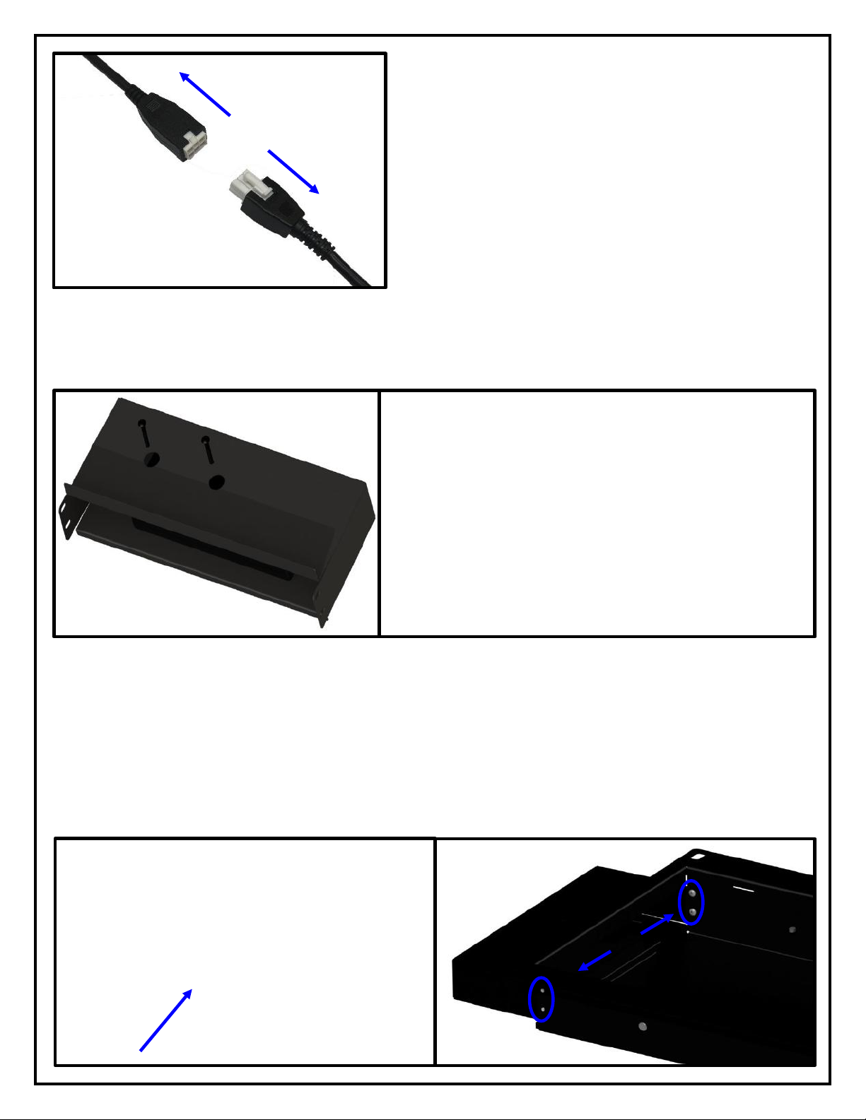
Step 9: Disconnect the Motor Cables from the Actuators.
Step 11: Place the Enclosure into the top slot of the Transcend Pro and Fasten it to the recess box using (4)
Phillips Screws.
Step 10: Place the Control Box with all of its connections into the Control Box enclosure and fasten it to the
enclosure using (2) BHMS Screws.

11
Step 14: Reconnect the Motor Cables to each Actuator.
Step 15: Press the Up button to run the mount to the
top most position then disconnect it from power.
Step 12: Remove the Cable Management Covers on
the interior sides of the Recess Box.
Step 13: Place all the cables into their respective
areas and replace the Cable Management Covers.

12
Installing the Mount
For these steps you will need the following parts:
•Transcend Pro
•(4) Lag Bolts
•(4) Lag Bolt Cover Washers
•(4) Washers
•(4) Lag Bolt Covers
Step 16: Remove the Knock Out for your power on
the bottom of the Recess Box.
Note:
At this point make sure the necessary power
supply is ran to the cutout in the wall for the mount,
TV, and any other components.
Step 17: Measure Your Shelf Depth [D], if you do not have a Shelf or Mantel proceed to the next step.
Step 17a:
Using shelf depth [D], locate the cell in (Table 1) to determine the [H] (Minimum Clearance)
Step 17b:
Using the shelf depth [D] locate the cell in (Table 2) to determine the [H] (Minimum Clearance)
Note: The Transcend Pro must always be able to lower its full travel with no obstructions.
Note: Mocking the TV up on the mount prior to installation will allow you to determine where the TV will rest
relative to the bottom of the mount. This will ensure the requirements for Table 2 are met and the TV does not
collide with the top of the shelf during downward travel.

13
Step 20: Mark the Screw locations on the wall and Drill Pilot Holes for each
Screw Location.
Note:
Ensure the Pilot Hole is centered within the slot. This will allow minor
adjustment for the position of the mount if needed.
Step 18: Place the top end of the Transcend Pro into the cutout in the
wall, push it up, then push the bottom half of the mount into place.
Note:
Be sure to pull the necessary power supply up to the knockout in
the bottom of the Recess Box.
Step 19: Connect power cord for the Control Box to your power supply or
outlet.

14
Step 22: Level the Mount off of the Screen Back Plate, ensure it is level relative to the mantel or floor, then
completely fasten Lag Bolts.
Important Note:
If the mount is unlevel, use the Slotted Holes for the Lag Bolts to adjust its position. If the
mount is still unlevel, the cutout may need to be expanded. Finer adjustments for the level of the TV can
be made separately and are covered later in Adjustments section of this Instruction Manual.
Step 23: Place the (4) Lag Bolt Covers over each Lag Bolt Cover Washer
when finished.
Step 21: Partially fasten the Mount to the Wall using (4) Lag Bolts,
(4) Washers, and (4) Lag Bolt Cover Washers.

15
Attaching the TV to the Mount
For these steps you will need the following parts:
•Vertical Mounting Bars
•Large Assorted Hardware Pack
Step 24: Attach the Vertical Mounting Bars as high as
possible on the Back of the TV
Note:
This will ensure the mount has the most
possible downward travel and is fully concealed when
in the Top Position.
Step 25: Retract the spring-loaded Screen Locks on the Vertical Mounting
Bars to their down and locked positions.

16
Step 28: Test run the Mount to ensure the lowest
position does not interfere with the shelf or mantel
below it.
Step 27: Hang and center the TV on the Screen Back Plate, then release the spring-loaded Screen Locks to
secure the TV in place.
Step 26: Press the Down button on the Wired Backup Switch to lower the
Mount, press the Up button to stop it once it reaches the out most
position.

17
TV Level Adjustment
Step 1: Disengage the Spring-Loaded Screen Lock.
Step 2: Loosen or Tighten the Bolt on the Top of either
Vertical Mounting Bar, to raise of lower that side of the TV.
Note: Maximum adjustment of +/- 0.5 Degrees.
Step 3: Re-engage the Spring-Loaded Screen Lock.
Step 4: Test run the Mount to ensure the position is set
correctly.
1
2
3

18
How to Set the Tilt
The has +/- 1 degree of Tilt in the Top Position, and +1/-2 Degrees in the Bottom and Out Positions. Below are
the steps on how to set the Tilt for each position of the mount.
Step 3: To increase the Tilt, loosen the Lock Nut on the
Screw and loosen the Screw from the Screen Back Plate.
Note: There is only +/- 1 degree of Tilt in this position.
Step 2: Fasten each Screw into the Pem Nuts located
on the left and right side of the Screen Back Plate.
Step 1: Fasten the Lock Nuts to each of the Screws
completely. Fasten the Lock Nuts to each of the Screws
completely.
Pem Nut Location
Step 1: Tighten the Bolt shown in the figure below to adjust the bottom tilt +1/-2 degrees.
Top Tilt Adjustment
Bottom Tilt Adjustment

19
How to Set a Lower Limit
Only the Lower Limit can be set on the Transcend Pro, however it must be able to fully travel with no
obstructions below it. This is because the Mount resets in the lowest position and will be unable to reset if it is
obstructed.
To set a Lower Limit follow the steps listed below:
1. Press the DOWN button on the Wired Backup Switch or Remote Control.
2. Once the Mount reaches your desired position, press the UP button to STOP the Mount.
3. Plug the Height Limit Insert into Port A2 on the Control Box if you are using IR Controls. If you are using RF
Controls, plug the Height Limit Insert into the available RJ45 Port on the RF Receiver.
OR
Table of contents
Other Nexus 21 TV Mount manuals

Nexus 21
Nexus 21 DL-50b User manual

Nexus 21
Nexus 21 L-50s User manual

Nexus 21
Nexus 21 L-65 HTG User manual

Nexus 21
Nexus 21 L-45en User manual

Nexus 21
Nexus 21 L-75s Installation guide

Nexus 21
Nexus 21 L-85s User manual

Nexus 21
Nexus 21 L-45ens User manual

Nexus 21
Nexus 21 DL-50 User manual

Nexus 21
Nexus 21 ML-65 User manual

Nexus 21
Nexus 21 XL-75s User manual


