INTRODUCTION
We recommended you read this manual before attempting installation in
order to fully utilise the panels functions in your application.
An understanding of the manual will lead to a quicker, easier installation of
the system.
The Nexus 8 has been designed to simplify the installation process, making
wiring easier and subsequently quicker. Individual tampers for each zone
have replaced a single global tamper and each zone now has a 12v auxiliary
power supply. A detachable gear tray aids wiring and protects the printed
circuit board from damage.
PLANNING THE INSTALLATION
• To maximise the system’s effectiveness pre-plan the installation.
• Consider the layout of the building and each of its access points.
• Use the pre-programmed system mode which is best suited to the
building. (See programming guide p.18)
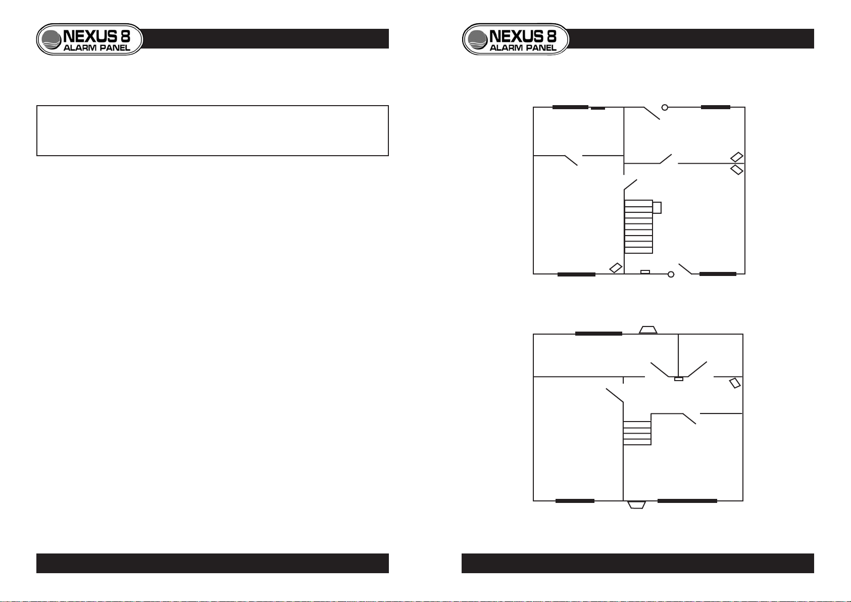
A common layout is shown below, using zone preset option 91 (see
programming guide for details of how to set zone preset options p.18). This
option has been chosen as it best suits the installation, taking layout and user
requirements into account. As the majority of forced entry’s are made through
the front and back doors, they have been fitted with contacts. PIRs have
been fitted guarding against entry through windows, with the exception of
zone 4 which is protected by a vibration detector, making the room suitable
for housing pets. Both zones six and seven are omitted in part sets 1 and 2,
giving access to bedrooms during night setting. The panic attack is located
upstairs close to each of the bedrooms as most burglaries take place at night.
ZONE PRESET OPTION 91 (PANEL DEFAULT)
3
INSTALLATION EXAMPLE
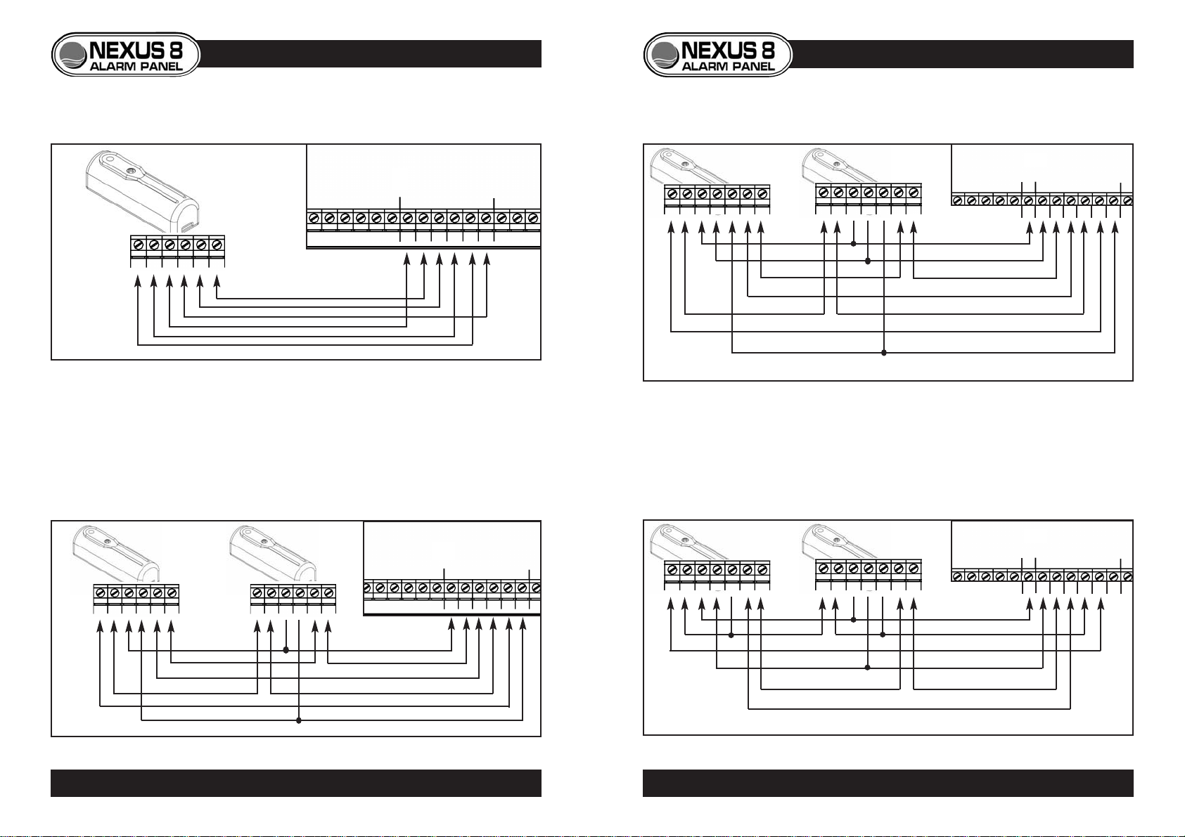
DOOR
CONTACT
DOOR
CONTACT
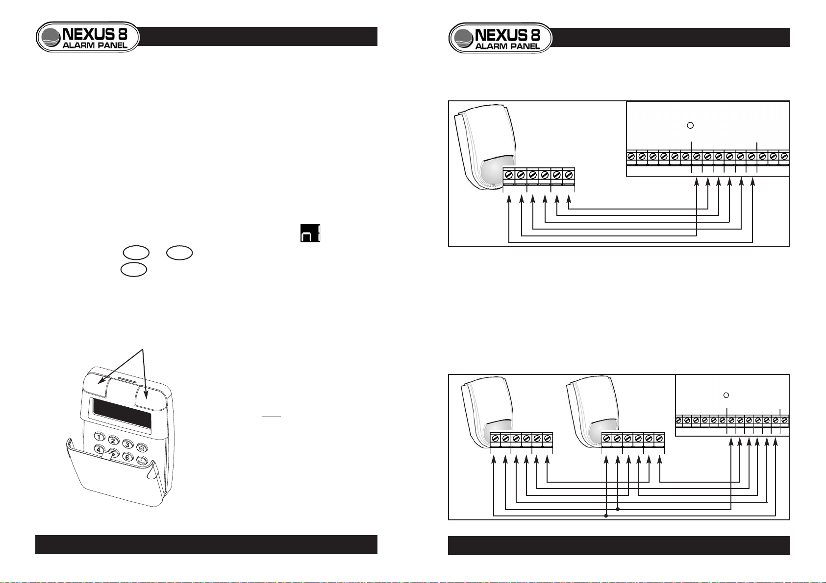
P.I.R.
P.I.R.
P.I.R. KEYPAD
P.I.R.
VIBRATION
DETECTOR
DUMMY
BELL BOX
PANIC
ATTACK
BELL BOX
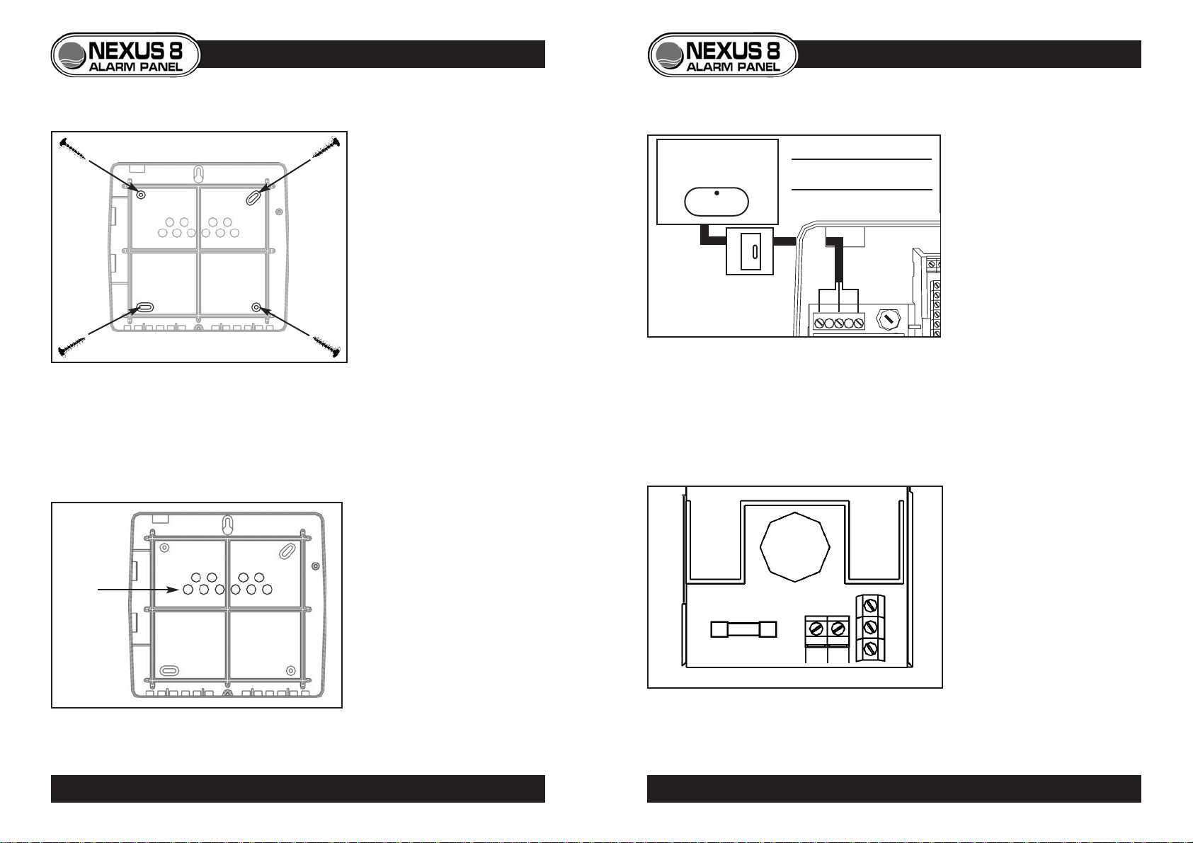
CONTROL PANEL
(UNDER STAIRS)
(zone 2)
(zone 3)
(zone 6)
(zone 1)
(zone 8) (zone 7)
(zone 5)
(zone 4)
Ground
Floor
First
Floor
2PLANNING THE INSTALLATION
© Lynteck Ltd. 1998 LY68-030-68