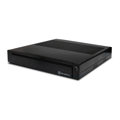
Nexxt Solutions Professional Series User manual

ProfessionalSeries
Fully assembled
dual hinged wallmount enclosure
NPC-P12U65B
NPC-P15U65B
NPC-P18U65B
NPC-P6U65B
NPC-P9U65B

User manual
Warning: the wall structure must be capable of supporting the total weight, which
includes the cabinet plus its maximum static load. Otherwise, the wall structure must be
reinforced.
Caution: this product is heavy, at least two qualified people should perform the
assembly procedure. Personal injury and/or property damage can result from dropping
or mishandling the enclosure.
Do not exceed the recommended load capacity per rack, and the maximum weight
supported by the enclosure, as indicated by the manufacturer’s specifications. Failure
to comply will void the warranty of this product.
For safety, use proper equipment and tools during the assembly to prevent personal
injury and to avoid damaging its parts.
FALLING EQUIPMENT HAZARD: ensure that the cabinet is properly anchored to the
wall prior to loading equipment inside.
Carefully read and follow the safety
instructions included in this manual before
assembling and using the cabinet.
FAILURE TO FOLLOW THESE INSTRUCTIONS CAN LEAD TO
SERIOUS INJURY, DEATH, OR DAMAGE TO YOUR EQUIPMENT
IMPORTANT SAFETY INFORMATION
Main features
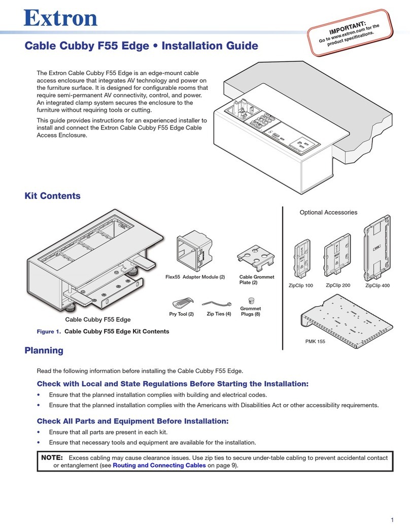
• No assembly required, the system ships ready to mount to a wall
• Hinged cabinet opens away from the wall for ease of equipment Installation
• Accessibility from both the front and rear for simplified diagnostic, maintenance and
service of devices housed inside the enclosure
• Pivoting frame with locking mechanism swings out 180 degrees
• Features a fully welded frame construction reinforced with heavy gauge steel, specially
designed to support heavy equipment
• 132lb (60kg) maximum static load capacity and 66lb (30kg) maximum dynamic load
capacity
Caution: for dynamic weight applications, do not open the door if the cabinet load
rating is equivalent to or greater than 132lb (60kg)
• Toolless, reversible glass door installation
• Solid and removable side panels
• Standard square-punched mounting rails for faster equipment loading
• The front door can turn 180 degrees
• U-rack units are numbered front and back for easy equipment installation
• Finished surface to prevent damage caused by rust and other external factors
• High-grade, cold-rolled steel structure with a 5-year warranty
For support and to find out more about our complete line of products and solutions,
we invite you to visit us at nexxtsolutions.com.
ELECTRICAL
SHOCK
HAZARD.
DANGER All parts of the unit must be properly grounded to the frame
of the enclosure and connected to the Common Bonding
Network (CBN) of your facility.
1. Introduction
Thank you for purchasing the welded swing frame wallmount cabinet system from
Nexxt Solutions. This enclosure is made up of heavy-gauge steel and a sturdy mounting
frame. It also features a tempered-glass front door, with lockable access to keep
network gear and communication cabling safe and properly organized. Each enclosure
supports optional fans to ensure optimum ventilation inside the unit.
Available with 6, 9, 12, 15 and 18 rack spaces, these enclosures are designed for
housing patch panels, switches, PDUs and any standard 19in equipment where floor
space is at a premium. Flexible and versatile, our cabinets come fully assembled for
rapid deployment, offering a practical and cost-effective solution for applications
requiring protection, structural integrity and cable management capabilities.
1 2

2.Preliminary steps
• Prior to installing this product, you must read all instructions thoroughly.
• Keep these instructions handy in an easily accessible location for future reference.
• A clean, flat, level, protected floor area should be provided for the enclosure assembly
to prevent damage to parts.
• The installers may need to have the following items and tools available to assemble
and install the rack. They are not included in the box.
3. Product overview and components
Upon opening the box, inspect the contents to ensure that all the items listed
below are included:
1. Phillips screwdriver
2. Power drill with the following:
M6 bit
M8 hexagonal-head tip
3. Hex to square socket adaptor
4. Pair of gloves
5. Long-nose pliers
6. Cleaning towel
7. 3mx2m mat or padded surface
1 2 3 4 5 6
Part ID Item Quantity Image
Wallmount enclosure
Tempered glass front door
1
Pre-installed
White plastic bushing
M6 washer
M6x12mm phillips head screw
M6 cage nut
M6 wall anchor bolt
Set of keys
Drilling template
User manual
6U 9U 12U 15U 18U
6U 9U 12U 15U 18U
12
12
12
4
24
24
24
6
Pre-installed
Hardware mounting kit
1
3
4
5
6
7
8
9
10
2
3 4
1 set (door and
pivoting frame
mechanism)
1
1

4. Wall-mounting procedure
3
4
Preliminary steps
1. On the rear wall of the enclosure are 4 mounting holes.
2. Choose a mounting position and with the supplied template,
proceed to mark the locations of the holes on the wall surface.
3. Drill a pilot hole in the center of each mark using the hand-held
tool.
Note: prior to drilling the holes, confirm that the markings are
accurately leveled to avoid destabilizing the entire structure.
4. Drive the anchors and bolts into the predrilled holes on the wall.
Leave a small clearance (¼in) between the surface and the bolt
heads to allow hanging the enclosure into position.
1
2
Phase Image Mounting step
Warning
Confirm that the wall is strong enough to support the weight of the enclosure
with all the loads. Failure to follow these procedures may result in personal injury
damage to the equipment.
Mounting the enclosure to the wall
1. Once the bolts are properly secured, align the enclosure frame
with the anchor bolts installed.
2. Make sure that the pivoting frame is locked prior to hanging the
unit against the wall.
3. Carefully slide the enclosure into its final mounting position.
Securing the enclosure
1. Unlock the pivoting frame and swing the body of the enclosure out
to expose the back of the structure.
2. With the enclosure already installed in place, fully tighten the
mounting bolts from the inside to firmly secure the unit.
Ground connection
1. Connect the first grounding cable to the door using the provided
hardware.
2. Likewise, connect the second grounding cable to the side panel
using the hardware provided.
3. Using the self-tapping screw bind both grounding cables to the
closest mounting hole on the right side horizontal beam.
5 6

4. Then, connect the grounding cable to the left side panel on the
rear section of the cabinet.
5. Using the self-tapping screw, bind the grounding cable to the
closest mounting hole on the left side horizontal beam.
Note: fully-tighten the screws only after all the screws have been
inserted.
Notes
7 8

NotesNotes
9 10

Other manuals for Professional Series
3
This manual suits for next models
5
Table of contents
