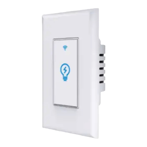
Nexxt Solutions NHE-S100 User manual

WARRANTY
nexxtsolutions.com/warranty
YEAR
2
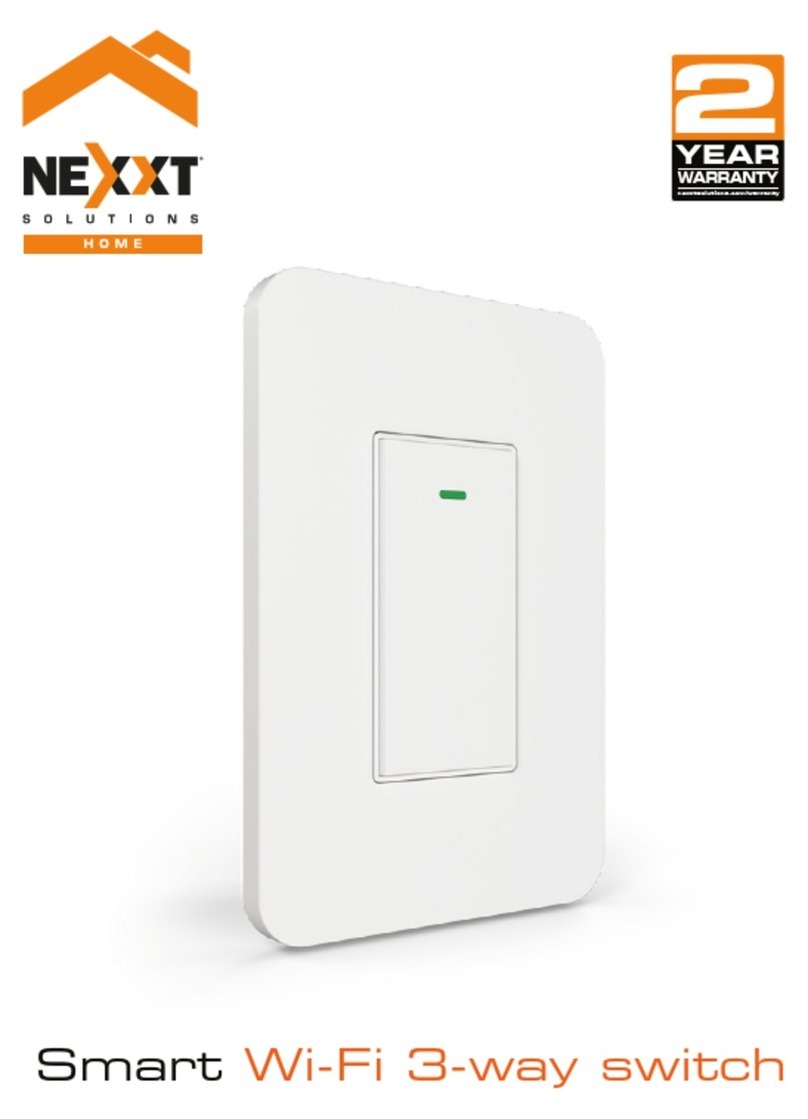
Smart Wi-Fi light switch
Single pole

English
User guide
Thank you for purchasing the Smart Wi-Fi light switch
from Nexxt Solutions. We are excited for being a part of
making your life easier, safer and bringing peace of mind
inside and outside your home.
Package content
- Light switch (1)
- Wall plate (1)
- Plate screw (2)
- Wire nut (4)
- Quick start guide (1)
Safety information
Precautions
Please read and understand this entire manual before
attempting to assemble, install and operate this smart
electrical xture.
This product requires replacing the existing switch through
a hard-wiring process.
This smart electrical xture requires 110-220-volt AC.
This device has been tested by the manufacturer according
to all international electrical standards. However, every
state has dierent standards and rules for installing
electrical cabling and equipment in a home.
Please check with your local and state laws prior to using
this device.
Improper installation of product may cause electrical injury
to an individual.
Installation of this product must be performed by a
qualied electrician or a certied electrical technician. Do
not attempt to perform installation if you are not familiar
with hardwired electrical connections.
Improper installation can lead to loss of warranty.
Nexxt Solutions assumes no liability for the improper
installation of this product.

Product overview
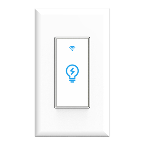
1. Smart switch indicator light:
displays the status of the
wireless connection and
switch.
2. Switch: use it to manually
toggle the device on and o
3. Face plate
Red
Red
Green
Red
Red
Blinks fast
Blinks slowly
(once every
3 seconds)
Solid
Solid
O
Ready for pairing
(default mode only)
Ready for connection (AP
mode only)
Indicates that pairing is successful
and that the light switch status is ON
Indicates that the light switch is OFF
No internet connection available
LED light Status Description
Turn power o at the circuit breaker or fuse.
Use only when it’s installed with a residual current device (RCD) or
current leakage protector at home.
WARNING: For safety, this light switch must be
properly grounded.
WARNING: To avoid risk of electric shock or
electrocution, install the light switch away from
any water source.
WARNING: This light switch supports single pole
circuit only. It is not compatible with 3-way
(multi-location control) connection circuit.
WARNING: A neutral wire is needed to power the
light switch.
WARNING: This device is single band and will
only work with 2.4GHz Wi-Fi routers.
1
2
3

4. Load wire
5. Live wire
6. Neutral wire
7. Ground wire
GROUND
LOAD
LINE
NEUTRAL
4
5 6 7
Initial inspection
Before installing the electrical xture, ensure that all parts
are included in the package. If any part is missing or
damaged, do not attempt to assemble, install, or operate
this product.
Estimated installation time: about 30 minutes.
Tools that may be required but are not included for
installation
1. Phillips screwdriver
2. Flathead screwdriver
3. Pliers
4. Wire strippers/cutters
5. Circuit tester
6. Work gloves
7. Electrical tape
8. Safety goggles
1 2
3 4
5 6
7 8

Hardware installation
IMPORTANT
For safety, properly ground the switch
Always follow the code standards when installing wired
connections.
Step 1
Shut power off at the breaker
Find the breaker that controls the circuit for the junction
box where the smart light switch will be installed. Turn it to
the OFF position.
Place tape over the circuit breaker switch and verify that
power is o.
Note: you can use the circuit tester at this point to verity
that power is cut o.
ON OFF
ON OFF
ON OFF
Step 2
Remove the original switch from the wall box
Identify the Line, Load, Neutral and Ground wires.
Note: If the existing switch has two jacks, you may nd 5
wires or more. Identify the neutral, line, load and ground
wires. This smart switch only needs to use these 4 wires,
since it does not require the connection of additional
circuits.
Ground
Line
Load
Switch
(Line/Load)
Neutral

Note: a single bare copper wire is also used to
represent the ground wire in existing electrical installations.
Europe/Australia color code standard:
Blue is for neutral, brown represents the live and load
wires, and the yellow/green cable is for grounding.
Note: a single bare copper wire is also used to
represent the ground wire in existing electrical installations.
Step 3
Label your wires
Mark the corresponding cables before removing the
existing light switch.
Always follow code standards when installing wired
connections.
Note: All the images are for reference only and therefore
they must not be used as a standard.
North American color code standard:
White is for neutral, black represents the live and load
wires, and the yellow/green cable is for grounding.
GROUND
LINE LOAD
Line
Load
NEUTRAL
GROUND
LINE LOAD
Line
Load
NEUTRAL

Gently push all the excess wiring into the junction box.
Note: make sure all the wires are positioned in an
organized manner and away from the edges of the light
switch and the junction box, to avoid pinching any of the
cables, prior to completing the process.
Proceed to align the smart switch to the base on the
junction box, so that it is oriented correctly.
Insert the two center screws through the switch and into
the mounting hole on the junction box. Secure the switch
to the base of the box.
To complete installation, gently push the faceplate into the
box until it snaps in place.
For safety, properly ground the switch
Always follow the code standards when installing wired
connections.
Step 4
Mount the smart switch
- Using the correct polarity, match each wire from the smart
switch with those coming from the junction box.
- Connect the wire ends of each pair into the wire nut, then
twist each nut full turns until the connection is fully
secured. Repeat this step for each cable assembly.
Note: make sure that there is no wire exposed.
Make sure to follow the wiring conguration:
1) Neutral wire (white) on the smart switch to neutral on
junction box.
2) Ground wire (yellow/green) on the smart switch to
ground on junction box (ground wire maybe yellow/green
or bare copper wire) depending on existing electrical
installation.
3) Line/Live wire (black) on the smart switch to line /live
wire on junction box.
4) Load wire (red) on the smart switch to load wire on the
junction box.
LOAD
LOAD
LINE
NEUTRAL
GROUND
GROUND
LINE
NEUTRAL

Step 5
Restore power at the breaker
Turn ON the breaker that controls your smart switch to
power it on. Make sure the status LED starts blinking
rapidly. This indicates that the device has entered into
pairing mode.
Otherwise, manually reset the device; press and hold the
ON/OFF switch for approximately 7 seconds or until the
red LED starts blinking rapidly.
ON OFF
ON OFF
ON OFF
Installing the Nexxt Solutions
Home App
Download Nexxt Home app from Google Play or Apple App
Store.
60 %
9:41 AM
Nexxt Home
Nexxt Solutions Home App
Cancel
GET
Accvent LLC
Login with existing account
Create New Account
SOLUTIONS
Iniciarsesión con cuenta existente
Crear Cuenta Nueva
SOLUTIONS
60 %
9:41 AM
Nexxt Home
Nexxt Solutions Home App
Cancel
INSTALL
Accvent LLC

Step 1
Register by email. Fill in the required elds.
60 %
9:41 AM
Register by email
United States of America
Email
Get authentication code
Step 2
Enter the verication code you received.
60 %
9:41 AM
Enter verication code
Verication code has been sent to your

Step 3
Create a new password and then select Completed.
60 %
9:41 AM
Set Password
Completed
6-20 characters, including letters and numbers
Step 4
The Nexxt Solutions Home App has been successfully
installed.

Add device
Step 1
Select Add device, followed by the smart light switch.
Step 2
By default the device will be in pairing mode: Conrm
Indicator rapidly blinks.
Otherwise, manually reset the device; press and hold the
ON/OFF switch for approximately 7 seconds or until the red
LED starts blinking rapidly.
60 %
9:41 AM
60 %
9:41 AM
Indicator light
rapidly blinks
LED LIGHT
60 %
9:41 AM

Step 4
When Device added successfully is displayed, assign a
location and click on Done.
60 %
9:41 AM
Step 3
You must connect to a 2.4GHz WiFi network. Enter your
network password. Make sure you enter the correct
password, otherwise the device will not connect.
60 %
9:41 AM
60 %
9:41 AM

Step 5
Assign a Home Name and Family Location.
Select Add another room and name each room as needed.
Select Save to store your settings.
60 %
9:41 AM
60 %
9:41 AM
60 %
9:41 AM
Device name
To rename device, click on the pencil icon on the upper
right hand side, enter a dierent name, and click Save.
60 %
9:41 AM
60 %
9:41 AM

Main device
Main switch
Click on the power button image on the app to turn the
switch on or o. It also indicates the current status of the
device.
Switch Schedule
60 %
9:41 AM
Switch Schedule
60 %
9:41 AM
Configuration tools
Schedule
Allows you to add time and day schedule for the device to
turn on or o.
Schedule setup
Click on the schedule icon to access the Add schedule
screen.
Set the time you wish to schedule. Select Repeat to set
daily settings. Select Switch to schedule on/o status. Click
on Conrm, followed by Save on the upper right-hand
corner to store a schedule.
60 %
9:41 AM
60 %
9:41 AM

Delete setup
To remove a schedule on iOS, slide item to the left , and for
Android, press and hold Schedule, followed by Delete.
60 %
9:41 AM
Press and hold the Schedule
Settings
Click on the pencil on the upper right-hand corner.
60 %
9:41 AM

Device name: changes the icon, name of the device and
allows you to assign location.
Note: click on the pencil icon to access the device name
menu
Device information: will show the data related to the
Wi-Fi switch.
Tap-To-Run and Automation: links the Wi-Fi switch with
other smart products to automatically control them
through a customized command.
Third-party control: enables the voice recognition
feature through Alexa and Google Assistant.
Offline notication: provides a selection button to
enable/disable this feature.
Share device: allows sharing the Wi-Fi switch with family
and friends.
Create group: makes management of devices easier by
selecting and arranging multiple components under a
single group.
Feedback: let us know if you have any issues setting up
the product.
Check network: test your network to make sure you have
a good signal.
Check for firmware update: we will sometimes add
new features or provide updates with a new firmware
upgrade.
Remove device: allows you to delete the Wi-Fi smart
switch from the application.

Nexxt Solutions® is a registered trademark. All rights reserved. Amazon, Alexa and
all related logos are trademarks of Amazon.com, Inc. or its aliates. Google,
Android and Google Play are trademarks of Google LLC. All other brand names and
trademarks are the property of their respective owners. Made in China.
Share device
Click on Share devices then tap on Add sharing. Enter
their e-mail address. Tap Completed/Save. The newly
congured user will now have access to your smart light
switch.
Note: family or friend will need their own Nexxt Solutions
Home Account to access the device.
60 %
9:41 AM
60 %
9:41 AM
60 %
9:41 AM
FCC ID: X4YHASW100
Delete user
To remove a user, slide to the left or press and hold the
name you want to eliminate. Click on Delete. A notication
conrming that you no longer want to share the device
with this user will be displayed. Click on Conrm.
60 %
9:41 AM
60 %
9:41 AM

Español
Guía del usuario
Gracias por adquirir el Interruptor inteligente con
conexión Wi-Fi de Nexxt Solutions. Nos complace ser parte
de la solución destinada a no sólo simplicar su vida, sino
además poder brindar mayor seguridad y tranquilidad al
interior de su hogar.
Contenido del empaque
- Interruptor de luz (1)
- Placa de pared (1)
- Tornillo para la placa (2)
- Conector de rosca para cable (4)
- Guía de conguración rápida (1)
Medidas de seguridad
Precauciones
Haga el favor de leer y comprender el contenido del
manual antes de intentar armar, instalar y operar el
accesorio de electricidad.
Este producto requiere reemplazar el interruptor existente
a través de una conexión al cableado jo.
El actual accesorio eléctrico inteligente requiere una
tensión de 110-220 voltios para funcionar.
El dispositivo ha sido sometido a las pruebas pertinentes
por el fabricante conforme a todas las normas eléctricas
internacionales. No obstante, cada estado tiene sus propios
estándares y regulaciones en lo que respecta a la
instalación del cableado y de equipos en el hogar.
Consulte las leyes vigentes a nivel estatal y local antes de
utilizar este dispositivo.
La instalación inapropiada del producto puede causar
lesiones producto de descargas eléctricas accidentales.
La instalación de este producto debe ser realizada por un
electricista calicado o un técnico eléctrico certicado. No
intente realizar la instalación si no está familiarizado con las
conexiones eléctricas cableadas.
La instalación inapropiada puede invalidar la garantía del
producto.
Nexxt Solutions no asume responsabilidad alguna por la
instalación inadecuada de este producto.

Desconecte la corriente desde el fusible o
interruptor de cortacircuito.
Debe utilizarlo solamente cuando se instala en casa en conjunción
con un interruptor diferencial (RCD) o de protección contra fugas de
corriente.
ADVERTENCIA: Por razones de seguridad, el interruptor de
pared debe contar con la conexión a tierra adecuada.
ADVERTENCIA: Para evitar el riesgo de electrochoques o
electrocución, instale el interruptor lejos de cualquier
fuente de agua.
ADVERTENCIA: Este interruptor solo admite la conexión a
circuitos de un solo polo. No es compatible con circuitos de
3 vías (para el control desde diferentes puntos de conexión).
ADVERTENCIA: Se requiere contar con un cable neutro
para alimentar el interruptor de luz.
ADVERTENCIA: Este dispositivo es de una sola banda, y por
consiguiente funciona solo con routers Wi-Fi de 2.4GHz.
Rojo
Rojo
Verde
Rojo
Rojo
Parpadea
rápidamente
Parpadea
lentamente (una
vez cada 3 seg)
Permanente
Permanente
Apagado
Listo para iniciar el
emparejamiento (modo
predeterminado solamente)
Listo para establecer la conexión
(modo AP solamente)
Indica que se ha emparejado
correctamente y que el interruptor
de luz está activado
Inidica que el interruptor está
apagado
No hay conexión de internet
Luz LED Estado Descripción
Descripción del producto
1. Luz indicadora del
interruptor inteligente:
exhibe el estado funcional de
la conexión inalámbrica y del
interruptor.
2. Intrruptor: presiónelo para
alternar entre la conexión y
desconexión del dispositivo.
3. Placa de pared
1
2
3

Inspección preliminar
Antes de instalar este accesorio, cerciórese de que todas las
piezas hayan sido incluidas en el empaque. Si cualquiera de
los artículos de la lista estuviera dañado o extraviado, no
intente armar, instalar ni operar el producto.
Tiempo de instalación aproximado: 30 minutos
Herramientas que se podrían requerir para la
instalación pero que no están incluidas
1. Destornillador philips
2. Destornillador plano
3. Alicate
4. Pelador/cortador de cables
5. Probador de circuito
6. Guantes de trabajo
7. Cinta adhesiva aislante
8. Lentes de seguridad
1 2
3 4
5 6
7 8
4. Cable del circuito (carga)
5. Cable bajo tensión (fase)
6. Cable neutro
7. Cable a tierra
4
TIERRA
CARGA
FASE
NEUTRO
4
5 6 7
Table of contents
Languages:
Other Nexxt Solutions Switch manuals
Popular Switch manuals by other brands

United Electric Controls
United Electric Controls 117 Series Installation and operation instruction
SMC Networks
SMC Networks D-M9NAV Installation & maintenance manual
G&D
G&D DP1.2-MUX3-ATC manual
LIBERTY AV SOLUTIONS
LIBERTY AV SOLUTIONS DIGITALINX DL-SC31U-BX owner's manual
ATX
ATX Flexnet Series Installation & operation manuals
Verbatim
Verbatim 49140 Quick install guide
