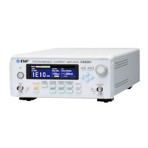
NF CA5350 User manual

NF Corporation
PROGRAMMABLE CURRENTAMPLIFIER
CA5350
Instruction Manual


PROGRAMMABLE CURRENTAMPLIFIER
CA5350
Instruction Manual
DA00043807-003


CA5350
i
―――Preface ―――
Thank you very much for purchasing our “CA5350 PROGRAMMABLE
CURRENT AMPLIFIER”.
To ensure safe and proper use of this electrical equipment, please read first
“Safety Precautions” on the following pages.
Caution Symbols Used in This Manual
The following caution symbols are used in this manual. Be sure to observe these caution
symbols and their contents to ensure the safety of the user and avoid damage to the
equipment.
Equipment handling could result in death or serious injury. This symbol contains
information to avoid such risk.
Equipment handling could result in minor or moderate injury or property damage.
This symbol contains information to avoid such risk.
The scope of this Manual
This manual describes the CA5350 that conform to requirements of CE Marking.
Products without CE Marking affixed, may not meet derectives for CE Marking (EMC and
others). Please confirm the CE Marking is affixed on the rear panel.
If using this equipment for the first time, start from “1. OUTLINE”.
1. OUTLINE
This chapter describes the overview, features, applications, functions and simple
operation principle of this product.
2. PREPARATIONS BEFORE USE
This chapter describes important preparation before installation and operation.
3. PANEL FEATURES AND BASIC OPERATIONS
This chapter describes the functions and simple operations available for each part in
the panel. Read while operating the equipment.
4. ADVANCED OPERATIONS
This chapter describes advanced operations.
5. REMOTE CONTROL
This chapter describes remote control through GPIG or USB.
6. TROUBLESHOOTING
This chapter describes how to deal with error messages and troubles.
7. MAINTENANCE
This chapter describes storage, repacking transportation as well as performance
testing.
8. SPECIFICATIONS
This chapter describes the product’s specifications (functions and performance).
CAUTION
WARNING

CA5350
ii
――― Safety Precautions ―――
To ensure safe use, be sure to observe the following warnings and cautions.
NF Corporation shall not be held liable for damages that arise from a failure to observe
these warnings and cautions.
This product is a Class I product (with protective conductor terminal) that conforms to the
JIS and IEC insulation standards.
Be sure to observe the contents of instruction manual.
This instruction manual contains information for the safe operation and use of this
product.
Be sure to read this information first before using this product.
All the warnings in the instruction manual must be heeded to prevent hazards that
may cause major accidents.
Be sure to ground the product.
To prevent electric shock, be sure to safety implement grounding such that ground
resistance is 100Ω or lower.
This product is automatically grounded when its three-pin power supply plug is
connected to the power outlet with a protective-ground contact.
When using a three-pin to two-pin conversion adapter, be sure to connect the grounding
wire of the adapter to the grounding terminal next to the outlet.
Check the power supply voltage
This product operates under the power supply voltage indicated in “Grounding and
Power Supply Connection” in this instruction manual.
Before connecting the power supply, check that the voltage of the power supply matches
the rated power supply of this product.
Observe the fuse rating
Using an unspecified fuse could cause a fire. Use the rated fuse specified in “Grounding
and Power Supply Connection” of the instruction manual.
Also, when replacing the fuse, the power cord must be disconnected from the power
outlet.
In case of suspected anomaly
If this product emits smoke, an abnormal smell, or abnormal noise, immediately power
it off and stop using it.
If such an abnormal occurs, prevent anyone from using this product until it has been
repaired, and immediately report the problem to NF Corporation or one of our
representatives.
Do not use this product when there is gas around.
An explosion or other such hazard may occur.

CA5350
iii
WARNING
Do not remove the cover.
This product contains high-voltage parts. Absolutely never remove its cover. Even when
the inside of this product needs to be inspected, do not touch the inside. All such
inspections should be performed by service technicians designated by NF Corporation.
Do not modify this product.
Absolutely never modify this product, as this may cause new hazards and may
disqualify this product from repair in case of failure.
Ensure that water does not get into this product or it does not get wet.
Using the product in wet condition may cause electric shock and fire. When water etc.
get into the product, immediately pull out the power supply cord, and contact NF
Corporation or one of our representatives from where you bought the product.
In the event of thunderstorm in the nearby area, turn off the power supply switch, and
pull out the power supply cord.
Thunderstorm may cause electric shock, fire, and breakdown.
Safety-related symbols
The general definitions of the safety-related symbols used on this product and in the
instruction manual are provided below.
Instruction Manual Reference Symbol
This symbol is displayed to alert the user to potential danger and
refer him/her to the instruction manual.
Electric Shock Danger Symbol
This symbol indicates locations that present a risk of electric
shock under specific conditions.
Warning Symbol
This symbol indicates information for the avoidance of a hazard such
as electric shock that may endanger human life or cause serious injury
during handling of the equipment.
Caution Symbol
This symbol indicates information for minor or moderate injury, or
property damage to the equipment during handling.
●Other Symbols
This symbol indicates the “on” position of the power switch.
This symbol indicates the “off” position of the power switch.
This symbol indicates that external conductor of the connector is
connected to the case.
This symbol indicates that the external conductor of connector is
connected to the signal ground.
CAUTION

CA5350
iv
──── Electromagnetic Compatibility ────
This product may cause interference if used in residential areas. Such use must be avoided
unless the user takes special measures to reduce electromagnetic emissions to prevent
interference to the reception of radio and television broadcasts.
──── Note on Waste Processing ────
To protect the environment, ensure that this device is disposed of by an appropriate
industrial waste processor. This product does not use batteries or a backlight that contains
mercury.

Contents
CA5350
v
Contents
Page
1. OUTLINE ......................................................................................................................1-1
1.1 Features ................................................................................................................1-2
1.2 Applications...........................................................................................................1-2
1.3 List of Functions ....................................................................................................1-3
1.4 Principle of Operation............................................................................................1-4
2. PREPARATIONS BEFORE USE..................................................................................2-1
2.1 Checking Before Use.............................................................................................2-2
2.2 Installation .............................................................................................................2-3
2.2.1 General Precautions for Installation................................................................2-3
2.2.2 Installation Conditions ....................................................................................2-3
2.2.3 Rack Mounting................................................................................................2-4
2.3 Grounding and Power Supply Connection ...........................................................2-13
2.4 Simplified Operation Check .................................................................................2-15
2.4.1 Checking operation and display at power on ................................................2-15
2.4.2 Checking key operation and response..........................................................2-15
2.5 Calibration ...........................................................................................................2-16
3. PANEL FEATURES AND BASIC OPERATIONS ..........................................................3-1
3.1 Panel Component Names and Functions...............................................................3-2
3.1.1 Front panel .....................................................................................................3-2
3.1.2 Rear panel......................................................................................................3-3
3.2 Display at Power “ON” and Initial Setting ...............................................................3-4
3.2.1 Displays and Indications at Power “ON” .........................................................3-4
3.2.2 Initialization.....................................................................................................3-5
3.3 I/O Terminals .........................................................................................................3-6
3.4 I/O Connection.......................................................................................................3-9
3.4.1 Connection of optical sensor (photodiode)....................................................3-10
3.4.2 Connection with lock-in amplifier, etc............................................................3-12
3.5 Operation Tree.....................................................................................................3-13
3.6 Basic Operation Examples...................................................................................3-15
3.6.1 Basic Key Operations ...................................................................................3-15
3.6.2 Simplified Operating Method When You Use Device for the First Time.........3-17
3.6.3 Initialization...................................................................................................3-18
3.6.4 Basic Settings...............................................................................................3-19
3.6.4.1 Input switching .........................................................................................3-19
3.6.4.2 Zero Check ..............................................................................................3-19

Contents
CA5350
vi
3.6.4.3 Gain Setting.............................................................................................3-19
3.6.4.4 Filter Setting.............................................................................................3-20
4. ADVANCED OPERATIONS ..........................................................................................4-1
4.1 Zero Check............................................................................................................4-2
4.2 Cancelling the dark current of sensor ....................................................................4-3
4.2.1 Manually setting the current value to be cancelled .........................................4-4
4.2.2 Automatically deciding the current value to be cancelled................................4-4
4.3 Setting DC Bias Voltage ........................................................................................4-6
4.4 Saving/Recalling the Settings................................................................................4-7
4.5 Self-diagnosis........................................................................................................4-8
4.6 Adjusting the LCD backlight brightness .................................................................4-9
4.7 Checking Various Information..............................................................................4-10
4.7.1 Checking the Version....................................................................................4-10
4.7.2 Checking the Production Number .................................................................4-10
4.7.3 Checking USB related ID..............................................................................4-10
5. REMOTE CONTROL....................................................................................................5-1
5.1 Preparations Before Use .......................................................................................5-2
5.1.1 Remote Control Interface Selection................................................................5-2
5.1.2 Outline of USB................................................................................................5-3
5.1.2.1 Preparation of Controller............................................................................5-3
5.1.2.2 Preparation of CA5350...............................................................................5-3
5.1.2.3 USB Device Identification...........................................................................5-3
5.1.3 Outline of GPIB...............................................................................................5-4
5.1.3.1 Preparation of Controller............................................................................5-4
5.1.3.2 Preparation of CA5350...............................................................................5-4
5.1.3.3 Precautions on Use of GPIB ......................................................................5-4
5.1.3.4 Basic Specifications of GPIB......................................................................5-5
5.1.4 Precautions on Communication ......................................................................5-5
5.2 Switching between Remote State and Local State.................................................5-6
5.3 Response to Interface Message ............................................................................5-7
5.4 Service Request and Status Byte ..........................................................................5-8
5.4.1 Service Request .............................................................................................5-8
5.4.2 Status Byte .....................................................................................................5-8
5.5 Commands Explanation.........................................................................................5-9
5.6 Description of Individual Command .....................................................................5-11
5.7 Multiline Interface Messages ...............................................................................5-22
6. TROUBLESHOOTING..................................................................................................6-1
6.1 Error Messages .....................................................................................................6-2
6.1.1 Errors at Power "ON"......................................................................................6-2

Contents
CA5350
vii
6.1.2 Errors at Panel Operation...............................................................................6-3
6.1.3 Error during Operation....................................................................................6-3
6.1.4 Errors in Remote Control................................................................................6-3
6.2 When the Device Appears to be a Problem ...........................................................6-4
7. MAINTENANCE............................................................................................................7-1
7.1 Introduction............................................................................................................7-2
7.2 Daily Maintenance.................................................................................................7-2
7.3 Storage, Repackaging, and Transport....................................................................7-3
7.4 Checking the Version Number ...............................................................................7-3
7.5 Performance Testing .............................................................................................7-4
7.5.1 Current suppression setting accuracy, gain accuracy .....................................7-5
7.5.2 Output offset voltage.......................................................................................7-6
7.5.3 DC bias voltage setting accuracy....................................................................7-6
7.6 Calibration .............................................................................................................7-7
8. SPECIFICATIONS........................................................................................................8-1
8.1 Specifications ........................................................................................................8-2
8.1.1 Input section...................................................................................................8-2
8.1.2 Current suppression section ...........................................................................8-3
8.1.3 Amplifier section .............................................................................................8-3
8.1.4 Output section ................................................................................................8-4
8.1.5 DC bias voltage output section .......................................................................8-4
8.1.6 General information........................................................................................8-5
8.2 External Dimensions..............................................................................................8-7

CA5350
viii
Figures
Page
Figure 1–1 Block Diagram ...............................................................................................1-4
Figure 2-1 Dimensional drawing of rack-mount (EIA, for 1 unit).......................................2-5
Figure 2-2 Dimensional drawing of rack-mount (EIA, for 2 units) .....................................2-6
Figure 2-3 Dimensional drawing of rack-mount (JIS, for 1 unit) .......................................2-7
Figure 2-4 Dimensional drawing of rack-mount (JIS, for 2 units)......................................2-8
Figure 2-5 Assembly drawing of rack-mount kit (EIA, for 1 unit) ......................................2-9
Figure 2-6 Assembly drawing of rack-mount kit (EIA, for 2 units)...................................2-10
Figure 2-7 Assembly drawing of rack-mount kit (JIS, for 1 unit).....................................2-11
Figure 2-8 Assembly drawing of rack-mount kit (JIS, for 2 units) ...................................2-12
Figure 3-1 Front panel .....................................................................................................3-2
Figure 3-2 Rear panel......................................................................................................3-3
Figure 3-3 I/O Terminals ..................................................................................................3-6
Figure 3-4 Input terminal..................................................................................................3-7
Figure 3-5 Output terminal...............................................................................................3-7
Figure 3-6 Output polarity................................................................................................3-7
Figure 3-7 DC bias voltage output terminal......................................................................3-8
Figure 3-8 Connection of sensor without bias ................................................................3-10
Figure 3-9 Connection of reverse bias sensor ...............................................................3-10
Figure 3-10 Example of connection with photomultiplier ................................................3-11
Figure 3-11 When the signal source is grounded...........................................................3-12
Figure 3-12 When the signal source cannot be grounded..............................................3-12
Figure 3-13 CA5350 outline block diagram ....................................................................3-20
Figure 3-14 Definition of the startup time .......................................................................3-22
Figure 4-1 Input circuit.....................................................................................................4-2
Figure 4-2 Block diagram of current suppression.............................................................4-3
Figure 4-3 Connecting to DC bias voltage .......................................................................4-6
Figure 8-1 CA5350 External Dimensions .........................................................................8-7

CA5350
ix
Tables
Page
Table 2–1 Package contents............................................................................................2-2
Table 3-1 Setting items and initial values list....................................................................3-5
Table 3-2 I/V Gain Settings and Auto-Filter Settings ......................................................3-21
Table 3-3 Filter setting and settling time.........................................................................3-23
Table 3-4 Filter setting and bandwidth ...........................................................................3-23
Table 4-1 Current suppression setting range and resolution ............................................4-3
Table 5-1 Responses to interface messages ...................................................................5-7
Table 5-2 Status Byte.......................................................................................................5-8
Table 5-3 Priority of Execution of Commands ..................................................................5-9
Table 5-4 Header List.....................................................................................................5-11
Table 6-1 Error message list at Power "ON" ....................................................................6-2
Table 6-2 List of error messages when operating the panel .............................................6-3
Table 6-3 List of error messages during operation ...........................................................6-3
Table 6-4 List of error messages during remote control ...................................................6-3
Table 6-5 When the device appears to be a problem .......................................................6-4

CA5350
1-1
1. OUTLINE
1.1 Features................................................................1-2
1.2 Applications...........................................................1-2
1.3 List of Functions....................................................1-3
1.4 Principle of Operation............................................1-4

1.1 Features
CA5350
1-2
1.1 Features
“CA5350 PROGRAMMABLE CURRENT AMPLIFIER” is the current input type
preamplifier that converts the input current signal from photo multiplier or photo diode
into voltage signal. It has both high gain and wide frequency band, and can be varied
over a wide range from 10k (V/A) to 10G(V/A). Besides, it is equipped with filters with
rise time from 1µs to 300ms, which allows removing unnecessary noise components and
improve SNR (signal noise ratio) of the signal. Furthermore, it is also equipped with a
current suppression unit(±8nA ~ ±800µA full scale) for cancelling dark current of the
sensor.
This product also has GPIB and USB interface, by which gain and various other
settings can be changed from the external controllers such as a personal computer.
Automatic measurement system can also be easily built.
High sensitivity, wide band
DC ~ 14kHz (response speed 25µs) when 10G(V/A) and DC ~ 500kHz (response speed
0.7µs) when 1M(V/A).
Stable with respect to the source capacitance
Even when the source capacitance of 1000pF is added, it operates stably without any
concerns of oscillations. Besides, overshoot and ringing will not occur in the pulse
response.
Variable Gain
Gain can be set in the range of 10k(V/A) ~ 10G(V/A) with a step by 10 times (7 range).
Moreover, by setting the output amplifier to ×10 times, maximum 100G(V/A) of gain
setting is possible.
Variable Filters
It is equipped with filters (low pass filter) with the rise time in the range of 1µs ~ 300ms
by 1-3 sequence in 12 ways. They can remove the noise components and improve the
SNR.
Current suppression
It is equipped with current suppression for cancelling the dark current of sensor. It
covers the full scale ±8nA ~ ±800µA in 6 range.
Remote control
Because USB and GPIB interfaces are equipped as standard features, you can build an
automatic measurement system.
1.2 Applications
High sensitivity detection of output current signal from photomultiplier or photo
diode.
Measuring weak electrical current signal from electrochemical cells
Material research of dielectric substances, etc.

1.3 List of Functions
CA5350
1-3
1.3 List of Functions
The following shows the outline of functional tree of CA5350.
Back light control Brightness adjustment
Gain I/V gain
Output amplifier gain
Filter On, Off
Rise time (manual, automatic)
Current suppression On, Off, Auto
Range
Current value
Voltage bias On, Off
Voltage value
Zero Check On, Off
Setting Save setting, recall setting
Remote control GPIB
USB
Self-check Self-check, version display, etc.

1.4 Principle of Operation
CA5350
1-4
1.4 Principle of Operation
The current signal input to CURRENT INPUT is amplified to a voltage signal by I/V
Amp, and output by an output amplifier after a low pass filter.
CURRENT
INPUT
CURRENT
SUPPRESSION
×1
×10
1μs~300ms
/OFF
INPUT
OVER
DETECT
10G/1G/100M
/10M/1M
/100k/10k
INVERTING
OUTPUT
OUTPUT
OVER
DETECT
SYSTEM
CONTROLLER
FRONT
PANEL USB GPIB
POWER
SUPPLY
100V/120V/
220V/240V
~ LINE
INVERTING
BIAS OUTPUT BIAS
ANALOG UNIT
INVERTING
BIAS OUTPUT
INVERTING
OUTPUT
CURRENT
INPUT
I/V
Amp
Output
Amp
FILTER
≒20Ω
ZERO
CHECK
Figure 1–1 Block Diagram
ZERO CHECK
It disconnects the input connection and cut off the input current. It is used to check
whether there is current output from the sensor, or output offset from CA5350 itself.
CURRENT SUPPRESSION
It is equipped with CURERNT SUPPRESSION for canceling the offset current of the
sensor. Since the canceling offset current can be set up to ±0.8mA, and it is possible to
set a huge gain of I/V Amp, it can be well detected in high sensitivity even a weak
change in the current.

1.4 Principle of Operation
CA5350
1-5
FILTER
It is equipped with filter that allows setting the rise time in the range of 1µs ~ 300ms in
by 1-3 sequence. You can remove unnecessary noise components and extract the
required signal component.
BIAS
For sensors those require DC bias, voltage bias source equipped that allows to output
any DC voltage in the range of -8V to +8V (resolution 0.001V) will be useful.
SYSTEM CONTROLLER
System controller sets and controls the analog parts according to user operations, and it
displays various information on the front panel LCD. Besides, it can also communicate
(remote I/F control) with the host controller.

CA5350
2-1
2. PREPARATIONS BEFORE USE
2.1 Checking Before Use ...................................................................2-2
2.2 Installation....................................................................................2-3
2.2.1 General Precautions for Installation.........................................2-3
2.2.2 Installation Conditions .............................................................2-3
2.2.3 Rack Mounting ........................................................................2-4
2.3 Grounding and Power Supply Connection..................................2-13
2.4 Simplified Operation Check........................................................2-15
2.4.1 Checking operation and display at power on .........................2-15
2.4.2 Checking key operation and response...................................2-15
2.5 Calibration..................................................................................2-16

2.1 Checking Before Use
CA5350
2-2
2.1 Checking Before Use
Safety check
Before using CA5350, make sure you have read “Safety Precautions”, Located at the
beginning of this instruction manual and observe the required cautions.
Before turning the power on, read “2.3 Grounding and Power Supply Connection” and
observe the necessary cautions.
Unpacking
Initially, check that the device has not been damaged during transit.
After unpacking, make sure that the contents listed in “Table 2-1 Package Contents”
are supplied.
Table 2–1 Package contents
CA5350 Main unit ................................................................................1
Accessories
Instruction Manual ...........................................................................1
Power Cord Set (3 Pole, 2m) .............................................................1
Fuse [Note1] (100V/120V: 1A or 220V/240V: 0.5A)..........................1
(Time lag,ø5.2 × 20mm)
[Note1] Fuse is built in the fuse holder.
This device contains high-voltage parts. Never remove the cover.
The internal parts of this device must only be serviced by an engineer
who has a thorough understanding of risk prevention.
WARNING
Table of contents
Other NF Amplifier manuals
