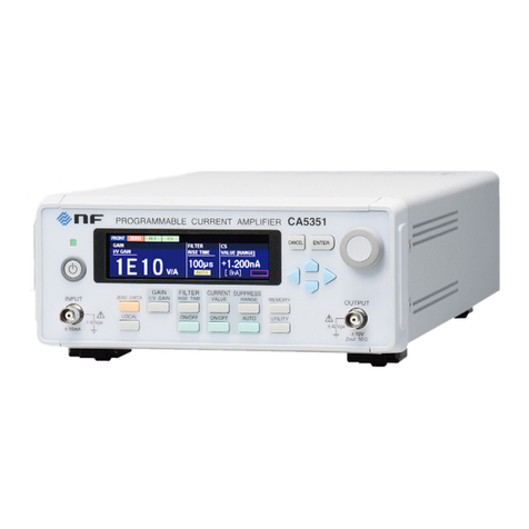
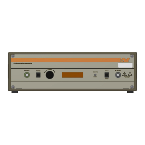
NF SA-200F3 User manual

NF Corporation
LOW NOISE AMPLIFIER
SA-200F3
INSTRUCTION MANUAL


DA00062385-001
LOW NOISE AMPLIFIER
SA-200F3
INSTRUCTION MANUAL


i SA-200F3
――― Preface ―――
Thank you for purchasing the SA-200F3 low noise amplifier.
Please read "Safety Information" on the next page first to ensure the product is used in a
correct and safe manner.
● Alert symbols in this manual
This manual uses the following alert symbols. The instructions next to these symbols must be
carefully obeyed to ensure the equipment operator’s safety and prevent damage to equipment.
This contains information for avoiding electric shock and other risks when handling the
equipment that could result in death or bodily injury to the operator.
This contains information for avoiding risks when handling the equipment that could result
in minor or moderate injury to the operator or damage to property.
● This manual consists of the following chapters.
1. Outline
This chapter gives an overview and describes the features and applications of this product and
the simple operating principle of the product.
2. Preparation before Use
This chapter describes important preparations to be made before installation and operation.
3. Panel Features and Basic Operations
This chapter explains the basic operations of the panels.
4. Maintenance
This chapter describes a method for simply inspecting operation.
5. Specifications
This chapter gives specifications (functions and performance).
6. Reference Data
This chapter shows the general electrical characteristics of a normal SA-200F3.
CAUTION
WARNING

ii SA-200F3
────Safety Information────
To ensure safe use, be sure to observe the following safety precautions.
NF Corporation shall not be held liable for damages that arise from a failure to observe these safety
precautions or warnings or cautions in the instruction manual.
Be sure to observe the information of the instruction manual.
The instruction manual contains information for the safe operation of the product.
Be sure to read the information first before using the product.
All the warnings in the instruction manual are intended for preventing risks that may lead to
serious accidents. Ensure to obey them.
Be sure to ground the product.
To prevent electric shock, the enclosure must be connected to an electrical ground.
Check the power supply voltage.
This product operates on the power supply voltage indicated in the instruction manual.
Prior to connecting the power supply, check that the voltage of the power supply matches the
rated power supply of the product.
If you notice anything strange
If this product emits smoke, an unusual smell, or abnormal noise, immediately power it off and
stop using it.
If such an anomaly occurs, prevent anyone from using this product until it has been repaired, and
immediately report the problem to NF Corporation or one of our representatives.
Do not operate in an explosive atmosphere.
An explosion or other such hazard may result.
Do not remove the cover.
The product may contain high-voltage parts. Never remove the cover.
Even when the inside of this product needs to be inspected, do not touch the inside. All such
inspections are to be performed by service technicians designated by NF Corporation.
Do not modify the product.
Never modify the product. Modification to the product may pose a new risk. We may refuse the
repair of a modified product.
Ensure that water does not get into this product.
Using the product in wet condition may cause electric shock and fire. When water etc. get into the
product, immediately power it off, and contact NF Corporation or one of our representatives.
If lightning occurs, power off and disconnect this product.
A lightning may cause an electric shock, a fire and a failure.

iii SA-200F3
Safety Information
WARNING
Electromagnetic compatibility
This product is a CISPR 11 Group 1 Class A compliant device. This product may cause
interference if used in residential areas. Such use must be avoided unless the user takes special
measures to reduce electromagnetic emissions to prevent interference to the reception of radio
and television broadcasts.
●Safety symbols
Caution, refer to instruction manual
This notifies the user of potential hazards and indicates that he/she must refer to the
instruction manual.
Caution, possibility of electric shock
This indicates that an electric shock may occur under specific conditions.
Protective earth ground terminal
This indicates that the terminal needs to be grounded in order to prevent electric shock
accidents.
Before operating the product, ensure to connect this terminal to an earth ground.
Warning
This contains information to avoid risks in equipment handling that could
result in loss of life or bodily injury.
Caution
This contains information to avoid risks in equipment handling that could
result in minor or moderate injury to person or damage to property or the
equipment.
●Other symbols
This indicates that the terminal or the outer conductor of the connector is connected to
the enclosure.
This indicates that the terminal or the outer conductor of the connector is connected to
the signal ground.
This indicates that the terminal or the outer conductor of the connector is isolated from
the enclosure.
It indicates, however, that the difference of the potential from the ground potential is
restricted to 42 Vpk or less for safety (this product is used grounded so the enclosure
potential and ground potential are equal).
Waste disposal
For environmental protection, do not discard this product in domestic household waste. This
product shall be disposed of through an appropriate industrial waste disposer.
CAUTION

iv SA-200F3
Contents
Page
Preface i
Safety Information ii
1. Outline....................................................................................................................1-1
1.1 Overview ................................................................................................................1-1
1.2 Features.................................................................................................................1-1
1.3 Operating Principle.................................................................................................1-2
2. Preparation before Use ..........................................................................................2-1
2.1 Check Appearance and Accessories......................................................................2-1
2.2 Conditions for Installation Location ........................................................................2-2
2.3 Power Supply .........................................................................................................2-2
2.4 Connecting with Low Noise DC Power Supply LP Series......................................2-3
2.5 Connecting to Power Supply other than LP Series ................................................2-4
3. Panel Features and Basic Operations ...................................................................3-1
3.1 Panel Component Names and Functions...............................................................3-1
3.2 Input Connection and Installation...........................................................................3-3
3.3 Output Connection .................................................................................................3-4
3.4 Warm-up Time........................................................................................................3-4
4. Maintenance...........................................................................................................4-1
4.1 Before Maintenance...............................................................................................4-1
4.2 Consumption Current with No Signal .....................................................................4-2
4.3 Operation Test........................................................................................................4-2
5. Specifications .........................................................................................................5-1
5.1 Non-Destructive Maximum Ratings........................................................................5-1
5.2 Electrical Characteristics........................................................................................5-1
5.2.1 Input ................................................................................................................5-1
5.2.2 Output..............................................................................................................5-2
5.2.3 Amplifier ..........................................................................................................5-2
5.2.4 Power supply...................................................................................................5-2
5.3 General...................................................................................................................5-3
5.4 External View .........................................................................................................5-4
5.5 External Dimensions of Bottom Plate.....................................................................5-5
6. Reference Data ......................................................................................................6-1
6.1 Reference Data ......................................................................................................6-1
6.2 Equivalent Input Noise Voltage Density .................................................................6-1
6.3 Voltage Gain Frequency Characteristic..................................................................6-2
WARRANTY

v SA-200F3
Figures and Tables
Page
Figure 1-1 Block diagram .................................................................................................1-2
Figure 2-1 Connecting to LP series power supply............................................................2-3
Figure 2-2 Connecting to power supply other than dedicated power supply....................2-4
Figure 3-1 Front and rear panel views..............................................................................3-2
Figure 4-1 Connection diagram for operation test............................................................4-2
Figure 4-2 Input voltage waveforms and output voltage waveforms ................................4-3
Figure 5-1 External view...................................................................................................5-4
Figure 5-2 External dimensions of bottom plate...............................................................5-5
Figure 6-1 Equivalent input noise voltage density from 1 Hz to 800 kHz.........................6-1
Figure 6-2 Voltage gain frequency characteristic from 1 kHz to 10 MHz .........................6-2
Table 2-1 List of contents..................................................................................................2-1


1. Outline
1.1 Overview................................................................................................................ 1-1
1.2 Features................................................................................................................. 1-1
1.3 Operating Principle .............................................................................................. 1-2

1.1 Overview
1-1 SA-200F3
1.1 Overview
The SA-200F3 is an ultra-low-noise amplifier realizing equivalent input noise voltage density of 0.5
nV/ Hz. Furthermore, it has 100 times gain and a wide bandwidth (DC to 800 kHz) with keeping a low
drift (0.2 µV/°C).
By adopting a low noise circuit with negative feedback technology, the SA-200F3 realizes both
excellent DC characteristic and ultra–low-noise characteristic.
1.2 Features
a) Ultra low noise
Equivalent input noise voltage density: 0.5 nV/ Hz
b) Wide bandwidth
Bandwidth: DC to 800 kHz
c) DC stability
DC drift: ±0.2 µV/°C
d) Selectable input impedance
Three selections: 1 kΩ, 10 kΩand 100 kΩ

1.3 Operating Principle
1-2 SA-200F3
1.3 Operating Principle
A1 is a non-inverting amplifier. Bipolar transistors are used for the first stage circuit. The input
impedance is selected by a rotary switch. A2 is the other non-inverting amplifier composed of an
OPamp. The gain of A1 is 50 times, and that of A2 is 2 times, so the total gain is 100 times (40 dB).
Figure 1-1 Block diagram


2. Preparation before Use
2.1 Check Appearance and Accessories...................................................................... 2-1
2.2 Conditions for Installation Location .................................................................... 2-2
2.3 Power Supply ........................................................................................................ 2-2
2.4 Connecting with Low Noise DC Power Supply LP Series .................................. 2-3
2.5 Connecting to Power Supply other than LP Series............................................. 2-4

2.1 Check Appearance and Accessories
2-1 SA-200F3
2.1 Check Appearance and Accessories
If you notice that something is out of order on the outside of the packing box (such as a deep
scratch or dent), closely check that the product is not affected when you remove it from the box.
When you take the contents out of the box, check them. If you find a deep scratch or dent on the
product or an accessory is missing, report the problem to the NF Corporation or one of our
representatives.
●Appearance check
Check that there are no deep scratches or dents on the panel surfaces, connectors, etc.
●Product configuration check
Table 2-1 shows the list of contents. Check that the quantities are correct and that there are no
deep scratches or dents.
Table 2-1 List of contents
●SA-200F3 ・・・・・・・・・・・・・・・・・・・・・・・・・・・・・・・・・・・・・・1
●Instruction manual ・・・・・・・・・・・・・・・・・・・・・・・・・・・・・1
●Accessory
Bottom plate ・・・・・・・・・・・・・・・・・・・・・・・・・・・・・1

2.2 Conditions for Installation Location
2-2 SA-200F3
2.2 Conditions for Installation Location
●The installation location shall meet the following temperature and humidity conditions.
Performance guarantee: +23±5 C, 10 to 90 %RH
Operating conditions: 0 to +40 C, 10 to 90 %RH
Storage conditions: −10 to +50 C, 10 to 80 %RH
However, do not use the product if condensation is present.
●Use the product indoors at an altitude of up to 2000 m.
● Do not install the product in the following locations.
・Locations where flammable gases may be present
There is risk of explosion. Never install or use the product in such locations.
・Outdoors, locations exposed to direct sunlight, or near fire or heat sources
The expected performance of this product may not be exhibited, or a malfunction may
result.
・Location where corrosive gases, water vapor, or dust may be present or humid location
This product may become corroded, or a malfunction may result.
・Near an electromagnetic field source, high-voltage product, or power line
Noise may increase.
・Location where there is a lot of vibration
Noise may increase or a malfunction may result.
2.3 Power Supply
This product operates under the following power supply conditions.
To obtain the best noise characteristics, we recommend Low Noise DC Power Supply LP series.
・Stabilized DC power supply with ±15 V ±5 %, +15 V: +50 mA or higher, −15 V: −50 mA or higher
(a switching power supply is not recommended).
This product will be damaged by reversely connecting the power supply. Supplying a voltage
greater than ± 16.5 V will damage the internal circuits of this product.
Attention

2.4 Connecting with Low Noise DC Power Supply LP Series
2-3 SA-200F3
2.4 Connecting with Low Noise DC Power Supply LP Series
To connect this product to a dedicated LP series power supply, use the output cable B
(PA-001-2373). Check that the output switch of the LP series is set to OFF. Connect the black line
to the GND lug of this product, the pink line to the +15 V terminal, and the white line to the −15 V
terminal.
Figure 2-1 Connecting to LP series power supply
・If the power supply is reversely connected, the internal circuits will be damaged.
・Do not apply excessive force to the cable while the cable is connected to this product. The
power supply pin of this product is easy to bend, and if strong force is applied, the pin may
break (if it should be damaged, a repair fee will be charged).
Attention
White
Pink
Black
Output cable B
(PA-001-2373)

2.5 Connecting to Power Supply other than LP Series
2-4 SA-200F3
2.5 Connecting to Power Supply other than LP Series
To connect this product to a DC power supply other than the dedicated LP series power supply,
connect the cable (by soldering it) as shown in the figure below.
Figure 2-2 Connecting to power supply other than dedicated power supply
・Be sure to carefully reconfirm the polarity and voltage of the power supply.
・If the power supply is reversely connected or a voltage of higher than ±16.5 V is applied, the
internal circuits will be damaged.
・Use a DC power supply that restricts the current to 150 mA.
Attention
−15 V DC
+15 V DC
GND (0 V)
Soldering
DC power supply
Power: OFF
±15 V±5 %, ±0.1 A
Ripple of 1 mVrms or less
Twisted cable:
length of 2 m or less

Table of contents
Other NF Amplifier manuals


