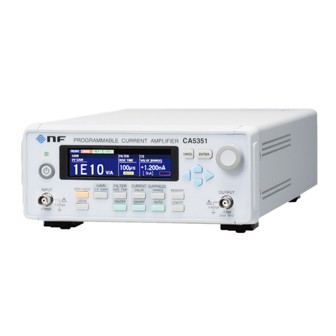
NF CA5360 User manual

NF Corporation
LOW NOISE PREAMPLIFIER
CA5360
INSTRUCTION MANUAL


DA00058741-001
LOW NOISE PREAMPLIFIE
R
CA5360
INSTRUCTION MANUAL


Preface
i CA5360
Preface
Thank you very much for purchasing our “CA5360 LOW NOISE PREAMPLIFIER”.
Please read, first of all, "Safety Precautions" on the follawing pages, to use the instrument in the
correct and safe manner.
Safety Symbols Used in This Manual
Be sure to observe these safety symbols and their contents to ensure the safety of user and avoid damage
to the equipment.
!WARNING
Equipment handling could result in death or serious injury. This symbol contains
information to avoid such risk.
!CAUTION
Equipment handling could result in minor or moderate injury or property damage. This
symbol contains information to avoid such risk.
This manual has the following chapters.
If using this equipment for the first time, start from Chapter 1.
1. OUTLINE
This chapter describes the overview, specificities, applications, functions and simple principle of
operations of this equipment.
2. PREPARATIONS BEFORE USE
This chapter describes important preparation before installation and operation.
3. OPERATION
This chapter describes the functions and basic operations
Read while operating the instrument.
4. MAINTENANCE
This chapter describes storage, repacking transportation as well as performance testing.
5. SPECIFICATION
This chapter describes the product’s specifications (functions and performance).

Safety Precautions
ii CA5360
Safety Precautions
To ensure safe use, be sure to observe the following safety precautions.
NF Corporation shall not be held liable for damages that arise from a failure to observe these safety
precautions or warnings or cautions in the instruction manual.
Be sure to observe the information of the instruction manual.
The instruction manual contains information for the safe operation of the product.
Be sure to read the information first before using the product.
All the warnings in the instruction manual are intended for preventing risks that may lead to serious
accidents. Ensure to obey them.
Check the power supply voltage.
This product operates on the power supply voltage indicated in the instruction manual.
Prior to connecting the power supply, check that the voltage of the power supply matches the rated
power supply of the product.
If you notice anything strange
If this product emits smoke, an unusual smell, or abnormal noise, immediately power it off and stop
using it.
If such an anomaly occurs, prevent anyone from using this product until it has been repaired, and
immediately report the problem to NF Corporation or one of our representatives.
Do not operate in an explosive atmosphere.
An explosion or other such hazard may result.
Do not remove the cover.
Even when the inside of this product needs to be inspected, do not touch the inside. All such
inspections are to be performed by service technicians designated by NF Corporation.
Do not modify the product.
Never modify the product. Modification to the product may pose a new risk. We may refuse the
repair of a modified product.
Ensure that water does not get into this product.
Using the product in wet condition may cause electric shock and fire. When water etc. get into the
product, immediately power it off, and contact NF Corporation or one of our representatives.
Electromagnetic compatibility
This product is a CISPR 11 Group 1 Class A compliant device. This product may cause interference
if used in residential areas. Such use must be avoided unless the user takes special measures to reduce
electromagnetic emissions to prevent interference to the reception of radio and television broadcasts.

Safety Precautions
iii CA5360
Safety symbols
Caution, refer to instruction manual
This notifies the user of potential hazards and indicates that he/she must refer to the
instruction manual.
Waste disposal
For environmental protection, do not discard this product in domestic household waste. This product
shall be disposed of through an appropriate industrial waste disposer.

Safety Precautions
iv CA5360
Table of Contents
Page
1. Outline ..............................................................................................................................1-1
1.1 Features....................................................................................................................1-2
1.2 Operating Principle..................................................................................................1-3
1.2.1 Basic Principle...................................................................................................1-3
1.2.2 Block Diagram...................................................................................................1-3
2. Preparation Before Use ....................................................................................................2-1
2.1 Checking Before Use ................................................................................................2-2
2.2 Installation Condition..............................................................................................2-3
2.3 Connecting to Power Supply....................................................................................2-3
3. Operation ..........................................................................................................................3-1
3.1 Part Names and Functions ......................................................................................3-2
3.2 Installation and Connection ....................................................................................3-5
3.3 Output.......................................................................................................................3-7
3.4 Warm up time...........................................................................................................3-7
4. Maintenance .....................................................................................................................4-1
4.1 Preface ......................................................................................................................4-2
4.2 Daily Maintenance ...................................................................................................4-2
4.3 Storage, Repacking, and Transportation ................................................................4-2
4.4 Performance Test......................................................................................................4-3
4.4.1 Gain Accuracy....................................................................................................4-4
4.4.2 Offset Voltage Check.........................................................................................4-5
5. Specifications....................................................................................................................5-1
5.1 Specifications............................................................................................................5-2
5.2 General Specifications .............................................................................................5-3
5.3 External Dimensions................................................................................................5-4

Safety Precautions
v CA5360
Figure 1-1 Block Diagram................................................................................................1-3
Figure 3-1 Top View..........................................................................................................3-2
Figure 3-2 Input Circuit (A−B, A (GND)) ........................................................................3-3
Figure 3-3 Input Circuit (A (FLOAT)) .............................................................................3-3
Figure 3-4 Output Circuit ................................................................................................3-4
Figure 5-1 Product Dimensions .......................................................................................5-4

1-1 CA5360
1. Outline
Page
1. Outline ..............................................................................................................................1-1
1.1 Features....................................................................................................................1-2
1.2 Operating Principle..................................................................................................1-3
1.2.1 Basic Principle...................................................................................................1-3
1.2.2 Block Diagram...................................................................................................1-3

1.1 Features
1-2 CA5360
1.1 Features
The “CA5360 LOW NOISE PREAMPLIFIER” is a low noise preamplifier for a lock-in
amplifier and a frequency response analyzer.
Low Noise
Input referred noise voltage is low with 5 nV/ Hz below.
It's most suitable for measurement of the very small voltage.
High Common Mode Rejection Ratio
The Common Mode Rejection Ratio is beyond 100 dB (below 100 Hz). It's most suitable
for very small voltage measurement with common mode voltage superimposed.
Wideband
A voltage signal of up to 1 MHz can be amplified by 100 times (40 dB).
High Input Impedance
The input impedance is 100 MΩ. It’s suitable for signal amplification from a high
output impedance sensor. Input mode can choose balance or unbalance and input
coupling can choose DC or AC.
Small Design
The size is 100(W) × 48(H) × 80(D) mm. You can put it in the side of a measurement
signal source.
DC Cable
DC cable PA-001-2372 attaches to this equipment.
When using locking-in amplifier LI5630,LI5640 or power supply PS-70A, please
purchase an option DC cable and use.
NOTE:
Accessory DC cable (PA-001-2372)
It corresponds to the following equipment.
LI5645 / LI5650 / LI5655 / LI5660 / LP5391 / LP5392 / LP5393 / LP5394
Option DC cable (PA-001-2791)
It corresponds to the following equipment.
LI5630 / LI5640 / PS-70A

1.2 Operating Principle
1-3 CA5360
1.2 Operating Principle
1.2.1 Basic Principle
A signal is input from front input connectors, and is changed by a pair of source followers
with low noise FETs to low impedance. The signal is supplied to a low noise differential
amplifier, amplified by 100 times, and output from the output connector in the rear.
1.2.2 Block Diagram
The following shows a schematic block diagram of the CA5360 and describes the main
function.
Figure 1-1 Block Diagram
a) Input Section
The input section has following functions.
Input connector selection (balance/unbalance)
Input coupling selection (DC/AC)
b) Offset Voltage Adjust
It's possible to adjust the offset voltage by potentiometer in a side.
c) Power Indicator
The LED which shows that equipment is in the turning on state can be disabled.

2-1 CA5360
2. Preparation Before Use
Page
2. Preparation Before Use ....................................................................................................2-1
2.1 Checking Before Use ................................................................................................2-2
2.2 Installation Condition..............................................................................................2-3
2.3 Connecting to Power Supply....................................................................................2-3

2.1 Checking Before Use
2-2 CA5360
2.1 Checking Before Use
Appearance Check
Check that the equipment has not been damaged during transport.
Unpacking
After unpacking, refer to "Table 2-1 Composition List" to check the contents.
Table 2-1 Composition List
Option
PA-001-2791 (DC cable, 2 m)
When using lock-in amplifier LI5630, LI5640 or power supply PS-70A, DC cable of an
accessory can't be used. After checking the products, please purchase an option DC cable
and use.
Note
PA-001-2372 for LI5645 / LI5650 / LI5655 / LI5660 / LP5391 / LP5392 / LP5393 / LP5394
PA-001-2791 for LI5630 / LI5640 / PS-70A
CA5360 ········································································· 1
Accessories
Instruction Manual ··················································· 1
DC cable (PA-001-2372, 2 m) ······································ 1
Coaxial cable (BNC-BNC, 1 m) ··································· 3

2.2 Installation Condition
2-3 CA5360
2.2 Installation Condition
●Install this equipment in a place that satisfies the following temperature and
humidity conditions.
Operation: 0 °C to +40 °C
, 5 %RH to 85 %RH (Absolute humidity 1 g/m3to 25 g/m3,
non-condensing)
Storage: −10 °C to +50 °C
, 5 %RH to 95 %RH (Absolute humidity 1 g/m3to 29 g/m3,
non-condensing)
●Install the device at an altitude below 2000 m.
!CAUTION
Avoid installation in the following locations.
Where there is flammable gas
There is a risk of explosion. Never install or use it in such a location.
Outdoors, where exposed to direct sunlight, or near fire or a heat source
The performance declines or a failure may occur.
Where there are corrosive gases and vapors, a lot of dust and particles, salty air
and oily smoke, and metal powder, etc.
Corrosion or a failure may occur.
Where there is a lot of vibration
Malfunction or a failure may occur.
Near an electromagnetic field source, high-voltage equipment, power line, or
pulse noise source
Malfunction or a failure may occur.
To ensure correct measurement, warm up the equipment for at least 30 minutes before use.
2.3 Connecting to Power Supply
The following shows the power supply conditions for this equipment.
Voltage range DC ±15 V, ±20 V or ±24 V ±5 %
Maximum ouput current less than 50 mA
Connecor HR10-7R-4P
!CAUTION
Don't supply this equipment with the voltage beyond ±25.2 V. Failure may occur.
When using the LP series power supply, set it to ±15 V output voltages before use.

3-1 CA5360
3. Operation
Page
3. Operation ..........................................................................................................................3-1
3.1 Part Names and Functions ......................................................................................3-2
3.2 Installation and Connection ....................................................................................3-5
3.3 Output.......................................................................................................................3-7
3.4 Warm up time...........................................................................................................3-7

3.1 Part Names and Functions
3-2 CA5360
3.1 Part Names and Functions
Figure 3-1 Top View
①
②
③
④
⑤
⑥
⑧⑦
⑨

3.1 Part Names and Functions
3-3 CA5360
○
1 INPUT CONNECTOR
This equipment has 2 signal input BNC (A, B). The input impedance is 100 MΩ. At DC
coupling, the maximum input voltage is ±12 V, at AC coupling, it’s DC ±40 V or AC ±12 Vpk.
When INPUT mode is A (FLOAT), the maximum input voltage between BNC outer contact
and the case is ±20 V. Any input voltage over the maximum may damage input stage of
this equipment and make it degrade.
Figure 3-2 Input Circuit (A−B, A (GND))
Figure 3-3 Input Circuit (A (FLOAT))
○
2 COUPLING SELECTOR
The switch to choose input coupling (DC, AC). Applying excessive force may break this
equipment.
!CAUTION
Change input select while no signal. Otherwase failure may occur.
○
3 INPUT SELECTOR
0.015 μF
100 MΩ
−12 V
+12 V
10 Ω
Input A
Input B
Input A 0.015 μF
0.015 μF
10 Ω
10 Ω
+12 V
−12 V
−12 V
+12 V
100 MΩ
100 MΩ±20 V

3.1 Part Names and Functions
3-4 CA5360
The switch to choose input channel (A, A−B). Applying excessive force may break this
equipment.
!CAUTION
Change input coupling while no signal. Otherwase failure may occur.
○
4 GND SELECTOR
The switch to choose the connection of input A’s outer contact (FLOAT, GND) when input
channel A is chosen. Applying excessive force may break this equipment.
○
5 OFFSET ADJUST
Inserting a suitable screwdriver enables to adjust the output offset voltage. Applying
excessive force may break this equipment.
○
6 LAMP
The switch to inactivate the power indicator. This switch is required by optical laboratories.
Applying excessive force may break this equipment.
○
7 OUTPUT CONNECTOR
The output connector is a BNC. Output impedance is 50 Ω. The maximum output current
is ±2.5 mA (2 kΩload at 5 V).
Note that this equipment can't drive 50 Ωload sufficiently.
Figure 3-4 Output Circuit
○
8 POWER INPUT
A power supply input connector of this equipment. DC cable of an accessory or option is
connected to this connector.
○
9 GROUND TERMINAL
This terminal is connected to the case. The case is connected to the common of the power
supply. If you want to connect the case to the ground, this terminal may be used.
+12 V
−12 V
50 Ω

3.2 Installation and Connection
3-5 CA5360
3.2 Installation and Connection
There are 3 way of connections between signal source and this equipment.
1) Balanced connection (A−B)
A signal source should be connected between input A and B. This equipment operates
in true differential mode. The ability to reject common mode noise is highest. This
connection can be used for every use.
2) Unbalanced connection
A (FLOAT)
A signal source should be connected to input A. The interior is differential input,
and the common of input A is floated. But the ability to reject common mode noise
is less than input mode A−B.
INPUT
A
B
+
-
×100
OUTPUT
INPUT
A +
-
×100
OUTPUT
Table of contents
Other NF Amplifier manuals
Popular Amplifier manuals by other brands
Opus Technologies
Opus Technologies eLoop Installation and user manual
AUSTRALIAN MONITOR
AUSTRALIAN MONITOR AMIS120P specification

Darkglass Electronics
Darkglass Electronics Microtubes 900 V2 owner's manual
McIntosh
McIntosh C-8S instruction manual
Ashly
Ashly INSTRUMENT PREAMP SC-40 operating instructions
IHOS
IHOS D Series owner's manual

Sonic Farm
Sonic Farm Xcalibur user manual
Clarion
Clarion XC6120 Owner's manual & installation manual

Demeter Amplification
Demeter Amplification HBP-1 H series user guide
thomann
thomann Harley Benton HB-15GXD JamBox user manual
GAS Car Audio
GAS Car Audio COMPETITION 7000.1D owner's manual
Ahuja
Ahuja SSA-250 M Operation manual
