NF CA5351 User manual

NF Corporation
PROGRAMMABLE CURRENT AMPLIFIER
CA5351
INSTRUCTION MANUAL


PROGRAMMABLE CURRENT AMPLIFIER
CA5351
INSTRUCTION MANUAL
DA00082422-001


i
――― Preface ―――
Thank you for purchasing the “CA5351 PROGRAMMABLE CURRENT AMPLIFIER”.
For safe and correct use of this product, please read the “Safety Precautions” section
that follows before attempting to use the instrument.
Marks and Symbols
For safe operation by the user and to prevent damage to the instrument, please give
attention to the following marks and symbols that are used in this manual.
! WARNING
This mark indicates information for preventing the possibility of death or serious
personal injury from electrical shock or other hazards in the use or handling of this
instrument.
! CAUTION
This mark indicates information for preventing the possibility of injury to the user
or damage to the instrument in the use or handling of this instrument.

ii
The chapters of this manual are described below
If you are using this instrument for the first time, begin reading from Chapter1.
1. Introduction
This chapter describes a general description of the instrument, including its
features, applications, functions, and basic operating principles.
2. Preparation before use
This chapter describes important preparation that must be done before operating
the instrument.
3. Panel operations and basic operation
This chapter describes the functions of the keys and knob on the panel, the
operating procedures of the screen, and the basic operating procedures of the
instrument.
Refer to this chapter as you use the instrument.
4. Advanced operation
This chapter describes a wide range of operations.
5. Remote control
This chapter describes remote control via USB, LAN, and GPIB interfaces.
6. Troubleshooting
This chapter describes how to deal with error messages and cases in which you
think the instrument is malfunctioning.
7. Maintenance
This chapter describes storage, repacking, transportation, and performance testing
methods.
8. Specifications
This chapter describes the instruments specifications (functions and performance).

iii
――― Safety Precautions ―――
For safe use of this product, give full attention to the following warnings and cautions.
The NF Corporation shall not be held liable for damages that arise from failure to
observe these warnings and cautions.
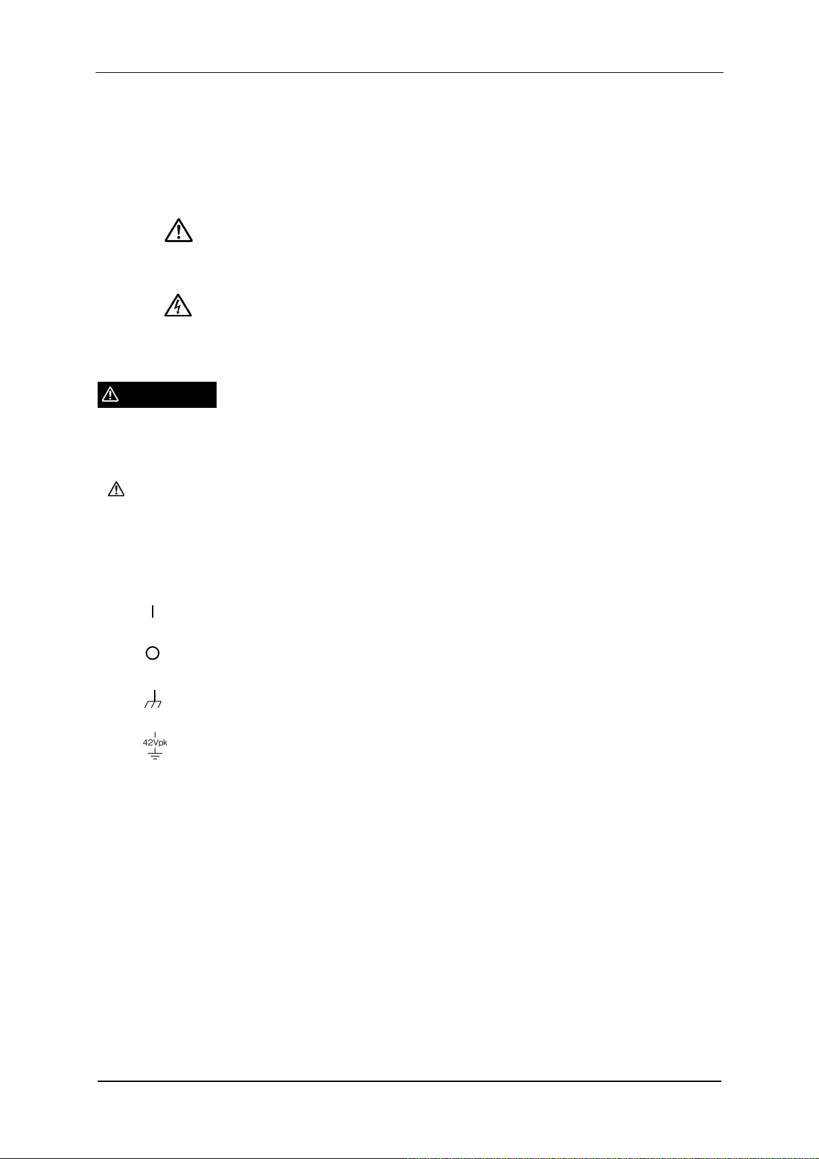
This product is a Class I product (with protective conductor terminal) that conforms to
the JIS and IEC insulation standards.
Be sure to observe the contents of instruction manual.
This instruction manual contains information for the safe operation and use of this
product.
Be sure to read this instruction before using this product.
All of the warning items contained in this instruction are intended to avoid risks that
may lead to serious accidents. Follow the warnings and instructions carefully.
Be certain that the product is properly grounded.
This product uses a line filter which may cause electric shock if the product is not
grounded.
To prevent electric shock accidents, connect the product to an earth ground so that
the ground resistance is 100 Ωor less.
This product is automatically grounded by connecting a 3-pin power plug to a power
outlet with a protective ground contact.
This product does not come with an accessory 3-pin to 2-pin power adapter. If you
must use your own adapter, be sure to connect the ground line of the adapter to
suitable ground near the power outlet.
If there is a ground terminal on the rear panel, you may connect the terminal to the
ground via a cable thicker than the power supply plug.
Check the power supply voltage.
This instrument operates on the power source voltage described in “Grounding and
power connections”.
Before plugging in the power cord, confirm that the outlet voltage conforms to the
rated power supply of this product.
Observe the fuse rating.
Using an unspecified fuse could cause a fire. Use the rated fuse specified in
“Grounding and power connections”.
Also, when replacing the fuse, unplug the power cord from a power outlet.

Safety Precautions
iv
If you think something is wrong, …
If smoke or an unusual odor or sound comes from the instrument, immediately
remove the power cord from the socket and cease use of the instrument.
If any such abnormality occurs, take measures to prevent the use of the instrument
until repairs have been completed and promptly contact the NF Corporation or its
authorized agent.
Do not use this product in explosive atmosphere.
An explosion or other hazards may occur.
Do not open the product case.
To prevent exposure of high voltages, never remove the cover of the instrument.
Only technicians certified by the NF Corporation are authorized to inspect and touch
anything inside the product case.
Do not modify this product.
Never modify this product in any way. Modification might create new risks. The NF
Corporation may refuse to service an instrument that has an unauthorized
modification.
Do not expose this product to water.
Use of this product when it is wet may result in electrical shock or fire. If the
instrument becomes wet, immediately unplug the power cord and contact the NF
Corporation or its authorized agent.
If lightning occurs nearby, turn off the power switch and unplug the power cord.
A lightning strike may cause electrical shock, fire, or instrument malfunction.
Electromagnetic compatiblity
This product is a CISPR 11 Group 1 Class A compliant instrument. This product may
cause interference if used in residential areas. Such use must be avoided unless the
user takes special measures to reduce electromagnetic emissions to prevent
interferene to the reception of radio and television broadcasts.

Safety Precautions
v
WARNING
Safety-related symbols
The marks and symbols defined below are used in this manual or on the instrument
itself to indicate safety information or instructions.
Instruction Manual Reference Symbol
This symbol notifies the user of a potential hazard and
indicates that the user must refer to the instruction manual.
Electric Shock Danger Symbol
This symbol indicates a location that presents a risk of
electric shock under specific conditions.
Warning Symbol
This mark indicates information for preventing the possibility
of death or serious personal injury from electrical shock or
other hazards in the use or handling of this instrument.
Caution Symbol
This mark indicates information for preventing the possibility
of injury to the user or damage to the instrument in the use or
handling of this instrument.
Other Symbols
Indicates that the “on” position of the power switch.
Indicates that the “off” position of the power switch.
Indicates that connected to the product case.
Indicates that the outer conductor of the connector is isolated from the
instrument enclosure. However, safe operation of the instrument requires
that the potential difference from the grounding potential is restricted to
42Vpk or less. This product is grounded when in use, so the electrical
potential of the instrument enclosure is equal to the ground potential.
CAUTION

Safety Precautions
vi
Disposal of this product
To protect the environment, follow the guidelines described below for the disposal of
this product.
a) Use the services of an industrial waste disposal contractor for disposal of the entire
product.
b) This product does not use batteries.
c) This product does not contain mercury.

Contents
vii
Contents
Page
1. Introduction ................................................................................................... 1-1
1.1 Features .................................................................................................................. 1-2
1.2 Applications ............................................................................................................. 1-3
1.3 List of Functions ...................................................................................................... 1-3
1.4 Operating principles ................................................................................................. 1-4
2. Preparation before use .................................................................................. 2-1
2.1 Inspection ................................................................................................................ 2-2
2.2 Installation ............................................................................................................... 2-3
2.3 Grounding and power connections ........................................................................ 2-10
2.4 Quick operation check ........................................................................................... 2-13
2.5 Calibration ............................................................................................................. 2-14
3. Panel operations and basic operation .......................................................... 3-1
3.1 Function and use of each part of the panels ............................................................ 3-2
3.2 Display at power “ON” and initial settings ................................................................ 3-4
3.3 I/O connectors ......................................................................................................... 3-8
3.4 I/O connections ...................................................................................................... 3-10
3.5 Operation tree ........................................................................................................ 3-14
3.6 Basic operation ...................................................................................................... 3-16
3.7 Basic settings ........................................................................................................ 3-22
4. Advanced operation ...................................................................................... 4-1
4.1 Utilities ..................................................................................................................... 4-2
4.2 Memory operation .................................................................................................... 4-7
5. Remote control .............................................................................................. 5-1
5.1 Preparations before use .......................................................................................... 5-2
5.2 Switching between remote and local modes ............................................................ 5-9
5.3 Responding to interface messages ........................................................................ 5-10
5.4 List of commands and command tree .................................................................... 5-11
5.5 Commands ............................................................................................................ 5-13
5.6 Status system ........................................................................................................ 5-33
5.7 Error messages ..................................................................................................... 5-40
5.8 Compatibility with commands of the CA5350 ......................................................... 5-42
5.9 Command execution examples .............................................................................. 5-51
6. Troubleshooting ............................................................................................. 6-1
6.1 Error messages ....................................................................................................... 6-2
6.2 Quick diagnosis ....................................................................................................... 6-7
7. Maintenance .................................................................................................. 7-1
7.1 Introduction .............................................................................................................. 7-2

Contents
viii
7.2 Daily Maintenance ................................................................................................... 7-2
7.3 Storage, repackaging, and transport ........................................................................ 7-3
7.4 Checking the version number .................................................................................. 7-3
7.5 Self-diagnostic test .................................................................................................. 7-3
7.6 Performance test ..................................................................................................... 7-4
7.7 Calibration ............................................................................................................... 7-7
8. Specifications ................................................................................................ 8-1
8.1 Input section ............................................................................................................ 8-2
8.2 Current suppression section .................................................................................... 8-3
8.3 Amplifier section ...................................................................................................... 8-4
8.4 Output section ......................................................................................................... 8-5
8.5 Miscellaneous specifications .................................................................................... 8-6
8.6 External dimensions ................................................................................................ 8-8

Figures and Tables
ix
Fi
g
ures and Tables
Page
Figure 1-1 Block diagram of the CA5351 ꞏꞏꞏꞏꞏꞏꞏꞏꞏꞏꞏꞏꞏꞏꞏꞏꞏꞏꞏꞏꞏꞏꞏꞏꞏꞏꞏꞏꞏꞏꞏꞏꞏꞏꞏꞏꞏꞏꞏꞏꞏꞏꞏꞏꞏꞏꞏꞏꞏꞏꞏꞏꞏꞏꞏꞏꞏꞏꞏꞏꞏꞏꞏꞏꞏꞏꞏ 1-5
Figure 2-1 Rack mounting kit assembly diagram (EIA for one unit) ꞏꞏꞏꞏꞏꞏꞏꞏꞏꞏꞏꞏꞏꞏꞏꞏꞏꞏꞏꞏꞏꞏꞏꞏꞏꞏꞏꞏꞏꞏꞏꞏꞏꞏ 2-6
Figure 2-2 Rack mounting kit assembly diagram (EIA for two units) ꞏꞏꞏꞏꞏꞏꞏꞏꞏꞏꞏꞏꞏꞏꞏꞏꞏꞏꞏꞏꞏꞏꞏꞏꞏꞏꞏꞏꞏꞏꞏꞏꞏ 2-6
Figure 2-3 Rack mounting kit assembly diagram (JIS for one unit) ꞏꞏꞏꞏꞏꞏꞏꞏꞏꞏꞏꞏꞏꞏꞏꞏꞏꞏꞏꞏꞏꞏꞏꞏꞏꞏꞏꞏꞏꞏꞏꞏꞏꞏ 2-7
Figure 2-4 Rack mounting kit assembly diagram (JIS for two units) ꞏꞏꞏꞏꞏꞏꞏꞏꞏꞏꞏꞏꞏꞏꞏꞏꞏꞏꞏꞏꞏꞏꞏꞏꞏꞏꞏꞏꞏꞏꞏꞏꞏ 2-7
Figure 2-5 Rack mounting kit dimensions (EIA for one unit) ꞏꞏꞏꞏꞏꞏꞏꞏꞏꞏꞏꞏꞏꞏꞏꞏꞏꞏꞏꞏꞏꞏꞏꞏꞏꞏꞏꞏꞏꞏꞏꞏꞏꞏꞏꞏꞏꞏꞏꞏꞏꞏꞏ 2-8
Figure 2-6 Rack mounting kit dimensions (EIA for two units) ꞏꞏꞏꞏꞏꞏꞏꞏꞏꞏꞏꞏꞏꞏꞏꞏꞏꞏꞏꞏꞏꞏꞏꞏꞏꞏꞏꞏꞏꞏꞏꞏꞏꞏꞏꞏꞏꞏꞏꞏꞏꞏ 2-8
Figure 2-7 Rack mounting kit dimensions (JIS for one unit) ꞏꞏꞏꞏꞏꞏꞏꞏꞏꞏꞏꞏꞏꞏꞏꞏꞏꞏꞏꞏꞏꞏꞏꞏꞏꞏꞏꞏꞏꞏꞏꞏꞏꞏꞏꞏꞏꞏꞏꞏꞏꞏꞏ 2-9
Figure 2-8 Rack mounting kit dimensions (JIS for two units) ꞏꞏꞏꞏꞏꞏꞏꞏꞏꞏꞏꞏꞏꞏꞏꞏꞏꞏꞏꞏꞏꞏꞏꞏꞏꞏꞏꞏꞏꞏꞏꞏꞏꞏꞏꞏꞏꞏꞏꞏꞏꞏ 2-9
Figure 2-9 Voltage selector switch ꞏꞏꞏꞏꞏꞏꞏꞏꞏꞏꞏꞏꞏꞏꞏꞏꞏꞏꞏꞏꞏꞏꞏꞏꞏꞏꞏꞏꞏꞏꞏꞏꞏꞏꞏꞏꞏꞏꞏꞏꞏꞏꞏꞏꞏꞏꞏꞏꞏꞏꞏꞏꞏꞏꞏꞏꞏꞏꞏꞏꞏꞏꞏꞏꞏꞏꞏꞏꞏꞏꞏꞏꞏꞏ 2-10
Figure 2-10 Fuse replacement ꞏꞏꞏꞏꞏꞏꞏꞏꞏꞏꞏꞏꞏꞏꞏꞏꞏꞏꞏꞏꞏꞏꞏꞏꞏꞏꞏꞏꞏꞏꞏꞏꞏꞏꞏꞏꞏꞏꞏꞏꞏꞏꞏꞏꞏꞏꞏꞏꞏꞏꞏꞏꞏꞏꞏꞏꞏꞏꞏꞏꞏꞏꞏꞏꞏꞏꞏꞏꞏꞏꞏꞏꞏꞏꞏꞏꞏꞏꞏ 2-12
Figure 3-1 Front panel ꞏꞏꞏꞏꞏꞏꞏꞏꞏꞏꞏꞏꞏꞏꞏꞏꞏꞏꞏꞏꞏꞏꞏꞏꞏꞏꞏꞏꞏꞏꞏꞏꞏꞏꞏꞏꞏꞏꞏꞏꞏꞏꞏꞏꞏꞏꞏꞏꞏꞏꞏꞏꞏꞏꞏꞏꞏꞏꞏꞏꞏꞏꞏꞏꞏꞏꞏꞏꞏꞏꞏꞏꞏꞏꞏꞏꞏꞏꞏꞏꞏꞏꞏꞏꞏꞏꞏꞏꞏꞏꞏ 3-2
Figure 3-2 Rear panel ꞏꞏꞏꞏꞏꞏꞏꞏꞏꞏꞏꞏꞏꞏꞏꞏꞏꞏꞏꞏꞏꞏꞏꞏꞏꞏꞏꞏꞏꞏꞏꞏꞏꞏꞏꞏꞏꞏꞏꞏꞏꞏꞏꞏꞏꞏꞏꞏꞏꞏꞏꞏꞏꞏꞏꞏꞏꞏꞏꞏꞏꞏꞏꞏꞏꞏꞏꞏꞏꞏꞏꞏꞏꞏꞏꞏꞏꞏꞏꞏꞏꞏꞏꞏꞏꞏꞏꞏꞏꞏꞏꞏ 3-3
Figure 3-3 I/O connectors ꞏꞏꞏꞏꞏꞏꞏꞏꞏꞏꞏꞏꞏꞏꞏꞏꞏꞏꞏꞏꞏꞏꞏꞏꞏꞏꞏꞏꞏꞏꞏꞏꞏꞏꞏꞏꞏꞏꞏꞏꞏꞏꞏꞏꞏꞏꞏꞏꞏꞏꞏꞏꞏꞏꞏꞏꞏꞏꞏꞏꞏꞏꞏꞏꞏꞏꞏꞏꞏꞏꞏꞏꞏꞏꞏꞏꞏꞏꞏꞏꞏꞏꞏꞏꞏꞏꞏ 3-8
Figure 3-4 Input connectors ꞏꞏꞏꞏꞏꞏꞏꞏꞏꞏꞏꞏꞏꞏꞏꞏꞏꞏꞏꞏꞏꞏꞏꞏꞏꞏꞏꞏꞏꞏꞏꞏꞏꞏꞏꞏꞏꞏꞏꞏꞏꞏꞏꞏꞏꞏꞏꞏꞏꞏꞏꞏꞏꞏꞏꞏꞏꞏꞏꞏꞏꞏꞏꞏꞏꞏꞏꞏꞏꞏꞏꞏꞏꞏꞏꞏꞏꞏꞏꞏꞏꞏꞏꞏ 3-9
Figure 3-5 Output connectors ꞏꞏꞏꞏꞏꞏꞏꞏꞏꞏꞏꞏꞏꞏꞏꞏꞏꞏꞏꞏꞏꞏꞏꞏꞏꞏꞏꞏꞏꞏꞏꞏꞏꞏꞏꞏꞏꞏꞏꞏꞏꞏꞏꞏꞏꞏꞏꞏꞏꞏꞏꞏꞏꞏꞏꞏꞏꞏꞏꞏꞏꞏꞏꞏꞏꞏꞏꞏꞏꞏꞏꞏꞏꞏꞏꞏꞏꞏꞏꞏꞏꞏ 3-9
Figure 3-6 Output polarity ꞏꞏꞏꞏꞏꞏꞏꞏꞏꞏꞏꞏꞏꞏꞏꞏꞏꞏꞏꞏꞏꞏꞏꞏꞏꞏꞏꞏꞏꞏꞏꞏꞏꞏꞏꞏꞏꞏꞏꞏꞏꞏꞏꞏꞏꞏꞏꞏꞏꞏꞏꞏꞏꞏꞏꞏꞏꞏꞏꞏꞏꞏꞏꞏꞏꞏꞏꞏꞏꞏꞏꞏꞏꞏꞏꞏꞏꞏꞏꞏꞏꞏꞏꞏꞏꞏꞏ 3-9
Figure 3-7 Connection of sensor without bias type ꞏꞏꞏꞏꞏꞏꞏꞏꞏꞏꞏꞏꞏꞏꞏꞏꞏꞏꞏꞏꞏꞏꞏꞏꞏꞏꞏꞏꞏꞏꞏꞏꞏꞏꞏꞏꞏꞏꞏꞏꞏꞏꞏꞏꞏꞏꞏꞏꞏꞏꞏꞏꞏ 3-11
Figure 3-8 Connection of reverse bias type sensor ꞏꞏꞏꞏꞏꞏꞏꞏꞏꞏꞏꞏꞏꞏꞏꞏꞏꞏꞏꞏꞏꞏꞏꞏꞏꞏꞏꞏꞏꞏꞏꞏꞏꞏꞏꞏꞏꞏꞏꞏꞏꞏꞏꞏꞏꞏꞏꞏꞏꞏꞏꞏ 3-11
Figure 3-9 Example of connection of photomultiplier ꞏꞏꞏꞏꞏꞏꞏꞏꞏꞏꞏꞏꞏꞏꞏꞏꞏꞏꞏꞏꞏꞏꞏꞏꞏꞏꞏꞏꞏꞏꞏꞏꞏꞏꞏꞏꞏꞏꞏꞏꞏꞏꞏꞏꞏꞏꞏꞏꞏꞏ 3-12
Figure 3-10 When signal source is grounded ꞏꞏꞏꞏꞏꞏꞏꞏꞏꞏꞏꞏꞏꞏꞏꞏꞏꞏꞏꞏꞏꞏꞏꞏꞏꞏꞏꞏꞏꞏꞏꞏꞏꞏꞏꞏꞏꞏꞏꞏꞏꞏꞏꞏꞏꞏꞏꞏꞏꞏꞏꞏꞏꞏꞏꞏꞏꞏꞏꞏ 3-13
Figure 3-11 When signal source cannot be grounded ꞏꞏꞏꞏꞏꞏꞏꞏꞏꞏꞏꞏꞏꞏꞏꞏꞏꞏꞏꞏꞏꞏꞏꞏꞏꞏꞏꞏꞏꞏꞏꞏꞏꞏꞏꞏꞏꞏꞏꞏꞏꞏꞏꞏꞏꞏꞏꞏꞏ 3-13
Figure 3-12 Input circuit ꞏꞏꞏꞏꞏꞏꞏꞏꞏꞏꞏꞏꞏꞏꞏꞏꞏꞏꞏꞏꞏꞏꞏꞏꞏꞏꞏꞏꞏꞏꞏꞏꞏꞏꞏꞏꞏꞏꞏꞏꞏꞏꞏꞏꞏꞏꞏꞏꞏꞏꞏꞏꞏꞏꞏꞏꞏꞏꞏꞏꞏꞏꞏꞏꞏꞏꞏꞏꞏꞏꞏꞏꞏꞏꞏꞏꞏꞏꞏꞏꞏꞏꞏꞏꞏꞏꞏ 3-22
Figure 3-13 Definition of rise time ꞏꞏꞏꞏꞏꞏꞏꞏꞏꞏꞏꞏꞏꞏꞏꞏꞏꞏꞏꞏꞏꞏꞏꞏꞏꞏꞏꞏꞏꞏꞏꞏꞏꞏꞏꞏꞏꞏꞏꞏꞏꞏꞏꞏꞏꞏꞏꞏꞏꞏꞏꞏꞏꞏꞏꞏꞏꞏꞏꞏꞏꞏꞏꞏꞏꞏꞏꞏꞏꞏꞏꞏꞏꞏ 3-25
Figure 3-14 Block diagram of the CA5351 ꞏꞏꞏꞏꞏꞏꞏꞏꞏꞏꞏꞏꞏꞏꞏꞏꞏꞏꞏꞏꞏꞏꞏꞏꞏꞏꞏꞏꞏꞏꞏꞏꞏꞏꞏꞏꞏꞏꞏꞏꞏꞏꞏꞏꞏꞏꞏꞏꞏꞏꞏꞏꞏꞏꞏꞏꞏꞏꞏꞏꞏꞏꞏꞏ 3-25
Figure 3-15 Block diagram of the current suppression ꞏꞏꞏꞏꞏꞏꞏꞏꞏꞏꞏꞏꞏꞏꞏꞏꞏꞏꞏꞏꞏꞏꞏꞏꞏꞏꞏꞏꞏꞏꞏꞏꞏꞏꞏꞏꞏꞏꞏꞏꞏꞏꞏꞏꞏꞏꞏꞏ 3-30
Figure 5-1 Common command syntax ꞏꞏꞏꞏꞏꞏꞏꞏꞏꞏꞏꞏꞏꞏꞏꞏꞏꞏꞏꞏꞏꞏꞏꞏꞏꞏꞏꞏꞏꞏꞏꞏꞏꞏꞏꞏꞏꞏꞏꞏꞏꞏꞏꞏꞏꞏꞏꞏꞏꞏꞏꞏꞏꞏꞏꞏꞏꞏꞏꞏꞏꞏꞏꞏꞏꞏꞏꞏꞏ 5-14
Figure 5-2 Subsystem command syntax ꞏꞏꞏꞏꞏꞏꞏꞏꞏꞏꞏꞏꞏꞏꞏꞏꞏꞏꞏꞏꞏꞏꞏꞏꞏꞏꞏꞏꞏꞏꞏꞏꞏꞏꞏꞏꞏꞏꞏꞏꞏꞏꞏꞏꞏꞏꞏꞏꞏꞏꞏꞏꞏꞏꞏꞏꞏꞏꞏꞏꞏꞏꞏꞏꞏꞏ 5-15
Figure 5-3 Numerical parameter syntax (<NRf>) ꞏꞏꞏꞏꞏꞏꞏꞏꞏꞏꞏꞏꞏꞏꞏꞏꞏꞏꞏꞏꞏꞏꞏꞏꞏꞏꞏꞏꞏꞏꞏꞏꞏꞏꞏꞏꞏꞏꞏꞏꞏꞏꞏꞏꞏꞏꞏꞏꞏꞏꞏꞏꞏꞏꞏ 5-16
Figure 5-4 Numerical parameter syntax (<NR1>) ꞏꞏꞏꞏꞏꞏꞏꞏꞏꞏꞏꞏꞏꞏꞏꞏꞏꞏꞏꞏꞏꞏꞏꞏꞏꞏꞏꞏꞏꞏꞏꞏꞏꞏꞏꞏꞏꞏꞏꞏꞏꞏꞏꞏꞏꞏꞏꞏꞏꞏꞏꞏꞏꞏ 5-17
Figure 5-5 Numerical parameter syntax (<NR2>) ꞏꞏꞏꞏꞏꞏꞏꞏꞏꞏꞏꞏꞏꞏꞏꞏꞏꞏꞏꞏꞏꞏꞏꞏꞏꞏꞏꞏꞏꞏꞏꞏꞏꞏꞏꞏꞏꞏꞏꞏꞏꞏꞏꞏꞏꞏꞏꞏꞏꞏꞏꞏꞏꞏ 5-17
Figure 5-6 Numerical parameter syntax (<NR3>) ꞏꞏꞏꞏꞏꞏꞏꞏꞏꞏꞏꞏꞏꞏꞏꞏꞏꞏꞏꞏꞏꞏꞏꞏꞏꞏꞏꞏꞏꞏꞏꞏꞏꞏꞏꞏꞏꞏꞏꞏꞏꞏꞏꞏꞏꞏꞏꞏꞏꞏꞏꞏꞏꞏ 5-17
Figure 5-7 Mantissa syntax ꞏꞏꞏꞏꞏꞏꞏꞏꞏꞏꞏꞏꞏꞏꞏꞏꞏꞏꞏꞏꞏꞏꞏꞏꞏꞏꞏꞏꞏꞏꞏꞏꞏꞏꞏꞏꞏꞏꞏꞏꞏꞏꞏꞏꞏꞏꞏꞏꞏꞏꞏꞏꞏꞏꞏꞏꞏꞏꞏꞏꞏꞏꞏꞏꞏꞏꞏꞏꞏꞏꞏꞏꞏꞏꞏꞏꞏꞏꞏꞏꞏꞏꞏ 5-17
Figure 5-8 Exponent syntax ꞏꞏꞏꞏꞏꞏꞏꞏꞏꞏꞏꞏꞏꞏꞏꞏꞏꞏꞏꞏꞏꞏꞏꞏꞏꞏꞏꞏꞏꞏꞏꞏꞏꞏꞏꞏꞏꞏꞏꞏꞏꞏꞏꞏꞏꞏꞏꞏꞏꞏꞏꞏꞏꞏꞏꞏꞏꞏꞏꞏꞏꞏꞏꞏꞏꞏꞏꞏꞏꞏꞏꞏꞏꞏꞏꞏꞏꞏꞏꞏꞏꞏ 5-18
Figure 5-9 Discrete parameter syntax (<DISC>) ꞏꞏꞏꞏꞏꞏꞏꞏꞏꞏꞏꞏꞏꞏꞏꞏꞏꞏꞏꞏꞏꞏꞏꞏꞏꞏꞏꞏꞏꞏꞏꞏꞏꞏꞏꞏꞏꞏꞏꞏꞏꞏꞏꞏꞏꞏꞏꞏꞏꞏꞏꞏꞏꞏꞏꞏ 5-18
Figure 5-10 Boolean parameter syntax (<BOL>) ꞏꞏꞏꞏꞏꞏꞏꞏꞏꞏꞏꞏꞏꞏꞏꞏꞏꞏꞏꞏꞏꞏꞏꞏꞏꞏꞏꞏꞏꞏꞏꞏꞏꞏꞏꞏꞏꞏꞏꞏꞏꞏꞏꞏꞏꞏꞏꞏꞏꞏꞏꞏꞏꞏꞏ 5-18
Figure 5-11 Text string parameters (<STR>) ꞏꞏꞏꞏꞏꞏꞏꞏꞏꞏꞏꞏꞏꞏꞏꞏꞏꞏꞏꞏꞏꞏꞏꞏꞏꞏꞏꞏꞏꞏꞏꞏꞏꞏꞏꞏꞏꞏꞏꞏꞏꞏꞏꞏꞏꞏꞏꞏꞏꞏꞏꞏꞏꞏꞏꞏꞏꞏꞏꞏꞏ 5-19

Figures and Tables
x
Figure 5-12 Block parameter syntax (<BLK>) ꞏꞏꞏꞏꞏꞏꞏꞏꞏꞏꞏꞏꞏꞏꞏꞏꞏꞏꞏꞏꞏꞏꞏꞏꞏꞏꞏꞏꞏꞏꞏꞏꞏꞏꞏꞏꞏꞏꞏꞏꞏꞏꞏꞏꞏꞏꞏꞏꞏꞏꞏꞏꞏꞏꞏꞏꞏꞏꞏ 5-19
Figure 5-13 Suffix syntax ꞏꞏꞏꞏꞏꞏꞏꞏꞏꞏꞏꞏꞏꞏꞏꞏꞏꞏꞏꞏꞏꞏꞏꞏꞏꞏꞏꞏꞏꞏꞏꞏꞏꞏꞏꞏꞏꞏꞏꞏꞏꞏꞏꞏꞏꞏꞏꞏꞏꞏꞏꞏꞏꞏꞏꞏꞏꞏꞏꞏꞏꞏꞏꞏꞏꞏꞏꞏꞏꞏꞏꞏꞏꞏꞏꞏꞏꞏꞏꞏꞏꞏꞏꞏꞏꞏ 5-20
Figure 5-14 Program message syntax ꞏꞏꞏꞏꞏꞏꞏꞏꞏꞏꞏꞏꞏꞏꞏꞏꞏꞏꞏꞏꞏꞏꞏꞏꞏꞏꞏꞏꞏꞏꞏꞏꞏꞏꞏꞏꞏꞏꞏꞏꞏꞏꞏꞏꞏꞏꞏꞏꞏꞏꞏꞏꞏꞏꞏꞏꞏꞏꞏꞏꞏꞏꞏꞏꞏꞏꞏꞏꞏ 5-20
Figure 5-15 Response message syntax ꞏꞏꞏꞏꞏꞏꞏꞏꞏꞏꞏꞏꞏꞏꞏꞏꞏꞏꞏꞏꞏꞏꞏꞏꞏꞏꞏꞏꞏꞏꞏꞏꞏꞏꞏꞏꞏꞏꞏꞏꞏꞏꞏꞏꞏꞏꞏꞏꞏꞏꞏꞏꞏꞏꞏꞏꞏꞏꞏꞏꞏꞏꞏꞏꞏꞏꞏ 5-21
Figure 5-16 Integer response data syntax (<NR1>)ꞏꞏꞏꞏꞏꞏꞏꞏꞏꞏꞏꞏꞏꞏꞏꞏꞏꞏꞏꞏꞏꞏꞏꞏꞏꞏꞏꞏꞏꞏꞏꞏꞏꞏꞏꞏꞏꞏꞏꞏꞏꞏꞏꞏꞏꞏꞏꞏꞏꞏꞏꞏ 5-21
Figure 5-17 NR2 numerical response data syntax (<NR2>) ꞏꞏꞏꞏꞏꞏꞏꞏꞏꞏꞏꞏꞏꞏꞏꞏꞏꞏꞏꞏꞏꞏꞏꞏꞏꞏꞏꞏꞏꞏꞏꞏꞏꞏꞏꞏꞏꞏꞏꞏꞏ 5-22
Figure 5-18 NR3 numerical response data syntax (<NR3>) ꞏꞏꞏꞏꞏꞏꞏꞏꞏꞏꞏꞏꞏꞏꞏꞏꞏꞏꞏꞏꞏꞏꞏꞏꞏꞏꞏꞏꞏꞏꞏꞏꞏꞏꞏꞏꞏꞏꞏꞏꞏ 5-22
Figure 5-19 Discrete response data syntax (<DISC>) ꞏꞏꞏꞏꞏꞏꞏꞏꞏꞏꞏꞏꞏꞏꞏꞏꞏꞏꞏꞏꞏꞏꞏꞏꞏꞏꞏꞏꞏꞏꞏꞏꞏꞏꞏꞏꞏꞏꞏꞏꞏꞏꞏꞏꞏꞏꞏꞏꞏ 5-23
Figure 5-20 Numerical Boolean response data syntax (<NBOL>) ꞏꞏꞏꞏꞏꞏꞏꞏꞏꞏꞏꞏꞏꞏꞏꞏꞏꞏꞏꞏꞏꞏꞏꞏꞏꞏꞏꞏꞏꞏꞏꞏꞏ 5-23
Figure 5-21 Text string response data syntax (<STR>) ꞏꞏꞏꞏꞏꞏꞏꞏꞏꞏꞏꞏꞏꞏꞏꞏꞏꞏꞏꞏꞏꞏꞏꞏꞏꞏꞏꞏꞏꞏꞏꞏꞏꞏꞏꞏꞏꞏꞏꞏꞏꞏꞏꞏꞏꞏꞏ 5-23
Figure 5-22 Defined-length arbitrary block response data syntax (<DBLK>) ꞏꞏꞏꞏꞏꞏꞏꞏꞏꞏꞏꞏꞏꞏꞏꞏꞏꞏꞏꞏ 5-24
Figure 5-23 Status system ꞏꞏꞏꞏꞏꞏꞏꞏꞏꞏꞏꞏꞏꞏꞏꞏꞏꞏꞏꞏꞏꞏꞏꞏꞏꞏꞏꞏꞏꞏꞏꞏꞏꞏꞏꞏꞏꞏꞏꞏꞏꞏꞏꞏꞏꞏꞏꞏꞏꞏꞏꞏꞏꞏꞏꞏꞏꞏꞏꞏꞏꞏꞏꞏꞏꞏꞏꞏꞏꞏꞏꞏꞏꞏꞏꞏꞏꞏꞏꞏꞏꞏꞏꞏ 5-33
Figure 5-24 Standard event status structure ꞏꞏꞏꞏꞏꞏꞏꞏꞏꞏꞏꞏꞏꞏꞏꞏꞏꞏꞏꞏꞏꞏꞏꞏꞏꞏꞏꞏꞏꞏꞏꞏꞏꞏꞏꞏꞏꞏꞏꞏꞏꞏꞏꞏꞏꞏꞏꞏꞏꞏꞏꞏꞏꞏꞏꞏꞏꞏꞏꞏꞏ 5-35
Figure 5-25 Operation status structure ꞏꞏꞏꞏꞏꞏꞏꞏꞏꞏꞏꞏꞏꞏꞏꞏꞏꞏꞏꞏꞏꞏꞏꞏꞏꞏꞏꞏꞏꞏꞏꞏꞏꞏꞏꞏꞏꞏꞏꞏꞏꞏꞏꞏꞏꞏꞏꞏꞏꞏꞏꞏꞏꞏꞏꞏꞏꞏꞏꞏꞏꞏꞏꞏꞏꞏꞏꞏ 5-37
Figure 8-1 External dimensions of the CA5351 ꞏꞏꞏꞏꞏꞏꞏꞏꞏꞏꞏꞏꞏꞏꞏꞏꞏꞏꞏꞏꞏꞏꞏꞏꞏꞏꞏꞏꞏꞏꞏꞏꞏꞏꞏꞏꞏꞏꞏꞏꞏꞏꞏꞏꞏꞏꞏꞏꞏꞏꞏꞏꞏꞏꞏꞏꞏꞏꞏ 8-8
Table 2-1 Packing list ꞏꞏꞏꞏꞏꞏꞏꞏꞏꞏꞏꞏꞏꞏꞏꞏꞏꞏꞏꞏꞏꞏꞏꞏꞏꞏꞏꞏꞏꞏꞏꞏꞏꞏꞏꞏꞏꞏꞏꞏꞏꞏꞏꞏꞏꞏꞏꞏꞏꞏꞏꞏꞏꞏꞏꞏꞏꞏꞏꞏꞏꞏꞏꞏꞏꞏꞏꞏꞏꞏꞏꞏꞏꞏꞏꞏꞏꞏꞏꞏꞏꞏꞏꞏꞏꞏꞏꞏꞏꞏꞏꞏ 2-2
Table 3-1 Initial settings ꞏꞏꞏꞏꞏꞏꞏꞏꞏꞏꞏꞏꞏꞏꞏꞏꞏꞏꞏꞏꞏꞏꞏꞏꞏꞏꞏꞏꞏꞏꞏꞏꞏꞏꞏꞏꞏꞏꞏꞏꞏꞏꞏꞏꞏꞏꞏꞏꞏꞏꞏꞏꞏꞏꞏꞏꞏꞏꞏꞏꞏꞏꞏꞏꞏꞏꞏꞏꞏꞏꞏꞏꞏꞏꞏꞏꞏꞏꞏꞏꞏꞏꞏꞏꞏꞏꞏꞏꞏ 3-6
Table 3-2 I/V Gain Settings and rise time settings of auto filter ꞏꞏꞏꞏꞏꞏꞏꞏꞏꞏꞏꞏꞏꞏꞏꞏꞏꞏꞏꞏꞏꞏꞏꞏꞏꞏꞏꞏꞏꞏꞏꞏꞏꞏꞏꞏꞏ 3-24
Table 3-3 Filter rise time and settling time ꞏꞏꞏꞏꞏꞏꞏꞏꞏꞏꞏꞏꞏꞏꞏꞏꞏꞏꞏꞏꞏꞏꞏꞏꞏꞏꞏꞏꞏꞏꞏꞏꞏꞏꞏꞏꞏꞏꞏꞏꞏꞏꞏꞏꞏꞏꞏꞏꞏꞏꞏꞏꞏꞏꞏꞏꞏꞏꞏꞏꞏꞏꞏꞏ 3-27
Table 3-4 Filter rise time and frequency bandwidth ꞏꞏꞏꞏꞏꞏꞏꞏꞏꞏꞏꞏꞏꞏꞏꞏꞏꞏꞏꞏꞏꞏꞏꞏꞏꞏꞏꞏꞏꞏꞏꞏꞏꞏꞏꞏꞏꞏꞏꞏꞏꞏꞏꞏꞏꞏꞏꞏꞏꞏꞏꞏ 3-27
Table 3-5 Current suppression value setting range and resolutionꞏꞏꞏꞏꞏꞏꞏꞏꞏꞏꞏꞏꞏꞏꞏꞏꞏꞏꞏꞏꞏꞏꞏꞏꞏꞏꞏꞏꞏꞏꞏꞏꞏ 3-28
Table 5-1 Responses to interface messages ꞏꞏꞏꞏꞏꞏꞏꞏꞏꞏꞏꞏꞏꞏꞏꞏꞏꞏꞏꞏꞏꞏꞏꞏꞏꞏꞏꞏꞏꞏꞏꞏꞏꞏꞏꞏꞏꞏꞏꞏꞏꞏꞏꞏꞏꞏꞏꞏꞏꞏꞏꞏꞏꞏꞏꞏꞏꞏꞏꞏ 5-10
Table 5-2 Keywords that are accepted or not accepted by the instrument ꞏꞏꞏꞏꞏꞏꞏꞏꞏꞏꞏꞏꞏꞏꞏꞏꞏꞏꞏꞏꞏꞏꞏ 5-15
Table 5-3 Status byte and register definitions ꞏꞏꞏꞏꞏꞏꞏꞏꞏꞏꞏꞏꞏꞏꞏꞏꞏꞏꞏꞏꞏꞏꞏꞏꞏꞏꞏꞏꞏꞏꞏꞏꞏꞏꞏꞏꞏꞏꞏꞏꞏꞏꞏꞏꞏꞏꞏꞏꞏꞏꞏꞏꞏꞏꞏꞏꞏꞏꞏ 5-34
Table 5-4 Contents of the standard event status register ꞏꞏꞏꞏꞏꞏꞏꞏꞏꞏꞏꞏꞏꞏꞏꞏꞏꞏꞏꞏꞏꞏꞏꞏꞏꞏꞏꞏꞏꞏꞏꞏꞏꞏꞏꞏꞏꞏꞏꞏꞏꞏꞏꞏꞏ 5-36
Table 5-5 Contents of the operation status condition register ꞏꞏꞏꞏꞏꞏꞏꞏꞏꞏꞏꞏꞏꞏꞏꞏꞏꞏꞏꞏꞏꞏꞏꞏꞏꞏꞏꞏꞏꞏꞏꞏꞏꞏꞏꞏꞏꞏꞏ 5-38
Table 5-6 Transition filter settings and event register transitions ꞏꞏꞏꞏꞏꞏꞏꞏꞏꞏꞏꞏꞏꞏꞏꞏꞏꞏꞏꞏꞏꞏꞏꞏꞏꞏꞏꞏꞏꞏꞏꞏꞏꞏꞏ 5-39
Table 5-7 Error messages ꞏꞏꞏꞏꞏꞏꞏꞏꞏꞏꞏꞏꞏꞏꞏꞏꞏꞏꞏꞏꞏꞏꞏꞏꞏꞏꞏꞏꞏꞏꞏꞏꞏꞏꞏꞏꞏꞏꞏꞏꞏꞏꞏꞏꞏꞏꞏꞏꞏꞏꞏꞏꞏꞏꞏꞏꞏꞏꞏꞏꞏꞏꞏꞏꞏꞏꞏꞏꞏꞏꞏꞏꞏꞏꞏꞏꞏꞏꞏꞏꞏꞏꞏꞏ 5-40
Table 5-8 Status byte register definitions compatible with the CA5350 ꞏꞏꞏꞏꞏꞏꞏꞏꞏꞏꞏꞏꞏꞏꞏꞏꞏꞏꞏꞏꞏꞏꞏꞏꞏꞏꞏ 5-42
Table 5-9 Priority of the command execution ꞏꞏꞏꞏꞏꞏꞏꞏꞏꞏꞏꞏꞏꞏꞏꞏꞏꞏꞏꞏꞏꞏꞏꞏꞏꞏꞏꞏꞏꞏꞏꞏꞏꞏꞏꞏꞏꞏꞏꞏꞏꞏꞏꞏꞏꞏꞏꞏꞏꞏꞏꞏꞏꞏꞏꞏꞏꞏꞏꞏ 5-43
Table 6-1 Power-up errors ꞏꞏꞏꞏꞏꞏꞏꞏꞏꞏꞏꞏꞏꞏꞏꞏꞏꞏꞏꞏꞏꞏꞏꞏꞏꞏꞏꞏꞏꞏꞏꞏꞏꞏꞏꞏꞏꞏꞏꞏꞏꞏꞏꞏꞏꞏꞏꞏꞏꞏꞏꞏꞏꞏꞏꞏꞏꞏꞏꞏꞏꞏꞏꞏꞏꞏꞏꞏꞏꞏꞏꞏꞏꞏꞏꞏꞏꞏꞏꞏꞏꞏꞏꞏꞏꞏ 6-3
Table 6-2 Panel operation errors ꞏꞏꞏꞏꞏꞏꞏꞏꞏꞏꞏꞏꞏꞏꞏꞏꞏꞏꞏꞏꞏꞏꞏꞏꞏꞏꞏꞏꞏꞏꞏꞏꞏꞏꞏꞏꞏꞏꞏꞏꞏꞏꞏꞏꞏꞏꞏꞏꞏꞏꞏꞏꞏꞏꞏꞏꞏꞏꞏꞏꞏꞏꞏꞏꞏꞏꞏꞏꞏꞏꞏꞏꞏꞏꞏꞏꞏꞏ 6-4
Table 6-3 Errors during operation ꞏꞏꞏꞏꞏꞏꞏꞏꞏꞏꞏꞏꞏꞏꞏꞏꞏꞏꞏꞏꞏꞏꞏꞏꞏꞏꞏꞏꞏꞏꞏꞏꞏꞏꞏꞏꞏꞏꞏꞏꞏꞏꞏꞏꞏꞏꞏꞏꞏꞏꞏꞏꞏꞏꞏꞏꞏꞏꞏꞏꞏꞏꞏꞏꞏꞏꞏꞏꞏꞏꞏꞏꞏꞏꞏꞏꞏ 6-5
Table 6-4 List of I/O over ꞏꞏꞏꞏꞏꞏꞏꞏꞏꞏꞏꞏꞏꞏꞏꞏꞏꞏꞏꞏꞏꞏꞏꞏꞏꞏꞏꞏꞏꞏꞏꞏꞏꞏꞏꞏꞏꞏꞏꞏꞏꞏꞏꞏꞏꞏꞏꞏꞏꞏꞏꞏꞏꞏꞏꞏꞏꞏꞏꞏꞏꞏꞏꞏꞏꞏꞏꞏꞏꞏꞏꞏꞏꞏꞏꞏꞏꞏꞏꞏꞏꞏꞏꞏꞏꞏꞏꞏ 6-6
Table 6-5 Troubleshooting ꞏꞏꞏꞏꞏꞏꞏꞏꞏꞏꞏꞏꞏꞏꞏꞏꞏꞏꞏꞏꞏꞏꞏꞏꞏꞏꞏꞏꞏꞏꞏꞏꞏꞏꞏꞏꞏꞏꞏꞏꞏꞏꞏꞏꞏꞏꞏꞏꞏꞏꞏꞏꞏꞏꞏꞏꞏꞏꞏꞏꞏꞏꞏꞏꞏꞏꞏꞏꞏꞏꞏꞏꞏꞏꞏꞏꞏꞏꞏꞏꞏꞏꞏꞏꞏꞏ 6-7

CA5351
1-1
1. Introduction
1.1 Features .................................................................................................................. 1-2
1.2 Applications ............................................................................................................. 1-3
1.3 List of Functions ...................................................................................................... 1-3
1.4 Operating principles ................................................................................................. 1-4

1.1 Features
CA5351
1-2
1.1 Features
The “CA5351 PROGRAMMABLE CURRENT AMPLIFIER” is the current input type
preamplifier that converts an input current signal from a photo multiplier or a photo
diode into a voltage signal.
The instrument has both high gain and a wide frequency bandwidth, and gain of the
amplifier can be varied over a wide range from 103(V/A) to 1010 (V/A).
Besides, the instrument is equipped with a filter with rise time from 1µs to 300ms,
which can remove unnecessary noise components and improve SN ratio (signal-to-noise
ratio) of a signal.
Furthermore, the instrument is also equipped with a current suppression function (±8
nA to ±8 mA) for cancelling dark current of a sensor.
The instrument also has LAN, GPIB, and USB interfaces, by which the gain and other
settings can be changed from an external controller such as a personal computer.
Therefore, an automatic measurement system can be easily built.
High sensitivity and wide bandwidth
A frequency bandwidth is DC to 14 kHz (response speed is 25 µs) when the gain is
1010 (V/A).
A frequency bandwidth is DC to 500 kHz (response speed is 0.7 µs) when the gain is
106(V/A).
Stable against additional input capacitance
The instrument will operate stably without any concerns of oscillation against
additional input capacitance.
Besides, an overshoot and ringing will not occur in a pulse response.
Variable Gain
The gain can be set in the range of 103(V/A) to 1010 (V/A) with a step by 10 times (8
ranges).
Variable Filter
The instrument is equipped with a filter (low pass filter) with the rise time in the
range of 1 µs to 300 ms by 1-3 sequence in 12 ways. It can remove noise components
and improve the SN ratio (signal-to-noise ratio).
Current suppression
The instrument is equipped with current suppression in the range of ±8 nA to ±8 mA
covering 7 ranges for cancelling dark current of a sensor.
Remote control
An automatic measurement system can be easily built because the instrument is
equipped with LAN, GPIB, and USB interfaces as standard features.

1.2 Applications
CA5351
1-3
1.2 Applications
High sensitivity detection of output current signals from photomultipliers or photo
diodes
Measurement of tiny electrical current signals from electrochemical cells
Material research of dielectric substances
1.3 List of Functions
The outline of the functional tree of the CA5351 are shown below.
Zero check ON/OFF
Input connector FRONT/REAR
Gain I/V GAIN
Filter ON/OFF
Rise time (manual, automatic)
Current suppression ON/OFF
Ranges(manual, automatic)
Current value
AUTO
Remote control USB
LAN
GPIB
Setting contents SAVE/RECALL
Initialization
Factory default setting

1.4 Operating principles
CA5351
1-4
1.4 Operating principles
This instrument has an I/V conversion amplifier with the feedback resistor “Rf”
connected to the inverting amplifier “A” as shown in the figure below. In the amplifier
“A”, the non-inverting amplifier with low-noise FET front end that is used in the initial
stage “A1” and the inverting amplifier that is used in the rear stage “A2” are
cascade-connected.
The input impedance of the amplifier “A” is pure resistance and constant because it can
obtain constant gain within the usage frequency bandwidth. Therefore, if large
capacitance is added to the input, this instrument will operate stably without any
concerns of oscillation.
Conversion gain (I/V GAIN) is
= = .
Therefore, the gain is the same as the value
of the feedback resistor “Rf”.
In this section, the block diagram of the CA5351 are presented and the main functions
are explained.
Zero check (ZERO CHECK)
It disconnects the input connection and cuts off an input current. It can be used to
check whether there is a current output from a sensor, or an output offset from the
CA5351 itself.
I/V conversion amplifier (I-V)
A current signal input is converted to a voltage signal.
Equalizer Amplifier (EQ)
It corrects gain errors caused by the I/V conversion amplifier.
Filter (FILTER)
The instrument is equipped with the filter (low pass filter) with the rise time in the
range of 1 µs to 300 ms by 1-3 sequence. It can remove noise components and extract
required signal components.
Current suppression (CURRENT SUPPRESS)
The instrument is equipped with the current suppression for canceling dark current of
a sensor. Because it is possible to set huge gain of the I/V conversion amplifier by
canceling dark current of a sensor, even tiny change in current can be detected with
high sensitivity.
System controller (MAIN CPU, PANEL/DISPLAY, and REMOTE CONTROL)
The system controller sets and controls the analog unit according to user operations,
and it displays various information on the LCD. Besides, it can also communicate
with a host controller.
I
+
−
Rf
−
+ Vo
A1
A2
A
−Vo
I
I×Rf
I Rf(V/A)

1.4 Operating principles
CA5351
1-5
Figure 1-1 Block diagram of the CA5351
D
/
A
OUTPUT
USB
FRONT
1E04
I-V
I-V
I-V
I-V
I-V
I-V
I-V
1E05
1E06
1E07
1E08
1E09
1E10
MPX
EQ Buf
MPX
REAR
OUTPUT
INPUT
FRONT
INPUT
REAR
INPUT
OVER
DETECT
OUTPUT
OVER
DETECT
MAIN CPU
~LINE
PANEL
DISPLAY
REMOTE
CONTROL
GPIB
LAN
ANALOG UNIT
POWER
1E03
I-V
ZERO
CHECK
FILTER
REG
REG
ISOLATION
POWER
SUPPLY
CHASSIS
1 μs to 300 ms
CURRENT SUPPRESS

CA5351
1-6
Table of contents
Other NF Amplifier manuals