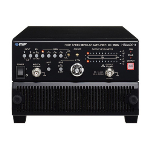
NF HSA42012 User manual

NF Corporation
HIGH SPEED BIPOLAR AMPLIFIER
HSA42011
HSA42012
HSA42014
INSTRUCTION MANUAL


DA00086378-003
HIGH SPEED BIPOLAR AMPLIFIER
HSA42011
HSA42012
HSA42014
INSTRUCTION MANUAL


HSA42011 / HSA42012 / HSA42014i
Preface
Thank you for purchasing the HSA42011 / HSA42012 / HSA42014 high speed bipolar power amplifier.
To ensure safe and proper use of this electric equipment, please read first Safety Precautions on the
following pages.
Caution Symbols Used in This Manual
The following caution symbols are used in this manual. Be sure to observe these caution
symbols and their descriptions to ensure the safety of the user and avoid damage to the
equipment.
This contains information to avoid risks in equipment handling that could result in loss of life or
bodily injury.
This contains information to avoid risks in equipment handling that could result in minor or
moderate injury to person or damage to property or the equipment.
This manual has the following chapter organization.
If reading this manual for the first time, start from 1. OVERVIEW.
1. OVERVIEW
Describes the overview, features, applications, functions, and brief operation principles.
2. PREPARATIONS BEFORE USE
Describes various cautions regarding preparations to be made before using this product.
3. PANEL FEATURES AND BASIC OPERATIONS
Describes features, behavior, and basic operation of panel knobs. Read this chapter while
operating the device.
4. ADVANCED OPERATIONS
Describes advanced operations.
5. TROUBLESHOOTING
Describes error messages and countermeasures to be taken when a failure is likely to have
occurred.
6. MAINTENANCE
Describes how to store, re-pack, and transport the device, how to run the performance test,
and so on.
7. SPECIFICATIONS
Describes the specifications including functions and performance.
!CAUTION
!
WARNING

HSA42011 / HSA42012 / HSA42014ii
Safety Precautions
To ensure safe use, be sure to observe the following warnings and cautions.
NF Corporation shall not be held liable for damages that arise from a failure to observe these warnings
and cautions.
This product is a Class 1 product (with protective conductor terminal) that conforms to the JIS and IEC
insulation standards.
Be sure to observe the contents of this instruction manual.
The instruction manual contains information for the safe operation of the product.
Be sure to read the information first before using the product.
All the warnings in the instruction manual are intended for preventing risks that may lead to serious
accidents. Ensure to obey them.
Be sure to ground the product.
This product uses a line filter and must be grounded to avoid the risk of electric shock.
To prevent electric shock, be sure to safely implement grounding so that the ground resistance is
100 Ωor less.
This product is automatically grounded when its 3-prong power supply plug is connected to a
3-prong power outlet with a protective-ground contact.
This product does not come with a 3-prong to 2-prong conversion adapter. When using a separately
sold 3-prong to 2-prong conversion adapter, be sure to connect the grounding wire of the adapter to
the grounding terminal next to the outlet.
Check the power supply voltage.
This product operates on the power supply voltage indicated in Grounding and Power Supply
Connection in this instruction manual.
Prior to connecting the power supply, check that the voltage of the power supply matches the rated
power supply of the product.
If you notice anything strange
If this product emits smoke, an unusual smell, or abnormal noise, immediately power it off and stop
using it.
If such an anomaly occurs, prevent anyone from using this product until it has been repaired, and
immediately report the problem to NF Corporation or one of our representatives.
Do not operate in an explosive atmosphere.
An explosion or other such hazard may result.
Do not remove the cover.
The product may contain high-voltage parts. Never remove the cover.
Even when the inside of this product needs to be inspected, do not touch the inside. All such
inspections are to be performed by service technicians designated by NF Corporation.
Do not modify this product.
Never modify the product. Modification to the product may pose a new risk. We may refuse the
repair of a modified product.

HSA42011 / HSA42012 / HSA42014iii
Avoid output voltage electric shock
The maximum output of the HSA42011 / HSA42012/ HSA42014 is ±75 V.
Make every effort to avoid an electric shock.
Directly touching the output or changing cable connections while output is on may cause electrical
shock.
Ensure that water does not get into this product.
Using the product in wet condition may cause electric shock and fire. When water etc. get into the
product, immediately power it off, and contact NF Corporation or one of our representatives.
If lightning occurs, power off and disconnect this product.
A lightning may cause an electric shock, a fire and a failure.
Safety-related symbols
The general definitions of the safety-related symbols used on this product and in the instruction
manual are provided below.
Instruction Manual Reference Symbol
This symbol is displayed to alert the user to potential danger and refer
him/her to the instruction manual.
Electric Shock Danger Symbol
This symbol indicates locations that present a risk of electric shock under
specific conditions.
Protective Ground-Terminal Symbol
This symbol identifies a pin that must be grounded to avoid an electric
shock.
Before operating the device, be sure to safely implement grounding so that
the ground resistance is 100 Ωor less.
Warning Symbol
This contains information to avoid risks in equipment handling that could
result in loss of life or bodily injury.
Caution Symbol
This contains information to avoid risks in equipment handling that could
result in minor or moderate injury to person or damage to property or the
equipment.
Other symbols
This symbol indicates the “on” position of the power switch.
This symbol indicates the “off” position of the power switch.
This symbol indicates that the external conductor of the connector is connected to
the case.
This symbol indicates that the external conductor of the connector is connected to
the signal ground.
!
CAUTION
!
WARNING
!

HSA42011 / HSA42012 / HSA42014iv
Waste disposal
To protect the environment, follow the guidelines described below for the disposal of this product.
a) Use the services of an industrial waste disposal contractor for disposal of the entire product.
b) This product does not use batteries.
c) This product does not contain mercury.

HSA42011 / HSA42012 / HSA42014v
Contents
Preface ................................................................................................................................................... ⅰ
Safety Precautions................................................................................................................................. ⅱ
1. OVERVIEW..................................................................................................................................... 1-1
1.1 General .................................................................................................................... 1-2
1.2 Features .................................................................................................................. 1-3
1.3 Applications............................................................................................................ 1-4
1.4 List of Functions .................................................................................................... 1-4
1.5 Principle of Operation ............................................................................................ 1-5
2. PREPARATIONS BEFORE USE ..................................................................................................... 2-1
2.1 Checking Before Use.............................................................................................. 2-2
2.2 Installation .............................................................................................................. 2-3
2.3 Grounding and Power Supply Connection ......................................................... 2-18
2.4 Simplified Operation Check ................................................................................. 2-19
2.5 Calibration............................................................................................................. 2-22
2.6 Radio Law ............................................................................................................. 2-23
3. PANEL FEATURES AND BASIC OPERATIONS.......................................................................................... 3-1
3.1 Panel Component Designations and Operations ................................................. 3-2
3.1.1 Front Panel .......................................................................................................... 3-2
3.1.2 Rear Panel ........................................................................................................... 3-5
3.2 Indications at Power-on and Initialization ............................................................ 3-8
3.3 I/O Terminals ........................................................................................................... 3-8
3.3.1 Input Connector: A (front)/B (rear) ..................................................................... 3-8
3.3.2 Output Connector (Main output)......................................................................... 3-9
3.3.3 Monitor Output Connector .................................................................................3-11
3.3.4 External Control I/O Connector .........................................................................3-11
3.4 I/O Connection ...................................................................................................... 3-13
3.4.1 Signal Generator ............................................................................................... 3-13
3.4.2 Signal Cords ...................................................................................................... 3-14
3.4.3 Load ................................................................................................................... 3-14
3.5 Examples of Basic Operations ............................................................................ 3-14
3.5.1 Input Selection and Input Impedance Selection .............................................. 3-14
3.5.2 Output Voltage Adjustment............................................................................... 3-15
3.5.3 Fine Output Offset Adjustment......................................................................... 3-15
3.5.4 DC Bias Addition ............................................................................................... 3-16
3.5.5 Output Polarity Switching................................................................................. 3-16
3.5.6 Output Voltage Monitoring................................................................................ 3-17
3.5.7 Output on/off Control........................................................................................ 3-18
3.6 Setting at Power-on .............................................................................................. 3-18
4. ADVANCED OPERATIONS............................................................................................................. 4-1
4.1 Maximum Output Current and Operation Range .................................................. 4-2
4.2 Increasing of Output Voltage by Balanced Output............................................... 4-5
5. TROUBLESHOOTING .................................................................................................................... 5-1
5.1 Error Messages....................................................................................................... 5-2
5.1.1 Errors at Power-on .............................................................................................. 5-2
5.1.2 Errors Related to the Protection Function......................................................... 5-3
5.2 When Fault Symptoms Are Observed ................................................................... 5-5
Page

Contents
HSA42011 / HSA42012 / HSA42014vi
6. MAINTENANCE.............................................................................................................................. 6-1
6.1 Introduction ............................................................................................................ 6-2
6.2 Daily Maintenance .................................................................................................. 6-3
6.3 Storage, Repacking, and Transportation .............................................................. 6-4
6.4 Performance Testing .............................................................................................. 6-5
6.4.1 Measurement of Maximum Output Voltage (AC) ................................................ 6-7
6.4.2 Measurement of Maximum Output Voltage (DC) ................................................ 6-8
6.4.3 Measurement of Frequency Characteristics ...................................................... 6-9
6.4.4 Measurement of Gain Accuracy.........................................................................6-11
6.4.5 Measurement of Sine Wwave Distortion Ratio................................................. 6-12
6.4.6 Measurement of Bias-Added Voltage ............................................................... 6-14
7. SPECIFICATIONS .......................................................................................................................... 7-1
7.1 Input ........................................................................................................................ 7-2
7.2 Output ..................................................................................................................... 7-3
7.3 Monitor Output........................................................................................................ 7-4
7.4 Output LED Meter ................................................................................................... 7-4
7.5 Protection Function................................................................................................ 7-4
7.6 External Control I/O................................................................................................ 7-5
7.7 Output On/Off Control ............................................................................................ 7-5
7.8 Setting at Power-on ................................................................................................ 7-6
7.9 Power Input ............................................................................................................. 7-6
7.10 Withstand Voltage, Insulation Resistance ............................................................ 7-6
7.11 Safety, EMC, and RoHS .......................................................................................... 7-6
7.12 Operating Environment .......................................................................................... 7-7
7.13 External Dimensions and Weight .......................................................................... 7-8
7.14 Option...................................................................................................................... 7-8
7.15 Output Voltage / Current Range............................................................................. 7-9
7.16 External Dimensions ............................................................................................ 7-11

HSA42011 / HSA42012 / HSA42014vii
Figures
Figure 1-1. Block Diagram .............................................................................. 1-5
Figure 2-1. Rack mount bracket assembly diagram (EIA for HSA42011)......... 2-6
Figure 2-2. Rack mount bracket assembly diagram (JIS for HSA42011) ......... 2-7
Figure 2-3. Rack mount bracket assembly diagram (EIA for HSA42012)......... 2-8
Figure 2-4. Rack mount bracket assembly diagram (JIS for HSA42012)......... 2-9
Figure 2-5. Rack mount bracket assembly diagram (EIA for HSA42014)....... 2-10
Figure 2-6. Rack mount bracket assembly diagram (JIS for HSA42014)....... 2-11
Figure 2-7. Rack mount bracket dimensions (EIA for HSA42011) ................. 2-12
Figure 2-8. Rack mount bracket dimensions (JIS for HSA42011).................. 2-13
Figure 2-9. Rack mount bracket dimensions (EIA for HSA42012) ................. 2-14
Figure 2-10. Rack mount bracket dimensions (JIS for HSA42012)................ 2-15
Figure 2-11. Rack mount bracket dimensions (EIA for HSA42014) ............... 2-16
Figure 2-12. Rack mount bracket dimensions (JIS for HSA42014)................ 2-17
Figure 2-13. Standard Connection Diagram .................................................. 2-20
Figure 3-1. HSA42011 Front Panel ................................................................. 3-2
Figure 3-2. HSA42012 Front Panel................................................................. 3-3
Figure 3-3. HSA42014 Front Panel................................................................. 3-4
Figure 3-4. HSA42011 Rear Panel.................................................................. 3-5
Figure 3-5. HSA42012 Rear Panel ................................................................. 3-6
Figure 3-6. HSA42014 Rear Panel ................................................................. 3-7
Figure 3-7. How to Remove and Attach the BNC Cover ................................ 3-10
Figure 3-8. External Control I/O.................................................................... 3-12
Figure 3-9. Example for I/O Control by Using External Switch ..................... 3-12
Figure 3-10. Basic Connection Diagram ....................................................... 3-13
Figure 3-11. CAL Position of Control for Fine Adjustment (VAR) ................... 3-15
Figure 3-12. Center Position of Offset Fine Adjustment ................................ 3-15
Figure 4-1. HSA42011 Operation Range......................................................... 4-2
Figure 4-2. HSA42012 Operation Range ........................................................ 4-3
Figure 4-3. HSA42014 Operation Range ........................................................ 4-3
Figure 4-4. Current Waveform Asymmetric with Regard to Polarity ................. 4-4
Figure 4-5. Connection of Two Units............................................................... 4-5
Figure 6-1. Air Filter Cleaning Procedure........................................................ 6-3
Figure 6-2. Measurement of Maximum Output Voltage (AC) ........................... 6-7
Figure 6-3. Measurement of Maximum Output Voltage (DC) ........................... 6-8
Figure 6-4. Measurement of Frequency Characteristics................................ 6-10
Figure 6-5. Measurement of Sine Wave Distortion Ratio............................... 6-13
Figure 6-6. Measurement of Bias-Added Voltage.......................................... 6-14
Figure 7-1. Ambient Temperature / Humidity Ranges ...................................... 7-7
Page

Figures
HSA42011 / HSA42012 / HSA42014viii
Figure 7-2. HSA42011 Output Voltage / Current Range .................................. 7-9
Figure 7-3. HSA42012 Output Voltage / Current Range................................ 7-10
Figure 7-4. HSA42014 Output Voltage / Current Range................................ 7-10
Figure 7-5. HSA42011 External Dimensions ................................................. 7-11
Figure 7-6. HSA42012 External Dimensions................................................. 7-12
Figure 7-7. HSA42014 External Dimensions................................................. 7-13

HSA42011 / HSA42012 / HSA42014ix
Tables
Table 1-1. List of Functions ................................................................................................................... 1-4
Table 2-1. Required Measuring Instruments ........................................................................................ 2-19
Table 2-2. Panel Setting for Operation Check ..................................................................................... 2-20
Table 3-1. List of External Control I/O Connector Pins .........................................................................3-11
Table 3-2. List of DIP Switch Settings ................................................................................................. 3-19
Table 5-1. Diagnosis Performed at Power-on ........................................................................................ 5-2
Table 5-2. Errors Related to Protection Function (1/2)........................................................................... 5-3
Table 5-3. Errors Related to Protection Function (2/2)........................................................................... 5-4
Table 5-4. When Fault Symptoms Are Observed (1/2) ........................................................................... 5-5
Table 5-5. When Fault Symptoms Are Observed (2/2) ........................................................................... 5-6
Table 6-1. Judgment of HSA42011 / HSA42012 / HSA42014 Performance.......................................... 6-15
Page


HSA42011 / HSA42012 / HSA420141-1
1. OVERVIEW
1.1 General ............................................................... 1-2
1.2 Features .............................................................. 1-3
1.3 Applications......................................................... 1-4
1.4 List of Functions .................................................. 1-4
1.5 Principle of Operation .......................................... 1-5

1.1 General
HSA42011 / HSA42012 / HSA420141-2
1.1 General
This product is a wideband, high-speed bipolar power amplifier with 1 MHz bandwidth capable of
bipolar output of an output voltage and current.
Constant voltage (CV) output characteristics are supported, and the rated output voltage and
current are ±75 V and 1.06 Arms for HSA42011, 2.12 Arms for HSA42012 and 4.24 Arms for
HSA42014, respectively.
Since this product performs bipolar output, the output voltage and current supply ranges over all
four quadrants. A general DC power supply can supply only positive current (source current) in the
case of positive voltage output. However, this product can supply both positive and negative
(source and sink) current. This product can be used with DC, so that an offset waveform or a
waveform asymmetric with regard to polarity can also be amplified.

1.2 Features
HSA42011 / HSA42012 / HSA420141-3
1.2 Features
Wideband, high speed, and large amplitude
This product has frequency bandwidth from DC to 1 MHz and a slew rate as high as 475 V/
s or more,
and still can output a maximum amplitude of 150 Vp-p.
Low output impedance
Since the output impedance is low, this product can drive loads at a constant voltage without
depending on the load impedance.
HSA42011 output impedance: [ 0.19 + 0.0155 f × (1 + j ) ] or less (typ.)
HSA42012 output impedance: [ 0.19 + 0.00803 f × (1 + j ) ] or less (typ.)
HSA42014 output impedance: [ 0.19 + 0.00460 f × (1 + j ) ] or less (typ.)
Gain setting function
A gain can be set by fixed settings ×1, ×10, ×20, ×50 and variable settings ×1 to 3.
Output polarity switching function
A switch is provided to enable this product to be switched for use as an in-phase amplifier or a
reversed-phase amplifier.
Fine output offset adjustment / DC bias setting function
DC offset can be finely adjusted. Moreover, DC voltage can be superposed on the output with the DC
bias setting function.
Protection function
This product protects against output overload and also protects against power supply faults, abnormal
internal temperatures, and so forth.
Output monitor function
This product enables output voltage monitoring based on a monitor ratio of 1/100 (BNC connector
output), and also enables output voltage/current checking (average value indication) with LED meters.
Output on/off function
Output on/off control can be exercised by using the front panel switch or an external control.
Moreover, an output state (output off or output on) at power-on time can be selected using the DIP
switch on the rear panel.
Support of worldwide power supply input voltages, Provided input power factor
improvement function
A voltage range from 100 to 230 VAC 10% is supported. The input power factor correction (PFC)
function is provided.

1.3 Applications
HSA42011 / HSA42012 / HSA420141-4
1.3 Applications
For testing and characteristics analysis liquid crystals and so forth
For testing and characteristics analysis of micro actuators and so forth
For use as a booster amplifier for signal generators such as the WF series of NF
Corporation
For use as a power supply for capacitor ripple current testing
For use as an actuator driver
For characteristics testing of diodes and semiconductors such as SCR
For characteristics testing of relays and switches
For use as a power supply for testing in an inspection line for various components
1.4 List of Functions
The table below indicates the major functions of this product.
Table 1-1. List of Functions
Function Description
Input Input on/off switching Two independent inputs. Two inputs added when
two are on.
Input impedance switching 50 /10 k Two batch-switched inputs.
Output
Output on/off switching
Fine DC offset tuning ±0.5 V
DC bias setting Settable to ±75 V or more.
Settable to on/off.
Gain setting Fixed:
1,
10,
20,
50
Variable: 1 to 3
Output polarity switching In-phase or reversed-phase
Overload protection and
indication
Monitor
Output voltage monitoring BNC output, monitor ratio 1:100
Monitor Output LED meter 0 to 100% levels of output voltage and current are
displayed with 11LEDs respectively
Other To be set at power-on time Output on/off, gain, and so forth

1.5 Principle of Operation
HSA42011 / HSA42012 / HSA420141-5
1.5 Principle of Operation
This product consists of preamplifier block, power amplifier block, and power supply block. "Figure 1-1.
Block Diagram" shows the block diagram of this product.
The preamplifier block is a wideband operational amplifier. It provides the gain tuning function, input
impedance switching function, two-input addition function, offset tuning function, and bias addition
function.
The power amplifier block performs power amplification and has protection functions.
The power supply block consists of the internal power supply block of this product, and the DC power
supply block for the power amplifier.
LINE
INPUT A
50Ω10kΩ
INPUT B
50Ω10kΩ
LINE
FILTER DCPS
FIXED GAIN VAR GAIN
|
INVERT
ON
OFF
OFFSET
BIAS POWER AMP
V METER
I METER
OUTPUT
FRONT
OUTPUT
REAR
MONITOR
VDD
SUB
PRE-AMP
Figure 1-1. Block Diagram

This manual suits for next models
2
Table of contents
Other NF Amplifier manuals
