NF DF 1906 User manual

NF Corporation
DIGITAL FUNCTION GENERATOR
DF
1906
INSTRUCTION MANUAL


DIGITAL FUNCTION GENERATOR
DF
1906
INSTRUCTION MANUAL
DA00057652-001

Trademarks
National Instruments is a registered trademark of National Instruments Corporation
in the United States.
Other company names and product names used in this instruction manual may be
trademarks or registered trademarks of their respective companies.

DF1906
i
Preface
Thank you for purchasing our "DF
1906 Digital Function Generator".
Please read "Safety Precautions" on the next page first to ensure the product is used in a correct and
safe manner.
■Caution Symbols Used in This Manual
The following caution symbols are used in this manual. The instructions of these caution symbols shall
be observed to ensure the equipment operator’s safety and prevent damage to the equipment.
This contains information to avoid electric shock and other risks when handling the
equipment that could result in the death or bodily injury of the operator.
This contains information to avoid damage to the equipment when handling the
equipment.
● This manual consists of the following chapters.
When you use this equipment for the first time, start from Chapter 1.
1. Overview
This chapter provides an overview and describes the features, applications, functions, and simple
operation principles of this product.
2. Preparation Before Use
This chapter describes the important preparations before installation and operation.
3. Explanation of Panels and Basic Operations
This chapter describes the functions/operations and basic operations of each panel part.
Please read this chapter while operating the equipment.
4.Advanced Operations
This chapter describes a wider range of operations.
5. USB Interface
This chapter describes the remote control via USB.
6. Troubleshooting
This chapter describes how to deal with error messages and trouble.
7. Maintenance
This chapter describes the storage, repacking, and transportation as well as how to test the
performance.
8. Specifications
This chapter describes the specifications (functions and performance).
!
WARNING
!
CAUTION

DF1906
ii
──── Safety Precautions ────
To ensure safe use, be sure to observe the following warnings and cautions.
NF Corporation shall not be held liable for damages that arise from a failure to observe these warnings
and cautions.
This product is a Class I device (with protective conductor terminal) that conforms to the IEC
insulation standards.
● Be sure to observe the instructions in this instruction manual.
This instruction manual contains information for the safe operation and use of this product.
Be sure to read this information first before using this product.
All the warning items contained in this instruction manual are intended for preventing
risks that may lead to serious accidents. Be sure to observe them.
● Be sure to perform the grounding.
To prevent electric shock, be sure to connect the product to an earth ground to ensure the
ground resistance is 100 ohms or less.
This product is automatically grounded by connecting a 3-pin power plug to a power outlet
with a protective ground contact.
● Check the power supply voltage.
This product operates at a power supply voltage described in "Grounding and Power
Connection" of this instruction manual.
Before connecting to the power outlet, check that the voltage of the power outlet matches
the rated power supply voltage of the product.
● If you find something strange
If this product emits smoke, abnormal smell, or abnormal noise, immediately stop use and
disconnect the power cord.
If such a problem occurs, make sure that nobody can use the product until it has been
repaired, and immediately report the problem to NF Corporation or one of our agents.
●Do not use the product in a gaseous atmosphere.
This may pose a risk of explosion or other danger.
●Never remove the cover.
There are high voltage parts inside this product. Never remove the cover.
Even when the inside of this product needs to be inspected, do not touch the inside. All
such inspections are to be performed by service technicians authorized by
NF Corporation.
Safety Precautions
DF1906
iii
!
●Do not modify this product.
Never modify the product. Modification of the product could cause an unexpected risk. NF
Corporation may refuse to repair a modified product that has failed.
● Safety symbols
The general definitions of the safety symbols used on the product body and in the
instruction manual are provided below.
Instruction manual reference symbol
This notifies the user of a potential hazard and is displayed where the user must
refer to the instruction manual.
Electric shock hazard symbol
This symbol is displayed where there is a risk of electric shock under specific
conditions.
Warning symbol
This contains information to avoid electric shock and other risks when
handling the equipment that could result in the death or bodily injury of the
operator.
Caution symbol
This contains information to avoid damage to the equipment when handling
the equipment.
●Other symbols
Indicates the ON position of the power switch.
Indicates the OFF position of the power switch.
Indicates that the external conductor of the connector is connected to the case.
!
CAUTION
!
WARNING

DF1906
- iv -

DF1906
- v -
Table ofContents
Page
1.Overview.......................................................................................................................1-1
1.1 Features......................................................................................................................1-2
1.2 Applications.................................................................................................................1-2
1.3 Function List ...............................................................................................................1-3
1.4 Operating Principle .....................................................................................................1-4
2.Preparation Before Use...............................................................................................2-1
2.1 Checking Before Use..................................................................................................2-2
2.2 Installation...................................................................................................................2-3
2.3 Grounding and Power Connection..............................................................................2-4
2.4 Simplified Operation Check........................................................................................2-5
2.5 Calibration...................................................................................................................2-6
3.Explanation of Panels and Basic Operations............................................................3-1
3.1 Panel Part Names and Operations.............................................................................3-2
3.2 Display at Power On and Initial Settings ....................................................................3-7
3.2.1 Before Powering On...........................................................................................3-7
3.2.2 Display at Power On...........................................................................................3-8
3.2.3 Initial Settings.....................................................................................................3-8
3.3 I/O Connector ...........................................................................................................3-10
3.3.1 Output Connector .............................................................................................3-10
3.3.2 Input Connector................................................................................................3-13
3.4 I/O Connection..........................................................................................................3-14
3.5 Basic Operations ......................................................................................................3-15
3.5.1 Display..............................................................................................................3-15
3.5.2 Set Numeric Value............................................................................................3-15
3.5.3 Select Setting Value .........................................................................................3-16
3.5.4 Set Frequency ..................................................................................................3-16
3.5.5 SetAmplitude and DC Offset............................................................................3-17
3.5.6 Select Waveform ..............................................................................................3-18
3.5.7 Select Oscillation Mode....................................................................................3-18
3.5.8 Select Output On/Off ........................................................................................3-19

Table of Contents
DF1906
- vi -
4.Advanced Operations..................................................................................................4-1
4.1 Symmetry and Duty Ratio...........................................................................................4-2
4.1.1 Set Symmetry (Ramp Wave)..............................................................................4-2
4.1.2 Set Duty Ratio (Square Wave)...........................................................................4-2
4.2 Oscillation Mode-related Settings...............................................................................4-3
4.2.1 Set Mark Wave Number .....................................................................................4-3
4.2.2 Set Space Wave Number ...................................................................................4-3
4.2.3 Select SYNC OUT Function ...............................................................................4-4
4.2.4 Set Phase ...........................................................................................................4-4
4.2.5 Select TRIG IN Effective Polarity (Trigger Oscillation).......................................4-5
4.2.6 Select TRIG IN Effective Polarity (Gate Oscillation)...........................................4-5
4.3 Special Menu ..............................................................................................................4-6
4.3.1 Setting Memory ..................................................................................................4-6
4.3.2 Select Output at Power On.................................................................................4-7
4.3.3 Select Load.........................................................................................................4-7
4.3.4 Set by High Level/Low Level..............................................................................4-8
5.USB Interface................................................................................................................5-1
5.1 Preparation Before Use..............................................................................................5-2
5.2 Command List.............................................................................................................5-3
5.3 Explanation of Commands..........................................................................................5-6
5.3.1 Language Overview............................................................................................5-6
5.3.1.1 Subsystem Commands...............................................................................5-6
5.3.1.2 Path Separator ...........................................................................................5-6
5.3.1.3 Command String Simplification ..................................................................5-6
5.3.1.4 Suggestion Keyword...................................................................................5-7
5.3.2 Detailed Explanation of Commands ...................................................................5-7
5.4 Command Tree .........................................................................................................5-15
5.5 Status System...........................................................................................................5-16
5.5.1 Status Byte Resister .........................................................................................5-17
5.5.2 Standard Event Status Register........................................................................5-18
5.6 Notes for Programming.............................................................................................5-19
6.Troubleshooting...........................................................................................................6-1
6.1 Error Message ............................................................................................................6-2
6.1.1 Power-On Errors.................................................................................................6-2
6.1.2 Errors of Remote Control via USB .....................................................................6-2
6.2 Troubleshooting ..........................................................................................................6-3

Table of Contents
DF1906
- vii -
7.Maintenance..................................................................................................................7-1
7.1 Preface .......................................................................................................................7-2
7.2 Daily Maintenance ......................................................................................................7-2
7.3 Storage, Repacking, and Transportation ....................................................................7-2
7.4 How to Check Version Number...................................................................................7-3
7.5 Performance Test........................................................................................................7-3
7.5.1 Frequency Accuracy Test ...................................................................................7-4
7.5.2 Amplitude Frequency Characteristic Test...........................................................7-4
7.5.3 Sine Wave Distortion Test ..................................................................................7-4
7.5.4 Square Wave Duty Ratio ....................................................................................7-4
7.5.5 Amplitude Accuracy Test ....................................................................................7-5
7.5.6 DC Offset Accuracy Test.....................................................................................7-5
7.6 Calibration...................................................................................................................7-6
8.Specifications...............................................................................................................8-1
8.1 Waveform and Output Characteristics........................................................................8-2
8.2 Output Voltage............................................................................................................8-4
8.3 Other Functions ..........................................................................................................8-5
8.4 Details of Initialization.................................................................................................8-7
8.5 General Specifications................................................................................................8-8

DF1906
- viii -
Figures and Tables
Page
Figure 1-1 Block Diagram··················································································· 1-4
Figure 3-1 Front Panel······················································································· 3-3
Figure 3-2 Rear Panel ······················································································· 3-5
Figure 3-3 FUNCTION OUT ···············································································3-10
Figure 3-4 SYNC OUT ······················································································3-11
Figure 3-5 TRIG IN··························································································3-13
Figure 3-6 Display Panel···················································································3-15
Figure 5-1 Command Tree·················································································5-15
Figure 5-2 Status System ··················································································5-16
Figure 8-1 External Dimensions Diagram······························································· 8-9
Table 2-1 Configuration List ··············································································· 2-2
Table 3-1 Initial Settings····················································································· 3-9
Table 5-1 DF
1906 Command List········································································· 5-3
Table 5-2 Common Commands············································································ 5-4
Table 5-3 Definition of Status Byte Register····························································5-17
Table 5-4 Definition of Standard Event Status Register··············································5-18

DF1906
1-1
1.Overview
1.1 Features····························································· 1-2
1.2 Applications························································· 1-2
1.3 Function List························································· 1-3
1.4 Operating Principle ················································ 1-4

1.1 Features
DF1906
1-2
1.1 Features
The "DF
1906 Digital Function Generator" is a function generator based on a direct digital
synthesizer (DDS), which is small, light, and low-priced but features high accuracy and sophisticated
functionality.
・Oscillation frequency:0.1 mHz to 2 MHz, setting resolution: 0.1 mHz. Frequency accuracy: ±25
ppm.
・Even if the frequency is changed, the phase is continuous and the waveform is not cut off.
・Maximum output voltage: 10 Vp-p/open, ±5 V/open. DC offset up to ±5 V/open can be
superimposed.
・When the amplitude is changed, no unexpected voltage is generated. The waveformcan bechangedwithout
being cut offfrom 0 to the maximum amplitude.
・In addition to the 4 standard waveforms: Sine wave, square wave, ramp wave, and DC, 4 arbitrary
waves can also be output.
・The duty ratio can be changed for the square wave. The symmetry can be changed for the ramp wave.
・Waveform data is set via a USB connection for arbitrary waveforms.
・Awealth of oscillation modes are available.
・Continuous oscillation
・Burst oscillation
・Trigger oscillation
・Gate oscillation
・Main parameters can be read at a glance on a 40-digit x 2-line LCD display panel.
・Almost all settings can be remote controlled via USB.
1.2 Applications
・Measurement of filters, in particular of those with steep characteristics.
・Signal source of audio equipment and pulse motor using the burst oscillation mode
・Signal source of an automated measurement system
・Oscillator for various experiments

1.3 Function List
DF1906
1-3
1.3 Function List
The following shows a function tree.
Output
Output On/Off
Select Output On/Off State at Power On
Return to State at Last Power Off
Always On
Always Off
Oscillation Mode
Continuous Oscillation
Burst Oscillation
Mark Wave Number
Space Wave Number
Select SYNC OUT Function
Phase
Trigger Oscillation
Select Trigger Input Polarity
Mark Wave Number
Select SYNC OUT Function
Phase
Gate Oscillation
Select Trigger Input Polarity
Select SYNC OUT Function
Phase
Waveform
Sine Wave
Ramp Wave
Symmetry
Square Wave
Duty Ratio
Arbitrary Waveform
Select Waveform (1 to 4)
DC Generation
Voltage
Amplitude
Vp-p
Vrms (for Sine Wave only)
DC Offset
High Level
LowLevel
Select Output Load Setting Memory
/Open Select (1 to 20)
/50ΩSave/Read
Frequency Clear
MHz
kHz
Hz Remote Control
mHz Display Serial Number
1.4 Operating Principle
DF1906
1-4
1.4 Operating Principle
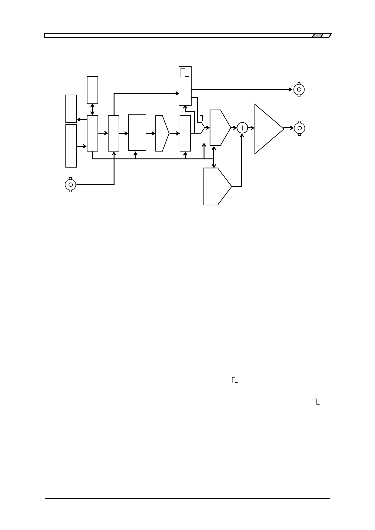
Figure 1-1 Block Diagram
・CPU performs analog control, such as display panel control, panel key and dial process, USB
remote control process, DDS control, amplitude, and DC offset.
・DDS (Direct Digital Synthesizer) generates digital data at the set frequency.
・Waveform Memory converts the digital data from the DDS to standard waveform or arbitrary
waveform data.
The waveform data is set from the CPU. The update rate of waveform data is approx. 6.872 MHz.
・The waveform data acquired in this way is converted to an analog signal by the D/Aconverter.
・LPF (Low Pass Filter) smoothens a staircase waveform output by the D/Aconverter.
The analog bandwidth (at the -3dB) for arbitrary waveforms and sine wave and ramp wave in the
burst/trigger/gate oscillation mode is approx. 650 kHz.
・For a square wave at a duty ratio of 50% and at a frequency of 10 kHz or more, a low jitter square
wave is obtained by generating a sine wave by the Waveform Memory-D/A Converter-LPF and
converting it to a square wave by an analog comparator in the generator.
・For a square wave at a duty ratio of other than 50% or at a frequency of less than 10 kHz, a logic
signal with a duty variable pulse generated by the DDS is converted to a square wave by the
generator. This includes a one-clock (approx. 150 ns) jitter of the DDS.
・The amplitude is set in the amplitude controller. The DC generator generates a DC offset, which is
added and amplified in the output amplifier to output a signal.
Generation
Amplitude
Control
Output
Amplifier
Display
Key Dial
Waveform
Memory
TRIG IN
S
YNC OUT
FUNCTION
OUT
Others
DC Offset
USB
CPU
LPF
D/A
DDS

DF1906
2-1
2.Preparation Before Use
2.1 Checking Before Use··································· 2-2
2.2 Installation ················································ 2-3
2.3 Grounding and Power Connection···················· 2-4
2.4 Simplified Operation Check ··························· 2-5
2.5 Calibration ················································· 2-6

2.1 Checking Before Use
DF1906
2-2
2.1 Checking Before Use
■Safety Check
Please read "Safety Precautions" at the beginning of this instruction manual before using the
DF
1906 to ensure safety.
Furthermore, before connecting to the power supply, read "2.3 Grounding and Power Connection"
to ensure safety.
■Things to Check when Unpacking
First of all, check that the product has not been damaged during transport.
Before installing the equipment, make sure that the configuration is as specified in "Table 2-1
Configuration List".
Table 2-1 Configuration List
There are high voltage parts inside this equipment. Never remove the cover.
No one except trained service technicians who have knowledge of hazard prevention is
permitted to check the inside of this equipment.
Main unit ····································································· 1
Power cord set ································································ 1
CD-ROM (Instruction Manual,
ARBITRARY WAVEFORM EDITOR DF
0106) ········ 1
!
WARNING

2.2 Installation
DF1906
2-3
2.2 Installation
■ Precautions
Please pay attention to the following points, otherwise the DF
1906 may be damaged.
・The DF
1906 is cooled by natural air cooling.
Install with a minimum clearance of 10 cm from the wall, etc.
・To install the DF
1906 with the rear panel facing down, be sure to raise the legs in the
upper part of the rear panel.
If it is installed with the legs not raised, an excessive force is applied to the power cord
and it may be damaged.
■ Installation Conditions
Install the DF
1906 in a place that satisfies the following temperature and humidity conditions.
Performance guarantee: +5 to +35℃, 5 to 85 %RH (Absolute humidity 1 to 25 g/m3, non-condensing)
Storage: -10 to +50℃, 5 to 95 %RH (Absolute humidity 1 to 29 g/m3, non-condensing)
Avoid installation in the following locations.
・Places exposed to direct sunlight, or places near a heat source.
・Places exposed to dust, salt, metallic powder, etc.
・Places exposed to corrosive gas, moisture, oil smoke, etc.
・Places exposed to vibration.
・Places near intense magnetic or electric field sources.
・Places near pulse noise sources.
When output accuracy is important, allow the equipment to warm up for at least 2 hours before use.
Keep the power cord of the DF
1906 or other equipment away from the signal cable. If the power cord
and signal cable are installed close to each other, a malfunction may occur.
Pay attention to the cable placement particularly when mounting the DF
1906 in a rack, etc.
■ Handling of Panels and Case
The front panel of the DF
1906 is made of a polyester film. Avoid damage from contact with sharp or
hot objects.
When the panel or case needs cleaning, wipe with a soft cloth. To remove persistent stains, wipe with
a soft cloth soaked with neutral detergent and wrung out.
Do not use any organic solvents like thinner or benzene, or any chemical cleaning cloth, as they may
cause the surface finish to deteriorate, tarnish, or come off.
!
CAUTION

2.3 Grounding and Power Connection
DF1906
2-4
2.3 Grounding and Power Connection
■ Grounding
Take the following precautions to avoid risk of electric shock.
Before making connections for measurement, be sure to connect the protective ground
terminal to an earth ground.
The protective ground terminal of the DF
1906 is a grounding pin of the 3-pin power
cord.
Be sure to insert the power plug into a 3-pin power outlet with a protective ground
contact.
■ Power Supply
To prevent damage to the DF
1906, check that the voltage of the power outlet is within
the power supply voltage of the DF
1906 and then connect to the power outlet.
The DF
1906 operates from the following power outlet.
Power supply voltage range: 100 V to 240 V AC±10%, 250 V or less
Power supply frequency range: 50/60 Hz±2 Hz
The maximum power consumption is 25 VA.
Before connecting the power cord, check that the power switch is off.
When turning the power off and then back on, wait at least 5 seconds before turning the power back on.
There are high voltage parts inside this equipment. Never remove the cover.
!
WARNING
WARN
!
WARNING
!
CAUTION
Table of contents
Other NF Inverter manuals


Popular Inverter manuals by other brands

Eguana
Eguana Evolve Hub A installation manual

Baldor
Baldor STANDBY PERMANENT MOUNT SERIES Operator's manual

AEG
AEG AS-IC01-4000 installation instructions

Deye
Deye SUN-60K-G03 user manual

Mitsubishi Electric
Mitsubishi Electric FR-D700-SC-EC Safety stop function instruction manual

Sila
Sila PRO 15000MH user manual


