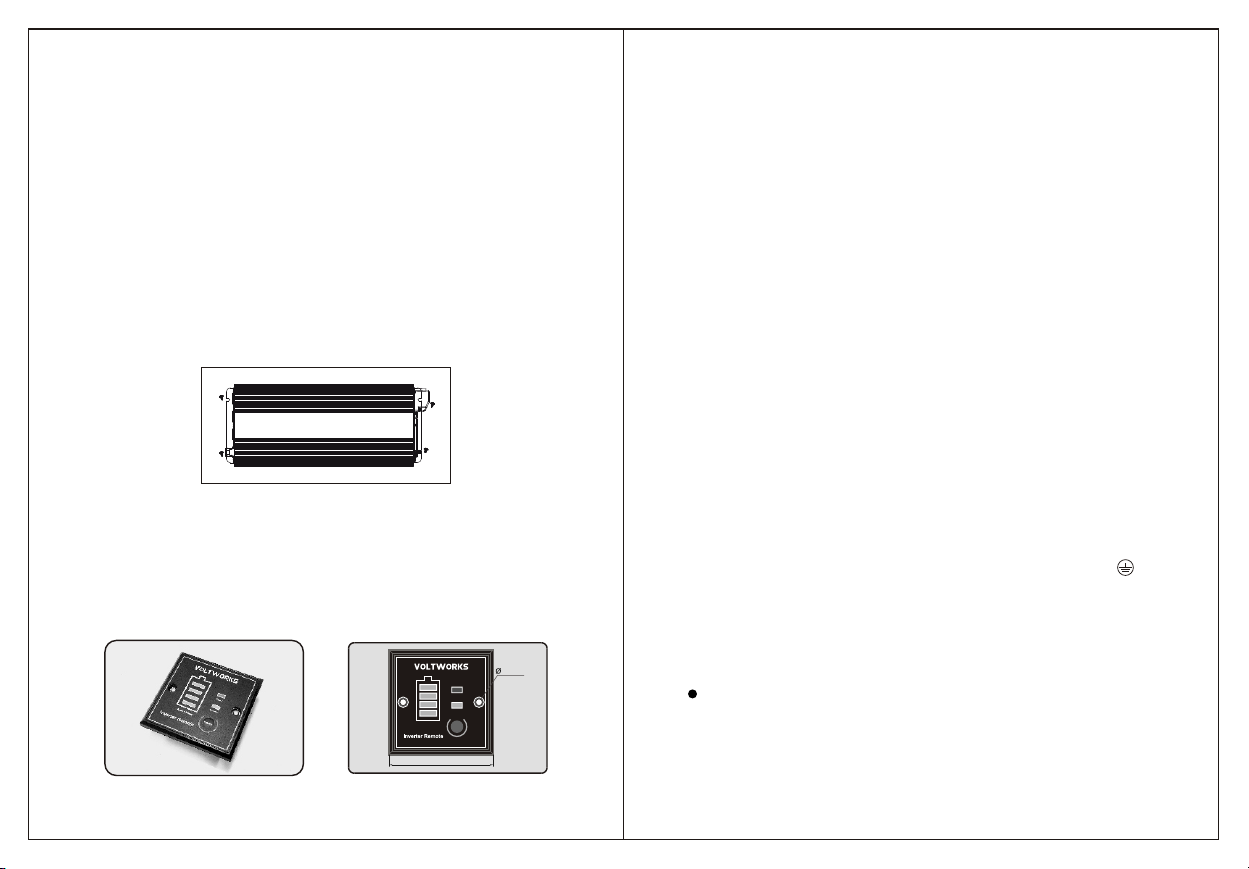
VOLTWORKS VS-4000QBR User manual

MODEL: VS-3000QBR
VS-4000QBR
1 26

Specifications
Model
Rated input Voltage
Continuous Power
Peak Power
Input VoltageRange
Over VoltageShutdown
Low VoltageShutdown
Low VoltageAlarm
Output Voltage
Frequency
Wave form
Efficiency
Over load protection
Short Circuit protection
Display
USB
No load current
Cooling fan
Storage temperature
Size (L W H)
Weight
Over heat Protection
12VDC
3000W
6000W
9.8~16VDC
16VDC
9.8VDC
10.1VDC
24VDC
3000W
6000W
19.6~32VDC
32VDC
19.6VDC
20.2VDC
12VDC
4000W
8000W
9.8~16VDC
16VDC
9.8VDC
10.1VDC
24VDC
4000W
8000W
19.6~32VDC
32VDC
19.6VDC
20.2VDC
Operating Temperature
(Automatic Recovery/
Shutdown)
VS-3000QBR VS-4000QBR
100V / 110V / 120V / 220V / 230V / 240V
AC 10% (Refer tolabel)
50Hz / 60Hz 1Hz
Pure Sine Wave
About 90%
ºF ºF149 8
3000~3300W 4000~4400W
yes
LCD
5VDC 0~2.4A 2 MAX 2.4A
32-113 ºF
14~ 113ºF
15 8 6.7 inch 20.16 8 6.7inch
15.5lbs / 7.03Kgs 21.85lbs / 9.91Kg
2A 1.2A 3A 1.5A
Thermal controlled coolingfan. It won'twork till inverter
case reaches 104 ºF only.
Remark Due to the continuous improvement of products,the technical parameters
in this manual are subject tochange without prior notice.
A. INTRODUCTION
The GIANDEL pure sine power inverter product line is used for back-up power. The
pure sine product line is ideal for sensitive equipment and provides clean power, which is
more efficient for back-up power applications. The power inverter transforms DC (direct
current) electricity into AC (alternating current) power that can be used for running a wide
variety of tools and appliances. Thisinverter is perfect for providing mobile powerin cars,
boats and work trucks. The invertercan also be utilized as a back-upsource of electricity
in the event of an electrical failure or for several off-grid applications such as camping or
in your RV.
Please read this instruction manual carefully and make sure your inverter is installed
properly before using.
B. WARNING ANDSAFETY
1. Read the manual before connectingthis inverter and keep it forfuture reference.
2. Do not put the inverterunder direct sun light or neara heating source.
3. The case of inverter willget hot when used. Do not allow flammable materials to contact
the inverter, such as clothing, sleeping bags, carpet or any other flammable materials.
The heat from the inverter can damagethese items.
4. The power inverter is designed to be used with a negative ground electrical system!
Don't use with positive ground electrical systems (the majority of modern automobiles,
RVs, trucks and boats are negativeground).
5. Do not disassemble the unit: itmay cause fire or electric shock.
6. This device should only be serviced by a qualified technician. This item does not have
any serviceable parts.
7. Prevent body contact with grounded surfaces such as pipes, radiators, ranges, and
refrigerator enclosures during installation.
8. Do not operate the inverter if under the influence of alcohol or drugs. Read warning
labels on prescriptions to determine if your judgement or reflexes are impaired while
taking drugs. If there is anydoubt, do not operate the inverter.
9. People with pacemakers should consult their physician(s) before using this product.
Electromagnetic fields in close proximity to a pacemaker could cause interference to or
failure of the pacemaker.
10. Keep the inverter well-ventilated. Do not place any objects on top of or next to the
inverter or allow anything to cover the cooling fans; doing so can cause the inverter to
overheat, causing a potential fire hazard and/or damage to the inverter. Leave
adequate ventilation space underneath the inverter as well; thick carpets or rugs can
obstruct air flow, causing theinverter to overheat.
11. Avoid unintentional starting. Be sure the switchis in the OFF position when not in use
and before plugging in any appliance.
12. Keep inverter away from children. Don't install the inverter where it is accessible to
children.
13. The power inverter will output the same AC power asutility power, please treat theAC
outlets as carefully as you wouldyour home AC outlets.Do not put anything other than
an electrical appliance into the outputterminal. It may cause shock orfire.
1.
1 26

2.
3. Assemble theremote control box
3.
C. Parts list:
Grounding
Inverter power switch
Power Indicator Fault indicator
Remote controller interface
Dual USB ports
AC outlets
AC hard wire terminals
LCD display
Thermal control cooling fan
DC input connector (+)
DC input connector (-)
(Only for VS-3000QBR)
Thermal control cooling fan
DC input connector (+)
DC input connector (-)
(Only for VS-4000QBR)
1. DC Input Side
2. AC Output side
Switc h
Powe r indicato r
Faul t indicato r
Wir e of remot e
Battery level
status
1 26

Battery Status
FAULT
POWER
ON/OFF
85mm
4.5mm
4. 5.
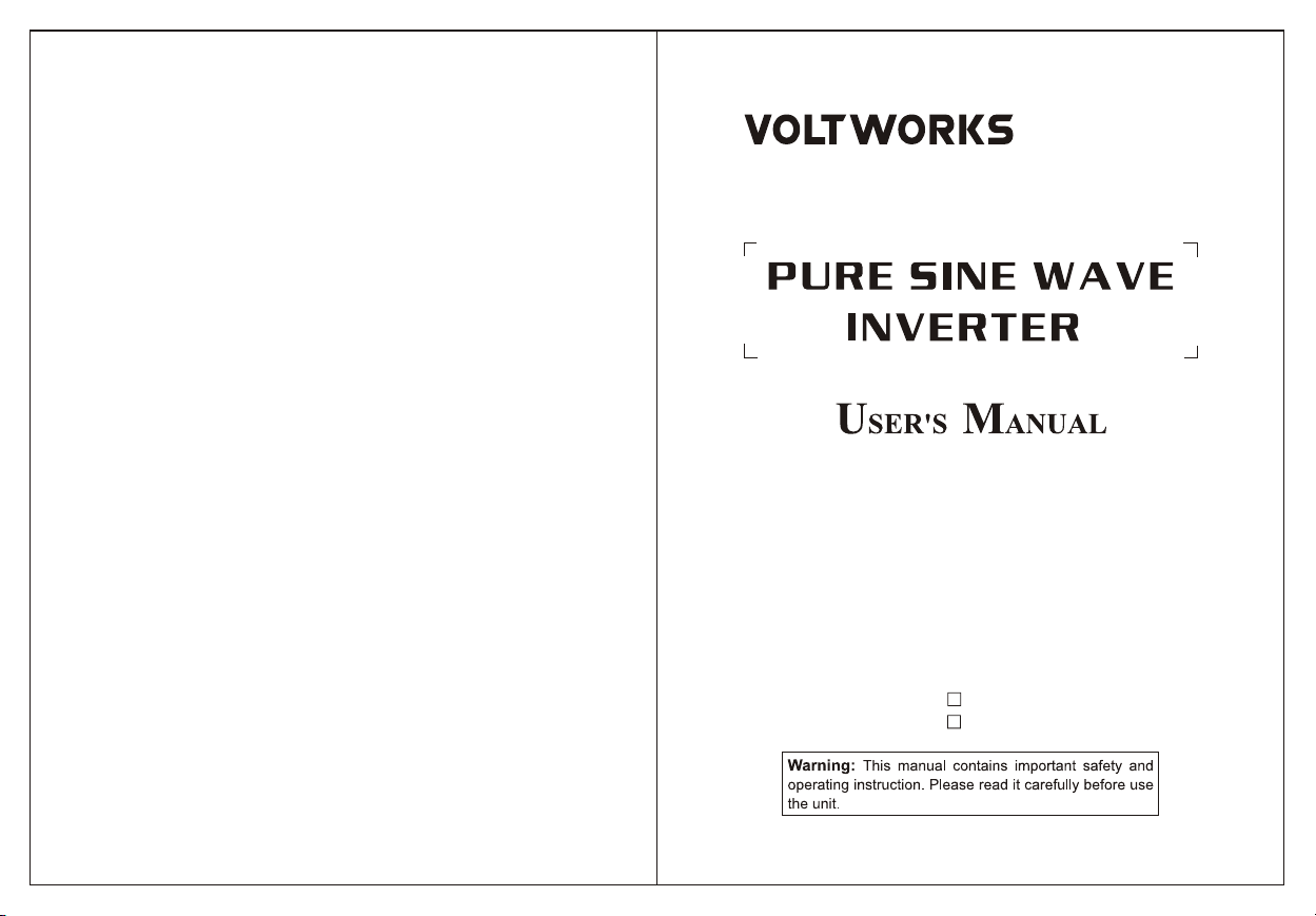
D. INVERTER INSTALLATION
Ensure there is enough space for the installation, and the location should be meet the
following requirements:
1. Water should not accessthe inverter.
2. The ambient temperature should be 32~104°F, and the preferred temperature is 50-
77°F. The lower the better inthis range of ambient temperature.
3. Do not mount the inverterupside down.
4. Allow 12 inches of space around the inverter to prevent objects from blocking the vents
and to provide enough air to circulate.
5. Do not install the inverter in an environment with high dust, saw dust residue or other
particles that may get sucked into the inverter increasing internal temperature.
6. There will be some electricalarcing or spark when the inverter connectswith the battery.
Combustible materials such as gasoline, alcohol, etc. should not be around the inverter.
7. We recommend mounting the inverter on something stable to prevent it from bouncing.
Impact shock could result in damage to your unit. Be sure to use all four mounting
screws for optimal stability. Mount in a location that can support the weight of the
inverter.
E. REMOTE CONTROLLER INSTALLATION
1) Fix the remote box on flat surface where a hole should be made, and use 2 screws to fix
it through the two mounting holes on the remote controller.
2) Or fix the remote on astandard 86X86mm(3.39x3.39 inch) power socket;
3) Connect the inverter and remote controller by wire before mounting.
Remark: Without remote controller, you can turn on the inverter by the switch on the
inverter too.
F. BATTERY
1. The battery is designed to supply the inverter with DC input voltage and the rated
voltage should be in accordance with the rated input voltage of the inverter. Any voltage
exceeding the range of the input voltageof the inverter will cause the inverterto go into
overload and could possibly damage the inverter. The battery should supply enough
current for the load. The load is the amp or watt rating of the equipment being powered
by the inverter. A small capacity battery cannot provide enough power for a large
electrical equipment. In this case, the battery will cause the inverter to go into under
voltage protection because of the load put on the battery. A simple way to calculate the
load or amps required from your battery is to divide watts of equipment by battery
voltage.
Due to the consumption of the inverter itself, the actual current will be about 10%. For
example, the voltage of lead acid battery is 12VDC, and load of the equipment is
1000W, therefore, the actual current needed from the battery is about 1000W / 12V =
83.3 amps per hour. Add 10% for efficiency loss and you get 83.3 * 1.10% = 91.6 amp
per hour needed. If you don't know the wattage of your equipment, you can figure the
wattage by multiplying AC amps by AC voltage. For example, a refrigerator is 8 AC
amps * 120 Volts AC = 960 watts. Remember, all equipment has a start-up requirement
3-5x its running wattage. In this example, 960 watts * 3 = 2880 watts needed from the
inverter so don't size your inverter too small.
2. Battery operating time depends on battery capacity and load. The formula for
operating time is: battery capacity divided by the value of the load divided by battery
voltage times 1.10%. For example, using the numbers from above, the battery
specification is 12V, 200Ah capacity and the load is 1000W. Take battery capacity
200Ah / 91.6 amps = 2.18 hours of run time if you fully deplete the battery. This is NOT
recommended. Deep cycle batteries last longer when they are only depleted to 50% of
capacity.
G. CONNECTION
1. Grounding
The power inverter has a terminal on the rear panel marked " Grounding "or " ". This
is used to connect the chassis of the power inverter to ground. The ground terminal has
already been connected to the ground wire of the AC output receptacle through the
inverter.
The ground terminal must be connected to the ground wire, which will vary depending
on where the power inverter is installed. In a vehicle, connect the ground terminal to the
chassis of the vehicle. In a boat, connect it to the boat's ground system. In a fixed
location, connect the ground terminal to earth.
2
The ground wire must be 14AWG(2.08mm )or larger,and make sure the connections
are well.
2. Battery Connection:
Before you connect the battery cables, make sure the power switch is in the off position.
Connect Red (+) battery cable to Red(+) inverter terminal. Connect Black (-) battery
1 26

6.
Output socket AC output voltage Single socket
max output current
Single socket
max output power
110~120VAC
220~240VAC
220~240VAC
220~240VAC
15A
16A
13A
10A
1500W
3000W
2500W
2000W
220~240VAC 13A 2500W
cable to Black (-) inverter terminal. Connect Red (+) battery cable to Red (+) battery
terminal. Connect Black (-) battery cable to Black (-) battery terminal. Alligator clamp
cables may be used but only to connect to the battery. Do not use clamps on inverter
terminals. Alligator clamps are not a permanent solution. You may see a spark during
connection. Do not reverse the polarity. This may damage the inverter and void
warranty.
Notice:
1) Please do all the safety precautions before connecting, and then check whether the
battery voltage comply with the inputvoltage of the inverter.
2) The cables must be bigenough to bear current, or else the inverter can not power up
a big load because of voltagereduce caused by the small cross-sectionalwire.
Refer to the below table tochoose cables accordingly.
Inverter Input
voltage Rating power Max current
of cable
Specification of wire
length 1m
12V
24V
1000W
1500W
2000W
2500W
3000W
4000W
5000W
1000W
1500W
2000W
2500W
3000W
4000W
5000W
100A
150A
200A
250A
300A
400A
500A
50A
75A
100A
125A
150A
200A
250A
2
6AWG(13.30mm)
2
4AWG(21.15mm)
2
3AWG(26.67mm)
2
2AWG(33.62mm)
2
1AWG(42.41mm)
2
0AWG(53.49mm)
2
00AWG(67.43mm)
2
9AWG(6.63mm)
2
7AWG(10.55mm)
2
6AWG(13.3 mm)
2
5AWG(16.77mm)
2
4AWG (21.15mm)
2
3AWG (26.67mm)
2
2AWG (33.62mm)
2
N 13.30mm
2
N 21.15mm
2
N 26.67mm
2
N 33.62mm
2
N 42.41mm
2
N 53.49mm
2
N 67.43mm
2
N 6.63mm
2
N 10.55mm
2
N 13.30mm
2
N 16.77mm
2
N 21.15mm
2
N 26.67mm
2
N 33.62mm
Specification of wire
length 1m
Specification of wire
length N m
2
3AWG(26.67mm )
2
1AWG(42.41mm )
2
0AWG(53.49mm )
2
00AWG(67.43mm )
2
2 1AWG(84.82mm )
2
2 0AWG(107mm )
2
2 00AWG(135mm )
2
6AWG(13.3mm )
2
4AWG(21.15mm )
2
3AWG(26.67mm )
2
2AWG(33.62mm )
2
1AWG(42.41mm )
2
0AWG(53.49mm )
2
00AWG(67.43mm )
Notice:
1. The above table is onlyfor your reference. In practice, the thick wire can be replaced by
two thin parallel wires if only the total section acreage of the wire meets the
requirements.
2. In high current, the input DC wire may produce voltage drop, therefore, the operating
voltage should be subject to the value on the terminals. If the voltage drop is too large,
it can increase the acreage of the section or reduce the length of the lead. The
recommended length of lead is less than1m.
3. Connect cathode wire of thebattery to the cathode terminal (black)on the back panel of
inverter and then connect the anode wire of the battery to the anode terminal (red) on
the inverter, and fix them.
Warnings:
1) Please wear eye patch and work clothes when working around the battery to avoid the
acid and corrosive objects harm youreyes and skin.
2) Prepare enough water and soap. In case the acid materials contact eyes or skin, clean
it by soap and water as soon as possible. If the acid materials spay to your eyes
accidentally, clean it bycold water immediately and then sent to hospital.
3) Do not put any combustible material in the location of installation for spark will result
when it is connected to the battery.
4) Keep good ventilation. The battery may produce a little inflammable gas whenit works,
so keep away from the inverterand it is better to installthem in different space.
5) Fix the connecting wire of the input DC, or it will result the over-reduction of the voltage
or over-temperature of the wire.
6) Reverse connection of the polarities or the short circuit will burn the fuse or result the
permanence damage of the internal elementsof inverter.
7) Take away the metal accouterment, such as ring or watch, when installation to avoid
the short circuit.
8) Although there is over-voltage protection, it may also cause damage of the inverter if
the input voltage is too high.
3. Connection of the ACappliance
Put the power plug of the AC appliance load into the output AC receptacle ofthe inverter
directly.
Warnings:
1. Make sure that the switches of the inverter and appliance power are in OFF position
before connection.
2. Check the power cord. If itis damaged, it should be connected afterreplacement.
3. Each outlet of the inverter has a given current rating of the manufacturer. It shall not
exceed this value during use. Otherwise, the socket may be damaged by overheating
and may cause an electric shock. The maximum output power of a single socket is
shown in the following table:
Connection of big load
For the appliances with a load more than the limit of AC socket ,please connect to the
Hard wire Terminals(if have) ,make sure the ground terminal of inverter connected with
ground terminal of appliance.
7.
1 26

8. 9.
H. SOFT START TECHNOLOGY
The soft start technology built into this inverter protects the unit from delivering too
much AC power at once by gradually increasing the AC voltage pushed out. To make
sure that you are utilizing this feature, turn on the appliance being used before turning
on the inverter. Thisis especially necessary for equipment that has an inductive load or
electrical motor
I. OUTPUT VOLTAGE & WAVEFORM
The electrical waveform output of this inverter is a pure sine wave, which has the same
quality as utility and/or domestic power This type of waveform is suitable for most
electrical devices, appliances and tools. This pure sine wave unit provides more
capabilities than modified sine wave inverters because it is a cleaner form of power.
The pure sine wave also effectivelyreduces the noise produced while using appliances.
.
.
J. LCD Display
While inverter is working, the LCD display will show Battery Status Level,Pure Sine
Wave Symbol, Input Voltage , Output Voltage ,current etc . Once the inverter is on
protection mode, the following codes willshown:
1.LO: Low voltage protection
2. HI: High voltage protection
3. OL: Overload or short-circuit protection
4. OH: overheat protection.
162.6 Volta peak
Pure Sine Wave Output
(120 VAC Model)
K. PROTECTIONS IN THE INVERTER
1. Input under-voltage alarm: When the input DC voltage is lower than 9.8V (19.6V),
the buzzer will whistle intermittently to remind that the inverter will go into the
under voltage protection.
2. Under voltage protection: The inverter will automatically shut down when the input
DC voltage is lower than 9.5V(19V). The buzzer will whistle continuously and the
green light is off, red light is on. Please turn off the inverter and use it after
recharging the battery.
3. Over voltage protection: The inverter will automatically shut down when the input
DC voltage is higher than 16V(32V). The buzzer will whistle continuously and the
green light is off, red light is on. Please turn off the inverter and adjust the input
voltage to the admissible range.
4. Overload protection: The inverter will automatically shut down when the load is
higher than the rated power. The buzzer will whistle continuously. Turn off the
inverter and resume to normal operationafter taking away the excessive load.
5. Short-circuit protection: The AC output will be automatically shut down when short
circuited. It will automatically reset afterthe problem is solved.
6. Thermal protection: The unit will get hot during operation. If the temperature is
higher than 149ºF, the inverter will automatically shut down. Then the buzzer will
whistle continuously and the green light is off, red light is on. Please turn off the
inverter, and continue using it after the temperature goes back to normal naturally.
Meanwhile find out the factors causing the fault, such as ventilation, ambient
temperature, vent, load power etc. Itcan avoid similar things from happeningagain.
**NOTE** The numbers in the parenthesis are for 24V models. In the case of over
voltage, under voltage and thermal protection, the inverter will shut down. When the
inverter is in the OFF position, theinverter doesn't consume battery current.
120
1 26

10. 11.
If the inverterstill doesn't workafter trying abovemeasures, there may
be some faultsin the circuit.Please return itto the supplierfor
maintenance.
L. Failure guidelines
No output voltage,
buzzer sounds
continuously
Incorrect output
voltage
Cannot drive the
load
1. Do not use when the battery is charging.
2. Check the rated voltage of the battery
and make sure that it is in the allowable
range of the input voltage.
1. Turn on the power switch.
2. Check the cables and make sure they
are tightly connected.
1. Use a true RMS multimeter to measure,
such as model FLUKE 177/179.
2. Try to maintain the input voltage in the
range of rated power
3. Change the battery of multimeter then
test again.
Reduce the load power, or turn on the
appliance first, then turn on the inverter.
1. The switch is off.
2. The battery lead
isn't connected well
1. RMS Multimeter
measurement error
2. The battery power
of RMS Multimeter
is low.
3. The input voltage
is too high or too low.
1. Load power is too
large, or the actual
power of the
appliance exceeds
nominal power.
2. The starting power
is larger than rated
power (such as
motor).
The internal inverter soft-start circuit will
buffer starting the appliance.
Cut off the load and let it cool naturally for
10 to 30 minutes. Restart it after it resumes
to normal temperature. The load power is
too large, reduce the total load power to the
range of rated power. Avoid blocking the
vent and improve the ventilation condition.
Reduce the ambient temperature.
No output voltage
Low input DC voltage
High input DC
voltage
Overload
Over temperature
Recharge or replace the battery
Reduce the load power.
M. WARRANTY
This product is designed using the most modern digital technology and under very
strict quality control and testing guidelines.If,however, you feel this product is not
best to resolve your concerns. If the product needs repair or replacement, make sure
to keep your receipt/invoice, as that will need to be sent back along with the package
and prepaid to VOLTWORKS. You have a full 18 months warranty from date of
purchase.
The following situations willvoid warranty:
1.The box is distorted, damaged or changed, and interior parts damaged because of
an exterior hit ordrop not reported attime of delivery.
2.Connect the DC power incorrectly reversing the polarity. 3.Dismantled or repaired
the unit byan unauthorized person.
4.The unit wasdamaged by incorrectinstallation or operating method.
To findout where to buyany of our products,you may also e-mail:
1 26
This manual suits for next models
1
Table of contents
Other VOLTWORKS Inverter manuals
Popular Inverter manuals by other brands

Haier
Haier SUPER MATCH AS35S2SF1FA-BC Service manual

MELINERA
MELINERA 48768 Operation and safety notes

Powtran
Powtran PI7500 Series user manual

Votronic
Votronic MobilPOWER SMI 300 Sinus-NVS Installation and operating manual

Zamp Solar
Zamp Solar ZS-8AW user manual

Sungrow
Sungrow SG110CX Quick installation guide

Chicago Electric
Chicago Electric 91813 instructions

Unitronics
Unitronics UMI-S0 Series Technical Specifications and Installation Guidelines

Eltek Valere
Eltek Valere THEIA S user guide

Valsi
Valsi G80MG1500KVAE Service manual

ExelTech
ExelTech MCX Installation and operation manual

Honeywell
Honeywell Q624A Product data