Eguana Evolve Hub A User manual

DO70008Rev1
Evolve Hub A
Installation Manual
For use with the Evolve ESS & Evolve LF energy storage systems

DO70008Rev1
IMPORTANT SAFETY INSTRUCTIONS
SAVE THESE INSTRUCTIONS
This manual contains important instructions for the Evolve™ Hub as part of a complete home energy storage system.
The Evolve Hub is a peripheral of the battery system, and is compatible with the Evolve ESS and Evolve LF models.
CAUTION: Hazardous Voltages! This product contains hazardous voltage and energy that may be lethal. It may only
be installed by qualified personnel who have read this manual and are familiar with its operation and hazards. The
following safety procedures should be followed:
Only connect the Evolve Hub to a compatible electrical service as defined in the model specifications.
Ensure proper electrical grounding in accordance with code requirements.
Ensure proper airflow path for active cooling.
Never operate system in a manner not described by this manual.
Only qualified personnel should service this product.
Ensure cover is securely fastened after installation is complete.
Do not attempt to operate this product if there is any physical evidence of damage to the enclosure or internal
components.
CAUTION! This product contains an AGM lead acid battery. This product must be stored indoors in an
environmentally conditioned location prior to installation, protected from rain and exposure to any hazardous
chemicals. Inspect the battery case prior to installation. Do not install and power the product if there appears to be
damage to the battery and contact your local product distributor.
Do not dispose of the system or any of the components within the cabinet. Batteries, electronics, cables, and metal
parts are recyclable. Consult your municipal waste management authority to determine required methods of
component recycling.

Contents
1 INTRODUCTION ...........................................................................................................................................................................2
1.1
A
BOUT THIS MANUAL
–
SUPPORTING DOCUMENTS
........................................................................................................2
1.2
G
LOSSARY
..............................................................................................................................................................2
1.3
I
NITIAL
I
NSPECTION OF
M
ATERIAL
L
IST
.......................................................................................................................2
1.4
S
PECIAL
T
OOLS
&
H
ARDWARE
..................................................................................................................................3
1.5
F
UNCTIONAL
O
VERVIEW
...........................................................................................................................................3
1.5.1 Grid Connected Solar plus Storage ......................................................................................................................................... 3
1.5.2 Backup Solar plus Storage ......................................................................................................................................................... 4
1.5.3 Backup Solar PV curtailment method: requency Shift Power Control ( SPC) ....................................................... 4
1.5.4 Circuit and system sizing for 100 / 125 / 150 Amp electrical panels .......................................................................... 4
1.5.5 Circuit and system sizing for 200+ Amp electrical panels .............................................................................................. 4
1.5.6 Over-sized PV systems ............................................................................................................................................................... 4
1.6
I
NTERNAL
C
OMPONENT
O
VERVIEW
............................................................................................................................5
1.6.1: Energy management controller (EMC) .................................................................................................................................. 5
2 INSTALLATION PLANNING.......................................................................................................................................................6
2.1
I
NSTALLATION CLEARANCES BETWEEN THE
E
VOLVE
H
UB AND THE BATTERY SYSTEM
.......................................................6
2.2
I
NSTALLATION CONDUIT PLAN
–
POWER AND COMMUNICATION CIRCUITS
.........................................................................7
2.3
SLD
-
AC
C
OUPLED
PV
S
YSTEM WITH
B
ACK
-
UP
P
OWER
O
PERATION
...........................................................................8
3 INSTALLATION INSTRUCTIONS .............................................................................................................................................
4 ELECTRICAL WIRING INSTRUCTIONS ...................................................................................................................................
4.1
EMC
C
ABLE
C
ONNECTION
.......................................................................................................................................9
4.2
AK1
C
ABLE
C
ONNECTION
.........................................................................................................................................9
4.3
AC
P
OWER
C
ONNECTIONS
..................................................................................................................................... 10
4.3.1 Phase Orientation in Split Phase 120/240 Systems ....................................................................................................... 10
4.3.2 Main Electrical Panel Connection ........................................................................................................................................... 11
4.3.3 Backup Panel Connection......................................................................................................................................................... 11
4.3.4 Evolve battery system: PCS Grid Port Connection ......................................................................................................... 11
4.3.5 Evolve battery sytem: PCS Load Port Connection .......................................................................................................... 11
4.4
CT
C
ONNECTIONS
................................................................................................................................................. 12
4.4.1 Main Electrical Panel CT Connections .................................................................................................................................. 12
4.4.2 Solar PV CT Connection............................................................................................................................................................ 12
4.4.3 Evolve PCS CT Connections .................................................................................................................................................... 12
4.5
12V
B
ACKUP
B
ATTERY
C
ONNECTION
.......................................................................................................................12
5 OPERATION ............................................................................................................................................................................... 13
5.1
EMC
SELECTOR SWITCH
:
EMS
A........................................................................................................................... 13
5.2
P
RE
-
STARTUP CHECKLIST
.......................................................................................................................................13
5.3
S
TARTUP
..............................................................................................................................................................13
5.4
P
OST
-
STARTUP CHECKLIST
.....................................................................................................................................13
5.5
P
ERMISSION TO OPERATE CHECKLIST
.......................................................................................................................14
6 MAINTENANCE ......................................................................................................................................................................... 14
7 TROUBLESHOOTING ............................................................................................................................................................... 14
8 TECHNICAL DATA ................................................................................................................................................................... 15
8.1
E
LECTRICAL SPECIFICATIONS
..................................................................................................................................15
8.2
W
IRE AND TORQUE RATINGS
................................................................................................................................... 15
APPENDIX A: ELECTRICAL BLOCK DIAGRAM OF INTERNAL COMPONENTS ............................................................. 16
APPENDIX B: MULTI-MODE TRANSFER / BYPASS RELAY OPERATION ...................................................................... 17
Kx: Evolve Hub bypass / transfer relay ............................................................................................................................................ 17
K3: PCS transfer relay ........................................................................................................................................................................... 17
K1: PCS islanding relay ........................................................................................................................................................................ 18
PCS and Hub relay state map ............................................................................................................................................................ 18
Backup supply interruption period during grid outage / return to grid ................................................................................ 18
2
1 Introduction
Throughout this manual, the following symbols will be used to highlight important information and procedures:
Symbol
Definition
Symbol
Definition
WARNING!
A dangerous voltage or other condition
exists. Use extreme caution when performing these
tasks.
Function performed by energy
management system / controller.
CAUTION! This information is critical to the safe
installation and or operation of the product. ollow
these instructions closely.
NOTE: This statement is important.
ollow instructions closely.
1.1 About this manual – supporting documents
This manual is intended to be used by qualified service and installation personnel for the purposes of installation and
startup only. The Evolve Hub’s energy management system & gateway requires installer administration and device
commissioning prior to operation of the Evolve LF energy storage system. Refer to the Fleet Installer Administration Guide
and the Evolve Hub Install and Commission Quick Guide for further details.
This product is permanently wired to the home electrical service, and must be installed by a licensed electrician only. This
product is a power distribution peripheral intended to be operated with the Evolve energy storage system, including models
Evolve ESS and Evolve LF . Refer to the Installation & Startup Manual relevant to the battery system installation as
ordered.
A complete list of Installer resources is available at www.eguanatech.com under the Evolve™ product banner.
1.2 Glossary
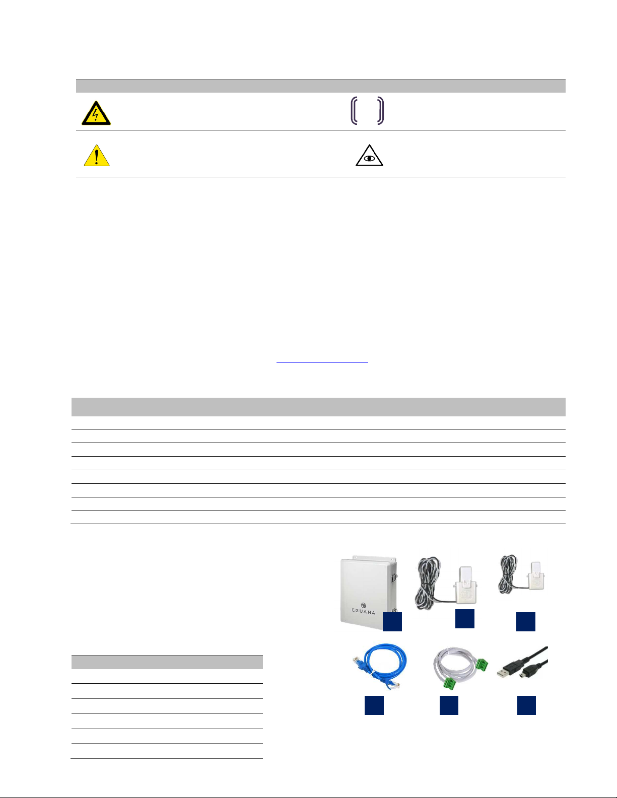
1.3 Initial Inspection of Material List
The system components supplied with your Eguana Evolve™
Hub are shown below. Each component should be inspected
visually for any damage that may have been caused by
shipment. If parts are missing or damaged, please contact
your local distributor.
Term Definition Term Definition
AC / DC Alternating Current / Direct Current NC/NO Normally Closed / Normally Open
AHJ Authority Having Jurisdiction NEC/CEC National (USA) Electric Code / Canadian Electric Code
ARC Auto Recovery Control CS ower Control System (Inverter)
DC Direct Current E (GND) rotective Earth
EMS Energy Management System V hoto-Voltaic
ESS Energy Storage System RF Radio Frequency
GND Ground SOC State Of Charge (Battery)
LED Light Emitting Diode SOH State of Health (Battery)
Item
Description
1 EMS-A Evolve Hub
2 Current transformer – 200 Amp
3 Current transformer – 50 Amp
4 EMS to CS RJ-45 cable
5 AK1 Evolve Hub control cable
6 USB to Mini-USB service cable
(x2)
(x3)
2
3
4
6
5
1
EMS
igure
1
: Evolve Hub materials list.
3
1.4 Special Tools & Hardware
In addition to the standard tools required for enclosure mounting, the following tools should be readily available to complete
the installation.
•Drill and hole saw kit
•RJ-45 crimp tool and RJ-45 connectors
•Wall mounting hardware.
•#0 flat screwdriver.
1.5 Functional Overview
The Evolve Hub is equipped to support an AC coupled solar plus storage installation with backup power to a dedicated
backup electrical panel. The Evolve Hub is a power distribution center for the Evolve ESS, routing all AC power between
the main and backup electrical panels. In the event of a grid outage, the Evolve Hub will be energized by the ESS, which
will island off the main electrical panel. As shown below, the V inverter’s AC output is connected to the backup panel to
support solar charging of the battery during a grid outage.
igure 2: Evolve Hub and Evolve ESS solar plus storage.
1.5.1 Grid Connected Solar plus Storage
The Evolve Hub routes power from the main electrical
panel to the backup panel through the Evolve ESS
Grid/Load transfer circuit when the grid is live and the
battery system is in service (normal operation). The
EMC commands the battery system to charge or
discharge the battery as demanded by the energy
management algorithm. In a self-consumption
algorithm, for example, the EMC calculates the
difference in total load vs. solar V, and routes the
balance of power to/from the battery as needed.
When the battery is full, V power bypasses the
battery to grid/loads. When the battery is at
minimum reserve, all home loads are supplied entirely
by the grid. The following diagram outlines the power
flow possibilities while grid connected.
Note: The Evolve Hub is equipped with an internal automatic bypass switch which provides uninterrupted service to the
backup electrical panel when the Evolve ESS is either not powered (installed but pending permission to operate) or out of
service.
Solar
Inverter
Solar panels
Evolve
Hub
Evolve
ESS
Grid
Load
communication
power
Home
Internet
Service
CT
Main
Electrical
Panel
Backup
Electrical
Panel
Home
loads
Home loads
to grid
Solar
Inverter
Solar panels
Evolve
Hub
Evolve
ESS
Grid
Load
Main
Electrical
Panel
Backup
Electrical
Panel
Home
loads
Home loads
igure
3
: Grid connected solar plus storage.

4
1.5.2 Backup Solar plus Storage
During a grid outage, the Evolve Hub islands the battery system and
backup electrical panel off the grid. In this mode, the EMC is in a
monitoring state, with most control handed over to the Evolve ESS. The
Evolve ESS curtails V when the battery is either full or exceeds the
charge limit of the battery. On low SOC, the battery system goes into a
standby state until either the solar resource or the grid returns.
IMPORTANT! Shutting off the Evolve Hub circuit breaker at the main
electrical panel will place the ESS into backup mode and continue to
energize the backup panel.
1.5.3 Backup Solar PV curtailment method: requency Shift Power Control ( SPC)
During backup power operation of the Evolve ESS, V curtailment is achieved by shifting the frequency up or down to trip
the V inverter. This curtailment method, defined as frequency shift power control (FS C), is required to prevent solar from
over-charging the battery. By default, the Evolve ESS will ramp up frequency to a V trip range of 62.1 Hz, but this is
adjustable depending on the regulatory frequency trip limits within the jurisdiction.
IMPORTANT! V inverters connected to the backup panel must have frequency trip settings programmed within the
following ranges: V low frequency trip range: 57.0 to 59.3 Hz, V high frequency trip range: 60.5 to 62.0 Hz.
If the V inverter cannot be adjusted within the range specified, the V inverter must not be connected to the backup panel.
Note: The Evolve Hub is not suitable for use in applications where the electric utility prohibits V power export to the grid.
For non-export applications, consult your Eguana dealer for alternate EMS panel solutions.
1.5.4 Circuit and system sizing for 100 / 125 / 150 Amp electrical panels
Line side tapping the main electrical panel is required for ESS installations where the electrical service rating is under 200
Amp. Refer to section 2.3, figure 11.
1.5.5 Circuit and system sizing for 200+ Amp electrical panels
The Evolve Hub may be connected to a 200+ Amp electrical panel using a single 40A breaker. For this configuration, the
total solar V output connected to the backup electrical panel will depend on the curtailment features of the solar V inverter.
If the V inverter is equipped with its own curtailment controls that can limit V output to 5kW or less in backup mode, the
maximum rating of the V inverter connected to the Evolve hub is 7.6 kW AC. For V inverters without internal curtailment
methods, the 5 kW V restriction applies. Regardless of V size, this configuration permits the Evolve Hub’s EMS to limit
continuous combined solar plus storage output to 7.6 kW AC (32 Amp).
1.5.6 Over-sized PV systems
For installations with V systems that are larger
than the Evolve Hub and Evolve ESS can
accommodate, the V inverters must be split up
such that the balance of V is wired directly to the
main electrical panel.
An additional CT must be added to the main
panel connected V inverter.
Solar
Inverter Evolve
Hub
Evolve
ESS
Load
Home loads
Backup
Electrical
Panel
Solar
Inverter
Solar panels
Evolve
Hub
Evolve
ESS
Grid
Load
Main
Electrical
Panel
Backup
Electrical
Panel
Home
loads
Home loads
Solar
Inverter
Excess
PV
Solar panels
igure
4
: Backup solar plus storage.
igure
5
: Over
-
sized PV
systems connected to main panel.
Solar panels
5
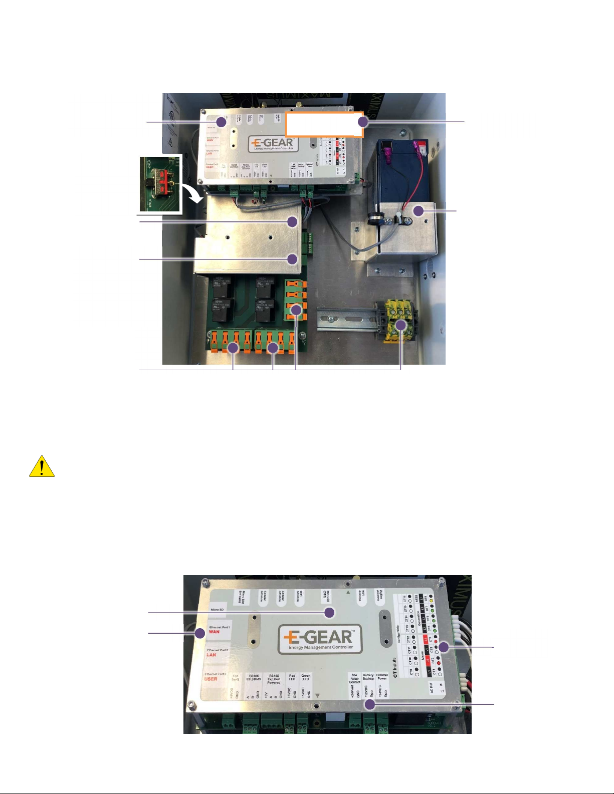
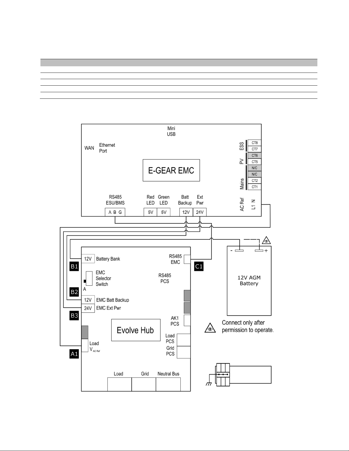
1.6 Internal Component Overview
The Evolve Hub is equipped the following components as identified in the diagram below:
igure 6: Evolve Hub internal component overview.
1.6.1: Energy management controller (EMC)
IMPORTANT! The device unique identifier (UID) & serial number (S/N) tag attached to the front of the EMC is required to
register the device to the cloud so that it may be monitored via the Fleet Installer monitoring system. Record this information
for online registration.
The EMC performs the following functions:
•Commands the battery system to charge and discharge as defined by the selected control algorithm.
•Monitors the home loads, solar V, and battery power via on-board 8 channel power meter.
•rovides the Internet gateway to customer supplied internet router via wired Ethernet, wi-fi, or cellular.
A 12V AGM U S backup battery supplies uninterrupted power to the EMC.
igure 7: EMC feature overview.
E
-
Gear E
nergy
Management
Controller (EMC)
12V AGM Battery
(EMC U S)
AC field
wiring
circuits
Evolve CS
com port
AK1 Evolve
Hub
Control signal
EMS selector
EMC
-
A
UID & S/N Tag
Device unique
identifier tag
Web config tool
Service port
(mini-USB)
channel
power meter
12V AGM
Backup battery
Ethernet to
Internet router

6
2 Installation Planning
Before installing the Evolve Hub, read all instructions and warnings in this manual. The Evolve Hub can be installed in an
indoor and outdoor non-corrosive environment (not marine environment). Wall mounting hardware is not included.
CAUTION! All electrical installation work should be performed in accordance with local building and electrical codes.
WARNING! Isolate the Evolve Hub from all energy sources prior to electrical installation by means of disconnects, breakers or connectors. Failure to
properly isolate either AC or DC sources may result in serious injury or death.
NOTE: Communication cables between the Evolve Hub and the battery system are limited in length. The Evolve Hub
should be installed within 2 ft of the battery system.
CAUTION! Do not install in direct sunlight.
2.1 Installation clearances between the Evolve Hub and the battery system
The Evolve Hub includes a 10 foot communication cable that connects the hub to the battery system. If the installation is
constrained such that the Evolve Hub must be located greater than 24” from the battery system, consult the Evolve ESS or
Evolve LF installation manual for instructions on creating an extended communication cable.
(max dimension with
supplied EMS
communication cable.)
igure
8
: Installation clearances between the Evolve Hub and the Evolve
battery system (base model Evolve ESS shown).

7
2.2 Installation conduit plan – power and communication circuits
The following example outlines the conduit plan for power and communication circuits for a complete solar plus storage
system using the Evolve Hub and the Evolve ESS. (String V inverter shown – replace with equivalent AC combined micro-
inverter output, where applicable).
Table 1: Circuit summary for a solar plus storage installation.
Evolve Hub 40 Amp
Conduit
Ref Circuit Definition
Conductor
(recommended) Circuit rotection
1 ESS grid power 8/3 40 Amp
2 ESS backup power 8/3 40 Amp
3 Main panel power 8/3 40 Amp
4 Backup panel 8/3
40 Amp feeder if total backup ccts exceed 40 Amp/240V
rating
5 Solar V power 8/3 40 Amp
S1
EMS communication
cable
3 meter patch cable included
CAT 5/6 ST -
S2 (x2) CT , 50 Amp 8 ft pigtail 18/2, 300V
-1
-
S3
AK1 Hub Control
Signal cable
harness included , 10 ft 18/2, 300V -
S4 (x2) CT, 200 Amp 8ft pigtail 18/2, 300V
-1
-
S5 CT , 50 Amp 8 ft pigtail 18/2, 300V
-1
-
Note 1: Conductor type referenced where Hub is installed greater than 24” from the Evolve ESS. Signal wiring routed in
conduit with power must be 300V rated. For runs longer than 10 meters, signal separation from power is recommended to
minimize signal interference.
Disclaimer:
Manufacturer supplied components represented here are limited to the CS/Battery, Evolve Hub, and CTs for V, battery, and mains. All
other materials and components represented are customer supplied. CEC/NEC electrical code compliance is the responsibility of the
designer and/or electrical permit holder. Source circuit disconnects for V and Evolve grid/load ports not shown.
igure
9
: Installation conduit plan for a solar plus storage installation
(Evolve L P base model shown).
.

8
2.3 SLD - AC Coupled V System with Back-up ower Operation
The single line diagram shown below is a representation of a typical installation configured for utility interactive and back-
up power operation, with AC coupled V connected to a backup panel. This drawing is a guideline only and is not a
substitute for a code compliant installation. All components required for a code compliant installation are the responsibility
of the licensed installer, including any additional circuit protection requirements not shown here.
NOTES
1 - The backup power bus must be electrically isolated from the main electrical bus. Do not tap
the neutral wires of the main and backup buses. Refer to the installation manual for wiring details.
Load circuits are shown for demonstration. Maximum number of circuits determined by sub-panel
rating. Loads connected to circuits must not exceed nominal power ratings (continuous/surge) of
the inverter.
2 – The battery system must be earth bonded to the building ground to meet lightning protection
requirements.
3 – The battery system load and grid ports are independently controlled circuits. Should the
electrical code require additional “line-of-sight” or dedicated disconnects, a separate disconnect
must be used for each of the grid and load ports. The disconnects and/or circuit breakers must
operate independently of each other, and rated for the branch circuit.
4 - CTs are equipped with 8 ft pigtails. Twisted pair extensions can be run up to 30 ft. CT
extensions should not be required if Evolve Hub is within 4 ft of Evolve system.
5 – Ethernet connection between router and EMC is optional. EMC can communicate using Wi-fi
or cellular.
6 – V cannot exceed 5kW AC output in backup mode. V systems larger than 5kW AC must
have a self-curtailment mechanism (software or hardware) to ensure limit is within the 5kW AC
rating. If curtailment means are not available, the balance of V (if applicable) must be routed
directly to the main panel.
7. For electrical services rated less than 200A, the ESS system must be line side tapped as
shown in figure 11.
Disclaimer:
Manufacturer supplied components represented here are limited to the CS/Battery, Evolve Hub, and CTs for V, battery, and mains. All
other materials and components represented are customer supplied. CEC/NEC electrical code compliance is the responsibility of the
designer and/or electrical permit holder.
igure
10
: Sample single line diagram of an AC coupled solar plus storage installation (Evolve L P shown).
to
Evolve
Hub
igure
11
: Main panel line side tap to
Evolve Hub.

9
3 Installation Instructions
1. Mount the Evolve Hub on the wall
using the 4 mounting screw holes on
the top and bottom flanges. (Mounting
hardware not included).
2. Using the conduit plan in section 2.2,
drill the knockout holes required for
the conduit runs on the bottom face of
the enclosure. Constrain the drill area
as shown.
3. Route all conduit as cabling as
required.
CAUTION! All knockout holes must be sealed to maintain the Type 3R environmental rating of the enclosure after the
installation is complete.
CAUTION! The restricted knockout area is near the Evolve Hub circuitry, so extra care must be taken to avoid internal
components when the knockout holes are being drilled.
CAUTION! Ensure that the Evolve Hub enclosure door is properly seated such that the gasket becomes compressed when
the door is securely closed.
4 Electrical Wiring Instructions
IM ORTANT! Wiring methods must be in accordance with local electrical codes. The installer is responsible for ensuring that
over-current protection is installed and sized appropriately for the AC circuits, in accordance with the National Electrical Code,
ANSI/NF A 70, Canadian Electrical Code and local codes
The patch cables provided in section 4.1 and 4.2 below have pre-assembled connectors at both ends. It is strongly
recommended that these cables are pulled in conduit prior to the power cables.
CAUTION! Do not install cables if any wires appear damaged or
are not terminated improperly. Contact your Eguana distributor for
support.
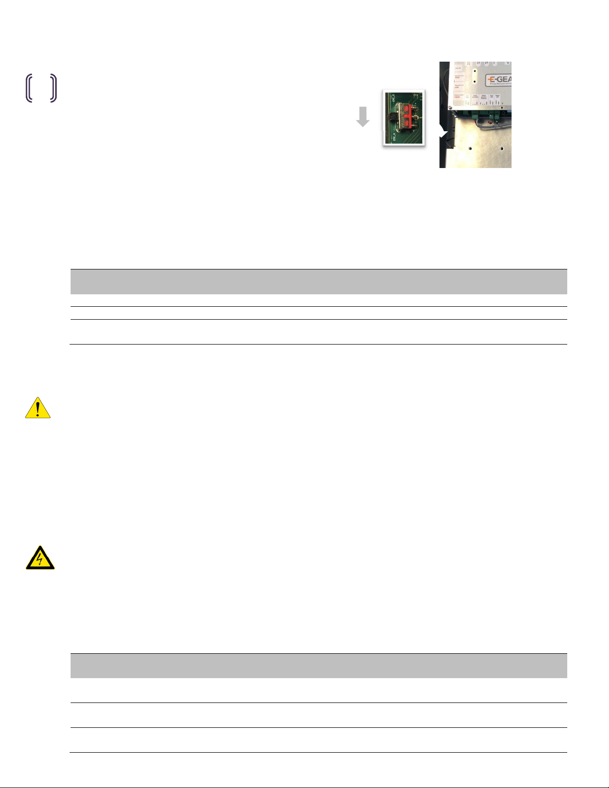
4.1 EMC Cable Connection
1. Terminate the EMC CAT 5 patch cable in the RJ-45 port
as shown.
Note: If a longer extension is required, shielded CAT 5/6 cable
must be used.
4.2 AK1 Cable Connection
1. lug in the AK1 Evolve Hub control cable connector into
the terminal block.
Note: If an AC source disconnect was installed between the Evolve
Hub’s grid port and the Evolve ESS as described in section 2.4 of
this manual, leave the AK1 terminal block unplugged until the
system has permission to operate.
Knockout area:
5” W x 4” H
1.0
”
1.0
”
Restricted knockout area:
7” W x 4” H
1.0
1.0
”
igure
12
: Recommended knock
-
out area.
igure
14
: AK1 cable connection.
igure
13
: EMC cable connection to RJ
-
45 port.

10
4.3 AC ower Connections
All AC power connections to L1, L2, and Neutral are terminated with a hinged pressure clamp connector. Observe the
connector termination instructions for the clamp connector as shown in figure 15. Recommended strip length is 18 mm
(11/16”).
IM ORTANT! Do not terminate fine stranded cable in the connector without the use of ferrules.
IM ORTANT! Do not operate this product if the hinge clamp does not close completely as shown. Improper terminations can
result in fire and/or permanent damage.
CAUTION! To reduce the risk of fire, connect only to a dedicated circuit rovided with a ro riate branch circuit over-
current rotection in accordance with local electrical codes.
WARNING! Im ro er connection of the wiring anel may result in equi ment damage and cause ersonal injury.
Disconnect all AC and DC Sources prior to installation.
CAUTION! The AC grid and load orts are inde endent circuits, controlled internally by an automatic by ass and
transfer switch. Each ort must be connected to electrically isolated anels. Tapping line or neutral wires from the main
electrical panel to the backup panel will result in permanent damage to the product.
4.3.1 Phase Orientation in Split Phase 120/240 Systems
The EMC derives power measurement at the main service, the solar
V inverter AC output, and the ESS. Consistent phase voltage
orientation through the entire installation is critical to proper control
of the system. The initial selection of the phase voltage defined as L1
is established by the placement of the CT referenced as CT1 on the
main feeder to the panel. To ensure the phase wiring to the Evolve
hub maintains consistent polarity, measure the AC voltage between
L1 of the main feeder and the Grid terminals of the Evolve Hub. The
pole that measures 0.0 VAC is defined herein as L1 for the AC wiring
instructions that follow.
Main panel
L1
Evolve Hub circuit
L1
L1 L2
L1 L2
N
To backup panel
To main panel
PCS load port
GND
L2
L1
L2
L1
PCS grid port
Neutral
bus
(common)
Evolve PCS Ports
N
Neutral bus (common)
GND
PCS
igure
15
: AC power wiring.
igure
16
:
Defining L1 with CT1 in the main panel.

11
4.3.2 Main Electrical Panel Connection
Route “AC Grid” L1, L2, Neutral, and Ground to a
dedicated 2-pole backfeed rated breaker in the main
electrical panel.
4.3.3 Backup Panel Connection
Route “AC Load” L1, L2, Neutral, and Ground to a
dedicated 2-pole backfeed rated breaker in the backup
electrical panel.
4.3.4 Evolve battery system: PCS Grid Port Connection
Route “AC_Grid_ CS” L1, L2, Neutral, and Ground
to the CS Grid port inside the Evolve ESS / LF .
4.3.5 Evolve battery sytem: PCS Load Port Connection
Route “AC_Load_ CS” L1, L2, and Neutral to the CS
Load port inside the Evolve ESS / LF .
L1 L2
N
To main panel
GND
L1 L2
N
To backup panel
GND
PCS
L2
L1
N
GND
PCS
L2
L1
N
igure
19
: Evolve Hub to PCS grid port connection.
igure
20
: Evolve Hub to PCS backup port connection.
igure
17
: Main panel connection.
igure
18
: Backup panel connection.
12
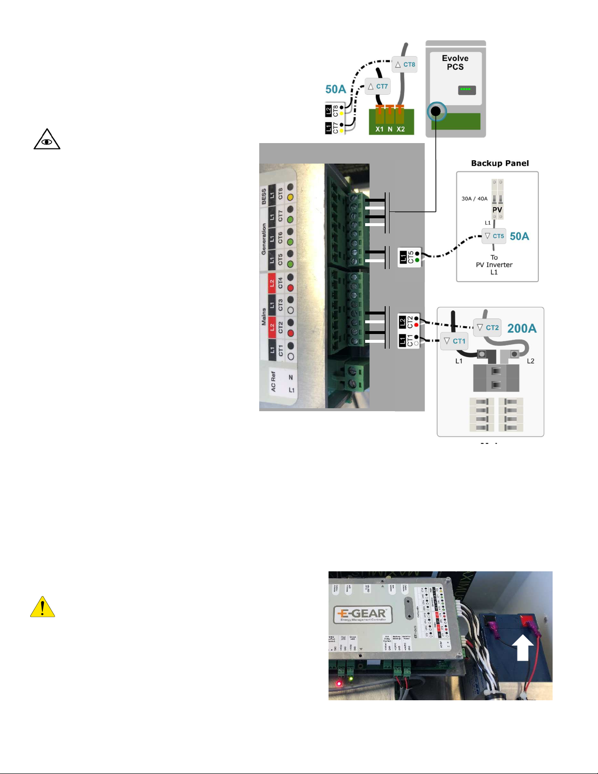
4.4 CT Connections
IM ORTANT! The energy management
system relies on the correct CT orientation
for each of the measured loads, V, and
ESS. Follow these instructions with care.
Note: the positive signal wire is white and
the negative signal wire is black for all CT
models.
4.4.1 Main Electrical Panel CT
Connections
CT direction faces into the home loads
(away from the utility meter). Current
measurement is positive when load exceeds
generation.
1. Terminate CT1 at the L1 feeder of
the main electrical panel.
2. Terminate CT2 at the L2 feeder of
the main electrical panel.
4.4.2 Solar PV CT Connection
CT direction faces into the solar V inverter.
Current measurement is negative when V
is generating.
1. Terminate CT5 at the L1 input of
the solar circuit within the backup
electrical panel.
4.4.3 Evolve PCS CT
Connections
CT direction faces into the Evolve ESS / LF
Current measurement is positive when battery is charging and negative when discharging.
1. Terminate CT7 at the X1 power wire of the Evolve CS.
2. Terminate CT8 at the X2 power wire of the Evolve CS.
4.5 12V Backup Battery Connection
IMPORTANT! Do not complete this connection until the
customer receives permission to operate the system, and the
main panel Evolve Hub breaker is ON. The EMC will be
powered when the 12V battery is connected. Failure to comply
with this instruction may cause irreversible damage to the
battery due to battery drainage without a charge source.
1. Terminate the positive wire on the AGM battery.
igure
21
: CT connections for main, PV, and PCS circuits.
igure
22
: Connecting the AGM battery after permi
ssion
to operate.
13
5 Operation
The EMC inside the Evolve hub is commissioned using a web
browser. Refer to the EMC Administration and Commissioning
Guide for complete instructions on setup for the Evolve battery
sytem. The operation instructions within this manual are limited
to the power up and commissioning test sequence of the Evolve
Hub only.
5.1 EMC selector switch: EMS A
Ensure that the EMS selector switch is in position EMS-A.
5.2 re-startup checklist
The following is a recommended quality inspection checklist prior to power up of the system.
Status
(√ )
Inspection
Reference
AC power terminal clamps closed.
F
igure 15
EM
S
selector switch set to position A.
Figure 23
Ground continuity test
–
inspect and test ground continuity between the Evolve Hub
and Evolve ESS / LF .
5.3 Startup
IMPORTANT! The Evolve Hub must be commissioned as part of the Evolve ESS / LF . The startup procedure provided below
presumes that the CS contained within the Evolve ESS / LF is powered from the battery (DC source), and that the CS is
currently displaying a valid SOC range and is operating in sleep/standby mode. Refer to the startup sequence of the Evolve
ESS / LF Installation and Startup Guide for instructions on startup (turning on DC source only). If AC disconnects or the
optional breaker kit has been installed between the CS grid / load ports and the battery system, leave them in the OFF
position until the power up of the hub has been completed.
1. Turn ON the Evolve Hub breaker in the main panel.
owering up the Evolve Hub will supply power to the on-board EMC. The red and green lights on the bottom of the EMC will
flash for approximately 30 seconds, indicating initialization of the EMC. Following initialization, the lights will remain solid.
CAUTION! Following initial power up of the Evolve ESS / LF , shutting OFF the Evolve Hub breaker at the main electrical
panel will automatically engage the ESS backup power source. The Hub will remain energized at the PCS Load and Load
ports while the ESS is in backup mode.
5.4 ost-startup checklist
The following is a recommended quality inspection checklist following power up of the system.
Status
(√ )
Inspection
Reference
EMC power up status: Green/Red LEDs flashing up to 30 seconds, then solid Green and
Red.
Figure 22
Measure AC voltage at the
AC_G
rid
_ CS
port. (L1
-
N, L2
-
N) (live side of optional breaker
kit, if applicable)
Figure 19
Measure AC voltage at the
AC_L
oad
_ CS
port. (L1
-
N, L2
-
N) (live side of optional breaker
kit, if applicable)
Figure 20
EMS
EMS
-
A
igure
23
: EMS selector switch in position EMS
-
A.

14
Measure AC voltage at the load (backup panel connection) port. (L1
-
N, L2
-
N)
Figure 18
T
est
the
Evolve
Hub
automatic bypass switch
:
(start with AK1 relay connected).
1. Switch Evolve Hub breaker at the main panel to the off position.
2. Switch the feeder breaker of the backup panel to the off position.
3. Wait 4 seconds for the Evolve ESS / LF to transition the CS into Offgrid mode.
4. Measure voltages (L1-N, L2-N) at the Load terminals of the Evolve Hub
(~120VAC).
5. ull the AK1 terminal (will switch the automatic bypass switch off)
6. Measure the voltages (L1-N, L2-N) at the Load terminals of the Evolve Hub (0
VAC).
7. Reconnect the AK1 terminal (after permission to operate (see sec. 5.5)
Figure 14
Figure 18
Figure 14
Figure 18
Figure 14
5.5 ermission to operate checklist
The following is a recommended quality inspection checklist following approval by AHJ inspector to operate the energy
storage system.
Status
(√ )
Inspection
Reference
12V battery positive lead connection to the lead acid battery completed.
Figure 22
AK1 relay connection completed.
Figure 14
6 Maintenance
The Evolve Hub is a maintenance free product. Annual inspection is recommended to ensure the enclosure maintains
mechanical integrity (mounting and environmental protection) and the ventilators are free from obstruction. For heavy soiling
use a soft, dry brush to clean. Do not use any solvents, scouring, or corrosive materials to clean the unit. Never remove or
unplug connections or plugs during cleaning.
7 Troubleshooting
The following is a troubleshooting guide for the Evolve Hub. Refer to the Evolve ESS / LF Installation and Startup manual
for troubleshooting the battery system.
Mode
Condition
Check
Grid connected
No power to
Evolve
Hub and
backup panel. Check Evolve Hub breaker circuit at the main panel.
Grid connected
No V power output
Check V breaker in the backup panel.
Commissioning / Grid
connected
Battery does not charge
when V is operating
1.
Check CT configuration. V measurement is negative when
operating.
2. Check battery SOC (battery does not charge when full).
3. EMS operating in solar self-consumption mode, and home loads are
greater than V.
Grid connected & Backup
Monitoring system not
displaying information in
web portal.
Check internet connection. Check power (Green LED) on EMC panel.
Backup (grid outage) No power to backup loads
Check status of the Evolve
ESS
/ LF
on the front of the CS panel.
Refer
to the Evolve 0513U Installation & Startup Guide for more details.

15
8 Technical Data
8.1 Electrical specifications
Note: About these ratings - The Evolve Hub is a peripheral component of the Evolve ESS / LF . It is a power distribution center with an on-
board energy management system. As such, this product is defined under the category of Interconnection System Equipment (ISE) for use
in utility interactive and/or stand-alone power systems under the scope of the UL1741 Standard, and is intended to be operated in parallel
with an electric power system (E S) to supply power to common loads. The Evolve Hub as a standalone device does not provide grid-
interactive functionality. Where necessary, the ratings included below are listed both as a standalone product, as well as in conjunction with
the Standard for Interconnecting Distributed Resources With Electric ower Systems, IEEE 1547, and the Standard for Conformance Test
rocedures for Equipment Interconnecting Distributed Resources with Electric ower Systems, IEEE 1547.1.
AC ratings – Power distrubution circuits
Nominal Grid voltage
240V/120V split phase
Nominal Grid frequency
60 Hz
Maximum continuous operating current (or Rated
current), AC
40.0
Amps
Maximum continuous operating power (or Rated
power), VA
9600 VA
Maximum AC fault current and duration (short circuit)
14.0 Apk, 2.5 Arms (duration 63.5 ms)
AC connections, number
-
type
4
–
Grid, Load, CS Grid, CS Load
AC voltage operating
range
Max: 100
to 264 Vac
.
Note: UL 1741SA compliant operating limits are
determined by the Evolve ACB05U-L configuration settings
AC frequency operating range
Max:
47 to 63 Hz
.
Note:
UL1741
SA
compliant operating limits are determined
by the ACB05U-L configuration settings
Maximum output overcurrent rating, grid & backup
connection
40
.0
Amps
rotective Class (I, II, or III) Class I
Over-Voltage Category (OVC I, II, III, or IV) OVC III
ollution Degree 3
Lightning protection
IEEE 62.41.2, location
category B, low exposure
General data
Width
x height x depth
15.3” x 17.3” x 6.7”
(389 x 440 x 170 mm)
Weight
23 lbs (10.5 kg)
rotection type
Type 3R
Ambient temperature, relative humidity, altitude
-
20
°
C to +50
°
C, 95%, 2000 m
Cooling method
C
onvection
Installation type
Wall
-
mount (upright)
Enclosure material
Halogen free, self extinguishing fiberglass reinforced polyester
For use only with Eguana Evolve
ES
S
& LF energy storage systems
8.2 Wire and torque ratings
Use solid copper only, 90 °C or higher rating
PCS (AC)
# conductors
AWG
(min to max)
Torque
AC grid, load 3 conductor + E 10 AWG to 6 AWG ush-lock, spring cage
AC PCS grid, PCS load 3 conductor + E 10 AWG to 6 AWG ush-lock, spring cage
Ground Lug 1 conductor 10 AWG to 6 AWG 15.9 in-lbs
Optional breakers 2 pole 10 AWG to 6 AWG 17.7 in-lbs
16
Appendix A: Electrical Block Diagram of Internal Components
The following reference diagram outlines the internal wiring of the Evolve Hub EMS-A model.
Reference
P/N
Title
Notes
A1
801003652
Voltage Sense Cable
120VAC L1 to N power meter reference
B1
801003644
Backup
Battery
Cable
12V AGM battery power
B2
801003650
EMS
-
A 12V
-
24V ower Cable
12V
U S power for EMC
B3
801003650
EMS
-
A 12V
-
24V ower Cable
24V
ower supply for EMC
C1
801003658
Comm Cable
EMC to CS internal communication patch cable
igure 24: Electrical block diagram – internal components.

17
Appendix B: Multi-mode transfer / bypass relay operation
The Evolve Hub and Evolve CS within the Evolve line of energy storage systems provides fully automated multi-mode
operation, including utility interactive and backup (off-grid) operating modes. The diagram below highlights the three main
relay controls used to transfer the backup panel supply source and island the Evolve CS to a micro-grid during a grid
outage. The battery portion of the Evolve ESS / LF is not shown.
Note: while the EMS is responsible for monitoring CS states and controlling the battery discharge / charge rates, the CS
is responsible for the relay controls, and thus does not rely on EMS communication for transfer of the backup panel source.
igure 25: Evolve Hub and Evolve PCS relay protection definitions in an AC coupled solar plus storage installations.
There are three main protection relays within the complete system, defined below, all of which have internal fail-safe fault
verification circuitry to prevent an unsynchronized CS load to grid output connection.
Kx: Evolve Hub bypass / transfer relay
The Evolve Hub bypass / transfer relay ensures the backup panel is connected to the main panel with or without an
operating Evolve ESS / LF system. When standalone, the Kx relay bypasses the energy storage system to power the
backup panel from the main supply. It remains in the NC or bypass state until powered up with the Evolve ESS / LF
initialized and ready for control. Once the energy storage system’s CS is in a “ready” mode, the CS will take over control
of the backup supply source by transferring Kx to NO, and closing K3 for an uninterrupted transfer. Kx will revert to an NC
state with or without a valid grid if the CS reports a critical service state which prevents it from safely operating the K3
transfer relay.
Fail-safe: Critical failure of the Kx relay will prevent CS operation and will result in loss of power to the backup panel.
K3: PCS transfer relay
This relay operates with Kx as defined above when the Evolve ESS / LF is in a “ready” state. See the table below for a
complete list of CS states. This relay opens upon a grid outage to island the backup panel from the main panel. This relay
acts as the CS grid timing / synchronization grid connect relay when the grid supply returns from an outage, allowing
seamless connection of the battery system and the backup panel circuits to the grid.
Fail-safe: Critical failure of the K3 relay will prevent operation of the CS, but will allow the backup panel to be supplied by
the main panel via the Evolve Hub.

18
K1: PCS islanding relay
This relay operates as the IEEE1547 islanding relay for grid interactive disturbances (self-clearing), as well as internal and/or
system faults (critical, service mode: non-clearing).
Fail-safe: Critical failure of the K1 relay will prevent operation of the CS, but will allow the backup panel to be supplied by
the main panel via the Evolve Hub.
PCS and Hub relay state map
The following table summarizes the CS operating states in both utility interactive and offgrid operating modes. The
corresponding relay states and backup panel supply source are also identified. The “ CS ready” column indicates the CS
states of operation where the CS has control over the relays.
PCS
“ready” PCS State K1
State
K3
State
Kx
State
Backup Panel
Supply Source
Utility Interactive
Initializing (power-up) O O NC Grid
* Sleep/Standby (default state following initialize) O C NO CS
* Active Sleep (EMS commanded) C C NO CS
* Grid connected, no charge/discharge (EMS commanded) C C NO CS
* Charging/Discharging (EMS commanded) C C NO CS
* Fault (self-clearing) O C NO CS
* Service mode (resettable) O C NO CS
Offgrid
* Offgrid voltage control C O NO CS
* Sleep/Standby – Overcurrent O O NO None
* Service mode – Overcurrent O O NO None
Sleep/Standby – No Grid O C NC Grid
Service – No Grid O C NC Grid
CS Unavailable - No grid or battery supply O O NC Grid
O – open, C – closed NO - normally open, NC – normally closed
Backup supply interruption period during grid outage / return to grid
A grid outage results in a four second power interruption to the backup panel. On return of the grid supply, the energy
storage system and V inverters sync and grid connect without interruption to the backup panel.
Table of contents
Other Eguana Inverter manuals


