NFO Drives NFO Sinus Optimal Specification sheet

www.nfodrives.se[email protected]
+4645437029TubbaTorg5SE‐37432Karlshamn,Sweden
Operating and
Installation
Manual
NFO Sinus Optimal

NFODrivesAB2020ManualOptimalver.1.1english2
Contents
1Safety aspects.....................................................................................................................................4
2Technical data.....................................................................................................................................5
3Mechanical installation.......................................................................................................................7
3.1Mounting..................................................................................................................................7
4Electrical installation...........................................................................................................................8
4.1Signal terminal connection....................................................................................................9
4.1.1Wiring.........................................................................................................................9
4.2Signal terminals and their use..............................................................................................9
4.2.1Signalterminalsconfiguration..................................................................................11
4.2.2Analoguecurrentinput.............................................................................................11
4.2.3NegativeLogic...........................................................................................................12
4.2.4SerialchannelRS485.................................................................................................12
4.2.5Connectingpotentiometer.......................................................................................12
4.3Power Terminal connection.................................................................................................13
4.3.1Connectorsandcables..............................................................................................13
4.3.2Powerterminaluse...................................................................................................13
4.3.3Connectingmainssupply..........................................................................................14
4.3.4Connectingmotor.....................................................................................................14
5Parameter settings and operation..................................................................................................15
5.1General notes........................................................................................................................15
5.2Keyboard and display..........................................................................................................15
5.3Indicators and Motor status.................................................................................................17
5.4Operating modes..................................................................................................................17
5.4.1Manualmode............................................................................................................18
5.4.2Automode................................................................................................................18
5.4.3Serialchannel/Fieldbusmode.................................................................................19
5.5Parameter specifications.....................................................................................................20
5.6Autotuning and motor parameters......................................................................................23
5.6.1Autotuning................................................................................................................24
5.6.2Alternativetuningmethods......................................................................................24
5.6.3Motorsinparallel.....................................................................................................25
5.7Setting control parameters..................................................................................................25
5.7.1Controlmode,parameterMode...............................................................................25
5.7.2Accelerationandretardationramp,AccelerationandDeceleration........................25
5.7.3Rundelay,PowerOnDelay.......................................................................................26
5.7.4Motorbrake,DC‐Brake.............................................................................................26
5.7.5Autostart,AutoStart................................................................................................26
5.7.6Stopmode,StopMode.............................................................................................27
5.7.7Energysavefunction,EnergySave...........................................................................27
5.7.8Speedregulator,Kp‐speedandTi‐speed..................................................................27
5.7.9Frequencysleepsetting,FrqSleep...........................................................................28
5.7.10Frequencybypass,Bypass‐frandBypass‐BW...........................................................28
5.8Frequency control without load compensation, Freque mode.......................................29
5.8.1Setpointsourceforfrequency,SetpSource.............................................................29

NFODrivesAB2020ManualOptimalver.1.1english3
5.8.2Fixedfrequencysetpoints,FixFrq1‐FixFrq7.........................................................30
5.8.3Analoguefrequencysetpointrange,MinAinFrqandMaxAinFrq..........................30
5.9RPM regulation with speed estimation, Speed mode.....................................................30
5.9.1Setpointsourceforspeed,SetpSource....................................................................30
5.9.2Fixedspeedsetpoints,FixSpd1‐FixSpd7..............................................................31
5.9.3Analoguespeedsetpointrange,MinAinSpdandMaxAinSpd...............................31
5.10Process regulation, PI regulator.........................................................................................31
5.10.1Setpointsource,processregulation.........................................................................32
5.10.2Fixedprocessregulatorsetpoints,FixReg1‐FixReg7...........................................33
5.10.3Sensor.......................................................................................................................34
5.10.4Regulatorsetting,RegAmp,RegKpandRegTi.......................................................34
5.11Motor safety functions..........................................................................................................34
5.11.1PTCinput...................................................................................................................34
5.11.2Electronicmotoroverloadprotection......................................................................35
5.12Output signals to display.....................................................................................................36
5.12.1Relay1(Faultrelay)..................................................................................................36
5.12.2Relay2(Runindication)............................................................................................36
5.12.3Analogueoutput1(voltageandcurrent).................................................................36
5.12.4Analogueoutput2(voltageandcurrent).................................................................37
5.13Reset to factory settings......................................................................................................37
5.14Alarm and fault procedures.................................................................................................37
5.14.1Faultlog....................................................................................................................38
5.14.2Faultmessages..........................................................................................................38
5.14.3Acknowledgefault....................................................................................................38
6Brake chopper and power surge regulator...................................................................................41
7Getting started...................................................................................................................................42
7.1Running in Manual mode.....................................................................................................42
7.2Running in Auto mode at fixed frequency.........................................................................42
7.3Running from terminal, fixed setpoint................................................................................43
7.4Running with analogue setpoint.........................................................................................43
7.5Process regulation with fixed setpoint...............................................................................43
7.6Process regulation with analogue setpoint.......................................................................44

NFODrivesAB2020ManualOptimalver.1.1english4
Introduction
The frequency inverter described in this operating manual is used for frequency (Hz) or speed (rpm) control of
three-phase ac induction motors. This manual describes how to install and use the inverter.
Read the manual carefully before installing the inverter, to ensure you install it correctly and get the maximum
performance out of it.
The inverter has a patented switch circuitry that ensures the motor receives a sinusoidal voltage at all times, under
all operating conditions. This solves all problems related to conventional PWM based frequency inverters, e.g.
electromagnetic interference, ball bearing damages, high earth current and high switching noise.
A 30mA rated RCD (earth leakage circuit breaker) can be used with this frequency inverter.
The inverter also uses the patent "Natural field orientation" which is a vector control method to give perfect speed
control of induction motors all the way from zero to full speed.
1 Safety aspects
Always disconnect the inverter from the mains supply before working on any electrical- or mechanical installation
components.
Installation, maintenance and repairs must always be conducted by staff adequately trained and experienced for
the purpose.
Modifying or replacing any components of the inverter or its accessories will render the inverter warranty null and
void. Should the need for any modifications or replacements arise, always contact NFO Drives AB.
Components in the power section and some components in the signal section are connected to the mains supply
when the inverter is powered.
WARNING! Touching any components with the mains supply connected can be fatal! Always
disconnect the mains supply before opening the cover.
WARNING! Even when disconnected from the mains supply, the inverter may still contain lethal voltages
due to its buffer capacitors. Always wait at least five minutes to make sure no voltage remains before
working on the inverter.
WARNING! The heat sink of the inverter may get hot, depending on operating conditions. Do not touch.
For connection of mains supply, the inverter shall be permanently connected to fixed wiring including a circuit
breaker which must be used to ensure all-pole disconnection under overvoltage III conditions.
The inverter shall always be connected to protective earth (P.E.) when the mains supply is connected.
If the motor temperature sensor (PTC/Klixon) functionality is used, the sensor and its wiring must supply
adequate isolation and comply with installation requirements for the equipment in use.
The level of integrity offered by the drive control input functions – for example stop/start, forward/reverse and
maximum speed, are not sufficient for use in safety-critical applications without independent channels of
protection. All applications where malfunction could cause injury or loss of life must be subject to a risk
assessment and further protection provided where needed.

NFODrivesAB2020ManualOptimalver.1.1english5
2 Technical data
Table 1. Inverter ratings for 380-480V 3~ 50/60 Hz Type TN electrical supply network
Art. no.
Rated
output
power
Rated
output
current
[1]
Max
output
current
[2]
Apparent
output
power
[3]
Absolute
losses
[4]
P
L,CDM(90,100)
Efficiency
class
[5],[6]
Standby
power
[7]
Size [mm] Weight
[kg]
NFO
3A4D3490D 2.2 kW 1.0-4.9 A 5.8 A 3.3 kVA 0.14 kW IE2 7.5 W 390x190x160 7.0
Notes:
[1] The inverter is optimized for use at a wide range of nominal motor currents in the range of 0.37 kW to 2.2 kW.
[2]
The inverter application should not be dimensioned for higher continuous current than Rated output current.
However, it can supply Max output current for infinite time, but it may be detrimental to its life span.
[3]
Apparent output power Sr,equ used for IE (International Efficiency) classification.
[4]
Measured at a current displacement factor (cos ) of 0.77.
[5]
CDM (Complete Drive Module) efficiency class according to Commission Regulation (EU) 2019/1781 and
IEC 61800-9-2:2017.
[6]
Due to sinusoidal voltage output from the NFO inverter, the expected additional harmonic losses in the motor,
which are present when using a PWM inverter, are now absent.
IEC 61800-9-2:2017: “When [three-phase induction motors] are operated on a CDM, additional harmonic
losses PLHL = rLHL × PLTsin are caused by the non-sinusoidal voltage supply”. The increase of motor losses as a
result of PWM operation (rLHL) are estimated to 15% of the total losses. According to the reference model for a
2.2kW IE2 or IE3 induction motor, this corresponds to about 0,05 kW.
When determining the overall efficiency of the PDS (Power Drive System, i.e. inverter and motor together), it
should be taken into account that motor losses are approximately 15% lower when using an inverter with
sinusoidal voltage output, than it would be if using a conventional PWM inverter.
[7]
No external control equipment connected to the 24V supply output, and cooling fan regulator at low speed.

NFODrivesAB2020ManualOptimalver.1.1english6
Table 2. Common data
Inverter output
Output volta
g
e wave form Sinusoidal
Output frequenc
y
0
–
150 Hz
Control modes
Frequenc
y
control 0
–
150 Hz, Vector control without slip compensation
Speed control 0
–
9000 rpm, Vector control with slip compensation
Re
g
ulators
Process control PI with extern analo
g
ue feedback in all control modes
Speed re
g
ulator Re
g
ulator for optimal d
y
namic performance
I/O No. Name Confi
g
urable levels
Di
g
ital control inputs 8 DIN1
–
DIN8
Analogue control inputs 2 AIN1, AIN2 0-10V, 2-10V, ±10V,
0-20mA, 4-20mA, ±20m
A
, Pot
Di
g
ital outputs 2 Re1, Re2 Rela
y
, max 50VDC
Analogue outputs 2 AOUT1, AOUT2 0-10V, 2-10V, ±10V,
0-20mA, 4-20mA, ±20m
A
Volta
g
e output 1 +24V max 200m
A
Serial control 2 USB 2.0 T
y
pe B, RS485
Serial protocols 2 Modbus RTU, NFO
Fieldbus options CAN open, Profibus DP, Profinet, Modbus TCP, BACnet [1]
Motor safet
y
Thermistor input PTC or Klixon
Electronic motor overload
protection Switch off if motor is loaded over rated power for a long time
Ambient conditions
A
mbient operatin
g
temp. -10 – +45 C
Stora
g
e temp. -20 – +60 C
Humidit
y
0
–
90%, non-condensin
g
Protection class IP55 accordin
g
to SS-EN 60529
EMC certification
Emissions: EN 55011:2016 EN, 55011/A1:2017, EN 61000-3-3:2013
Immunity: EN 61000-6-2:2005, EN 61000-4-2, -3, -4, -5, -6, -11
For use without shielded cables or additional EMC filter.
Electrical safety
Low Voltage Directive EN 61800-5-1:2007, EN 61800-5-1/A1:2017
Motor terminal short circuit protection [2] according to IEC 60364-4-41:2005 /
AMD1, clause 411. The short circuit protection functionality operates
regardless of motor cable area, cable length, or other cable properties, and
re
g
ardless of mains power suppl
y
impedance.
Climatic tests Dry heat test IEC 60068-2-2
Damp heat test IEC 60068-2-78
Vibration test IEC 60068-2-6
Notes:
[1] Limited availability for all fieldbus options.
[2] If short circuit should occur, the inverter may get damaged. However, it will prevent damage of connected
equipment, fire and other hazards.

NFODrivesAB2020ManualOptimalver.1.1english7
3 Mechanical installation
When unpacking the inverter, carefully inspect the product and make sure it has not been damaged during
transportation. Inverter with cracks, dents or other visual damage shall not be installed.
The inverter must not be installed such that outlet air from another inverter or other equipment blows directly
into the inverter air intake. A minimum of 80 mm clearance must be kept above and below the inverter, and a
minimum of 20 mm vertical gap must be kept between inverters, to ensure sufficient air flow.
All terminals are accessed by opening the plastic cover. To be able to use the snap-and-hold-open
functionality of the cover, a free space of 200 mm is required above the inverter.
During installation, it is important that no foreign object, such as borings or screws, fall into the inverter as a
short circuit may occur.
After installation, make sure all grommets at the cable entries are mounted and the cover is closed and
secured with its screws to avoid touching dangerous voltage.
3.1 Mounting
Unscrew the two lower captive screws and loosen the inverter from the backplate. Fasten backplate to a vertical
surface using four screws. Make sure that the top mounting screws are sufficiently strong to hold the entire weight
of the inverter. Place the inverter on the backplate by mating the chassis cut-out to the backplate hooks. Tighten
the lower captive screws on both sides.
The cover is opened by unscrewing the two captive screws in the plastic cover and fold up the cover until it snaps
tight. There are two possible positions for the cover. Close the cover by pulling it out and fold down. Be careful not
to break the snaps in the cover when folding down. Tighten the screws in the plastic cover.
The plastic cover can be removed by unscrewing the two upper screws after the cover is opened. The cable from
the cover to the control board must be carefully removed from the control board. Replace in reverse order.

NFODrivesAB2020ManualOptimalver.1.1english8
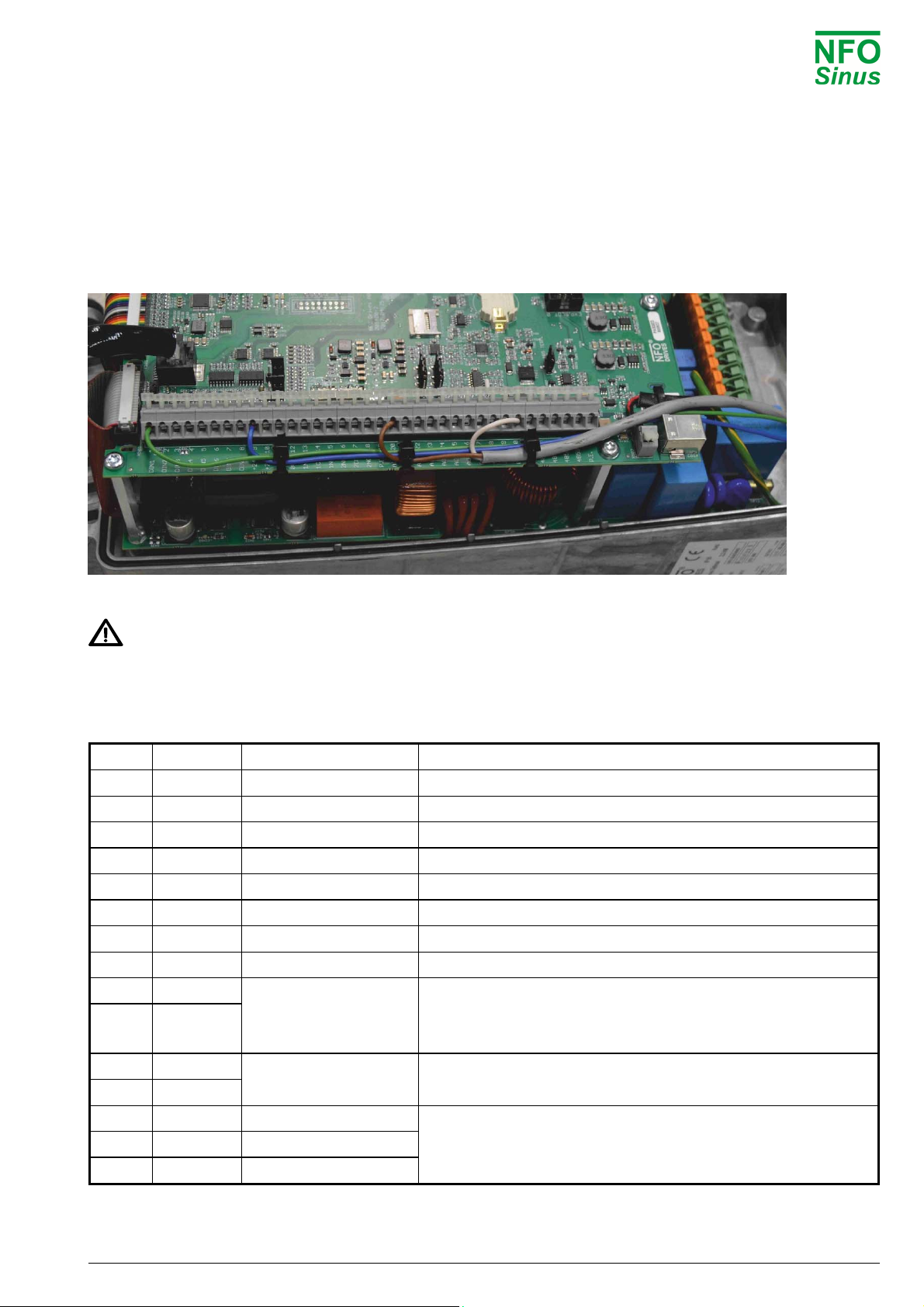
4 Electrical installation
The following schematics shows the inverter default connections and default functions of the I/O:
Fig.1. Default configuration
Terminals 11, 12 30 and 31 (0V) are connected to PE with a 1MΩresistor but can be connected galvanically to PE
via an external jumper to terminal 19 or 36 (PE). These terminals may vary in terms of potential by up to 100 V from
PE. The USB contact is galvanically connected to 0V.
AIN1.N and AIN2.N are connected to 0V by jumpers J701 and J703.
Warning! If option Autostart is ON and there is a run signal to the inverter (DIN1, terminal 1), the inverter will
start the motor when powered up.
An external brake-resistor must be fitted if the retardation time is less than 5 sec, see section 6.
Warning! If the Motor Safety Thermistor is to be used, jumper J802 must be set accordingly, see 5.11.1.
Note! A motor safety switch can be mounted between the inverter (terminals U, V and W) and the motor, but
it must only be operated (switched off or on) when the motor is not running.
NFODrivesAB2020ManualOptimalver.1.1english9
4.1 Signal terminal connection
The signal terminals are of type “tension clamp spring connection” with a usable cable cross-section of 0.13 - 2.5
mm² (AWG 26 - AWG 14). To connect the cable, carefully push the actuator downward. If a tool is used, make sure
it does not damage any components on the circuit board!
4.1.1 Wiring
The signal lines should be fixed to the PCB with at least 2 straps.
Fig. 1. Signal line wiring.
Make sure the signal wires have sufficient isolation when passing power cables.
4.2 Signal terminals and their use
The following control signals with its default configuration are available:
Term. Name Function Default function description
1 DIN1 Di
g
ital input 1 Run si
g
nal Start/stop
2 DIN2 Di
g
ital input 2
3 DIN3 Di
g
ital input 3 Direction of rotation
4 DIN4 Di
g
ital input 4
5 DIN5 Di
g
ital input 5 Select fixed frequenc
y
(
see table 8 pa
g
e 19
)
6 DIN6 Di
g
ital input 6 Select fixed frequenc
y
(
see table 8 pa
g
e 19
)
7 DIN7 Di
g
ital input 7 Select fixed frequenc
y
(
see table 8 pa
g
e 19
)
8 DIN8 Di
g
ital input 8 PTC motor protection
9 +24V
+24V max 200mA regulated voltage to digital inputs or external
transmitters. Short circuit protected. Could also be used for
auxiliar
y
control power suppl
y
.
10 +24V
11 0V 0V, I/O Ground
12 0V
13 RE1.NO Rela
y
1 NO Fault relay, potential-free contact max 1 A, 50 V DC.
If fault present, terminals 14 are 15 closed.
14 RE1.COM Rela
y
1 COM
15 RE1.NC Rela
y
1 NC

NFODrivesAB2020ManualOptimalver.1.1english10
16 RE2.NO Rela
y
2 NO Run indication, potential-free contact max 1 A, 50 V DC.
Terminals 16 and 17 are closed when motor is running.
17 RE2.COM Rela
y
2 COM
18 RE2.NC Rela
y
2 NC
19 PE Protective earth
20
A
IN1.P
A
nalo
g
ue input 1, pos
A
nalo
g
ue setpoint input, positive
21
A
IN1.N
A
nalo
g
ue input 1, ne
g
A
nalo
g
ue setpoint input, ne
g
ative
(
0V, I/O Ground
)
22
A
IN2.P
A
nalo
g
ue input 2, pos Process re
g
ulator actual value input, positive
23
A
IN2.N
A
nalo
g
ue input 2, ne
g
Process re
g
ulator actual value input, ne
g
ative
(
0V, I/O Ground
)
24
A
OUT1.I
A
nalo
g
ue output 1, I Current output 1
25
A
OUT1.U
A
nalo
g
ue output 1, U Volta
g
e output 1, impedance 50Ω
26
A
OUT2.I
A
nalo
g
ue output 2, I Current output 2
27
A
OUT2.U
A
nalo
g
ue output 2, U Volta
g
e output 2, impedance 50Ω
28 +24V +24V (same as terminal 9 and 10)
29 +24V
30 0V 0V, I/O Ground (same as terminal 11 and 12)
31 0V
32 RS485.
A
RS 485,
-
33 RS485.
A
34 RS485.B
RS 485,
+
35 RS485.B
36 PE Protective earth
Table 3. Signal terminals and their use
Digital inputs (terminals 1 - 8), positive logic:
Maximum input voltage: 30V
Switch level: 13V (input voltage higher than switch level is considered as active level)
Impedance: 10kΩ
Digital inputs (terminals 1 - 8), negative logic:
Maximum input voltage: 30V
Switch level: 9V (input voltage lower than switch level is considered as active level)
Impedance: 10kΩ
NFODrivesAB2020ManualOptimalver.1.1english11
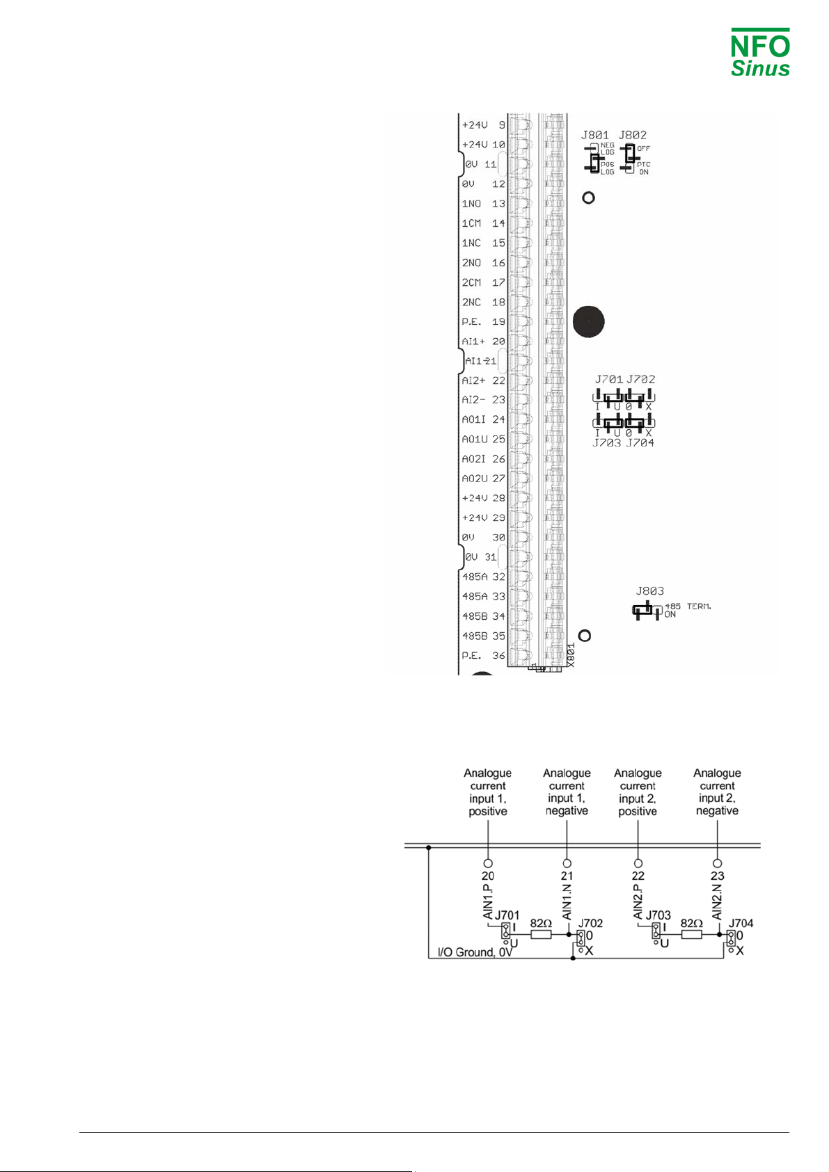
4.2.1 Signal terminals configuration
The jumpers on the control board are for the
configuration of the analogue- & digital-
inputs as well as the serial RS485 channel.
The placement and default settings of the
jumpers are seen in Fig. 2 and explanations
about their use are described in the following
sections.
Fig. 2. Jumper placement and default settings
4.2.2 Analogue current input
To use analogue current input 1, move J701
to “I” position. If more than one unit is
controlled by a single current input signal,
then J702 should be removed or moved to
position “X”. This allows the common-mode
voltage to vary by ±24V from 0V
The same applies for J703 and J704 when
using analogue current input 2.
Input resistance: 82Ω.
Note: When used as voltage inputs, J702 and
J704 must be mounted in “0” position.
Fig.3. Analogue current input configuration

NFODrivesAB2020ManualOptimalver.1.1english12
4.2.3 Negative Logic
The inverter can be configured to run the
digital inputs (DIN1 to DIN8) with negative
logic. This is done by moving jumper J801 to
the “NEG LOG” position. The inputs are then
made active by connecting them to the 0V
(terminals 11,12, 30 or 31), see Fig.4.
If the PTC function is to be used with
negative logic, an external resistor (1,5kΩ,
min 1/2W) must be connected between the
terminals DIN8 and 0V. And J802 must be in
the OFF position.
Fig.4. Connection via negative logic (jumper J801 moved)
4.2.4 Serial channel RS485
The inverter can be controlled via an RS485 type
serial channel. Connection is made through
terminals 32 (RS485.A) and 34 (RS485.B). If the
signals are to be bridged to further units, terminals
33 and 35 can be used as in Fig.5.
Termination of the serial channel with 124Ωresistor
is available by moving jumper J803 to position “485
TERM. ON”.
Fig.5. Connection RS485
4.2.5 Connecting potentiometer
If a potentiometer is to be used as the setpoint
source, it is connected between the analogue
voltage output AOUT2.U (27) and the analogue
voltage input AIN1.P (11 or 12).
Change parameter AinSet to Pot and this
automatically configures AOUT2.U to supply 10V.
The value of the potentiometer should be between
4,7kΩand 22kΩ. A lower value will give a lower
maximum frequency because of a 50Ωoutput
impedance in AOUT2.U.
Fig.6. Connecting potentiometer

NFODrivesAB2020ManualOptimalver.1.1english13
4.3 Power Terminal connection
4.3.1 Connectors and cables
The power terminals are of type “Push-Lock” with a cross section of 0.2 – 6mm2(AWG 24 – AWG 10). Use cable
type(-s) with operating temperature rating of at least 70C. The cable insulation shall be stripped 12 mm before
pushed into the connector, and then the lever shall be closed.
It is important that the lever is pushed to its fully closed position, as shown below:
Fig.7. The connection lever of the power terminals
4.3.2 Power terminal use
Terminal Function Description
L1
L2 Mains supply Mains supply 380–480V 3~
L3
PE Protective earth Power supply protective earth connector
B Brake resistor Connection for external brake resistor (between B and +)
- - Internal DC link voltage negative and positive terminals.
+ + Positive terminal also used for external brake resistor (option)
PE Protective earth Motor protective earth connector
U Motor phase connectors - To be connected to the
V Motor outputs correct poles of the motor. Incorrect connection can
W cause erratic/unwanted behaviour of the motor.
Table 4. Use of power terminals
When installing two or more inverters together, with one or more of their motors running regeneratively, the
inverters DC link terminals (+ and -) can be connected to each other (thus supplying energy to each other).
Note! As there are component tolerances in the inverters, the link voltage may vary slightly between units, so an
equalising resistor and ultra-fast fuse must be fitted to each line.
Contact NFO Drives AB for correct dimensioning.

NFODrivesAB2020ManualOptimalver.1.1english14
4.3.3 Connecting mains supply
Three-phase feed inverters are connected to a three-phase mains network at a nominal voltage of 380
–
480 V
50/60 Hz between terminals L1, L2, L3 and PE. (PE = Protective Earth = ground).
Recommended slow-blow fuses for three-phase supply:
Model 2.2 kW
(
1.0
–
4.9
A
)
Fuse 10
A
Table 5. Recommended fuse
With the mains supply connected correctly and the motor running, the inverter draws less than 2 mA earth current
in the PE connection. An earth leakage circuit-breaker or RCD 30mA can be used with the inverter.
Turning on and off the mains supply too frequently can damage the inrush circuit of the inverter.
Wait at least 1 min between each power up. Do not use the mains supply for frequent on/off control
of the motor.
4.3.4 Connecting motor
Connect motor cables to terminals U, V, W and PE.
Nominal motor voltage for three-phase fed inverters is 400V. A motor with a nominal voltage of 400V–Y / 230V–D
must be configured for Y-connection, and a motor with nominal voltage of 690V–Y / 400V–D must be configured for
D-connection.
Autotuning must always be performed before first motor start, see section 5.6
EMC standards is met without use of shielded motor cables, if the inverter is correctly installed.
There is no limit to the length of the motor cable as the inverter always supplies a sinusoidal voltage
to the motor. Of course, a slight drop in the voltage (resistance in cables) must be allowed for, which
is accounted for during the autotuning. Use cable with a resistance in each phase that is sufficiently
(and significantly) lower than the resistance in each motor phase winding (stator resistance).
NFODrivesAB2020ManualOptimalver.1.1english15
5 Parameter settings and operation
5.1 General notes
The inverter can be used in the following modes of control:
Frequency regulation of an induction motor (motor speed is not compensated for load variations) with a fixed
digital or analogue setpoint, see section 5.7 for more details. The motor's electrical frequency is shown on the
display. This operating mode is called Freque and is the factory-set mode.
Speed regulation for an induction motor with speed calculation (motor speed compensated for load variations)
with a fixed digital or analogue setpoint, see section 5.9 for more details. The motor's estimated speed is
shown in the display. This mode is called Speed.
In the above modes, the setpoint can also be the output from the internal PI-regulator with feedback from a process
controlled by an induction motor.
Autotuning must always be performed before first motor start, see section 5.6
Notes:
[1] Type = Init parameters can only be changed via initialising
in local mode.
Type = Init/Run parameters can be changed in any mode.
Type = Read parameters are read-only.
[2] Other combinations of default values for Acceleration, Deceleration, Kp-speed
and Ti-speed are available.
Autotuning and motor parameters.
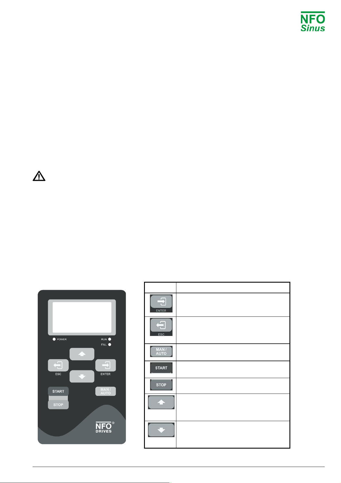
5.2 Keyboard and display
The figure and table below show the keyboard and general key functions.
Button Function
Save parameter.
Enter into parameter or parameter-group.
Leave parameter unsaved.
Leave parameter, parameter-group or
Setup. Enter Setup.
Toggle Operating mode between Manual
and Auto.
Starts motor in Manual mode. Starts motor
in Auto mode if Run signal (DIN1) active.
Stops motor in all modes.
Increase parameter when changing.
Moves between parameter-groups or
parameters.
Decrease parameter when changing.
Moves between parameter-groups or
parameters.

NFODrivesAB2020ManualOptimalver.1.1english16
Fig. 8. Keyboard Table 6. Button functions
After power up, the inverter enters the RUN screen. This screen shows the status of the inverter. Setup is reached
by pressing (Esc). From the Setup Screen, the RUN screen is entered again by pressing (Esc).
When a parameter or a parameter-group is selected, its text is inverted. By pressing (Enter) the parameter or
parameter-group is entered.
Toggling between a parameter or parameter-group and the RUN screen can always be done by pressing and
holding (Esc) for 2s.
The value of a given parameter can be increased or decreased by pressing (Up) or (Down). When
adjusting parameters, the increment increases successively. When any parameter is changed but not yet saved, its
value is highlighted. To save the value, press (Enter).
The following flowchart Fig. 9 shows how different screens are reached, examples of appearance and explanation
of text:
Fig. 9. Programming flowchart and screen examples with explanations
NFODrivesAB2020ManualOptimalver.1.1english17
5.3 Indicators and Motor status
The indicator lights, below the display of the keyboard, mean the following:
POWER Indicates the inverter is live.
RUN Lights up when the motor is running.
FAIL Inverter faulty
The Motor status, shown in the lower left corner of the display, means the following:
Run Motor is running.
Stop Motor standing still.
StBy Inverter standby in Auto mode, waiting for Run signal (DIN1).
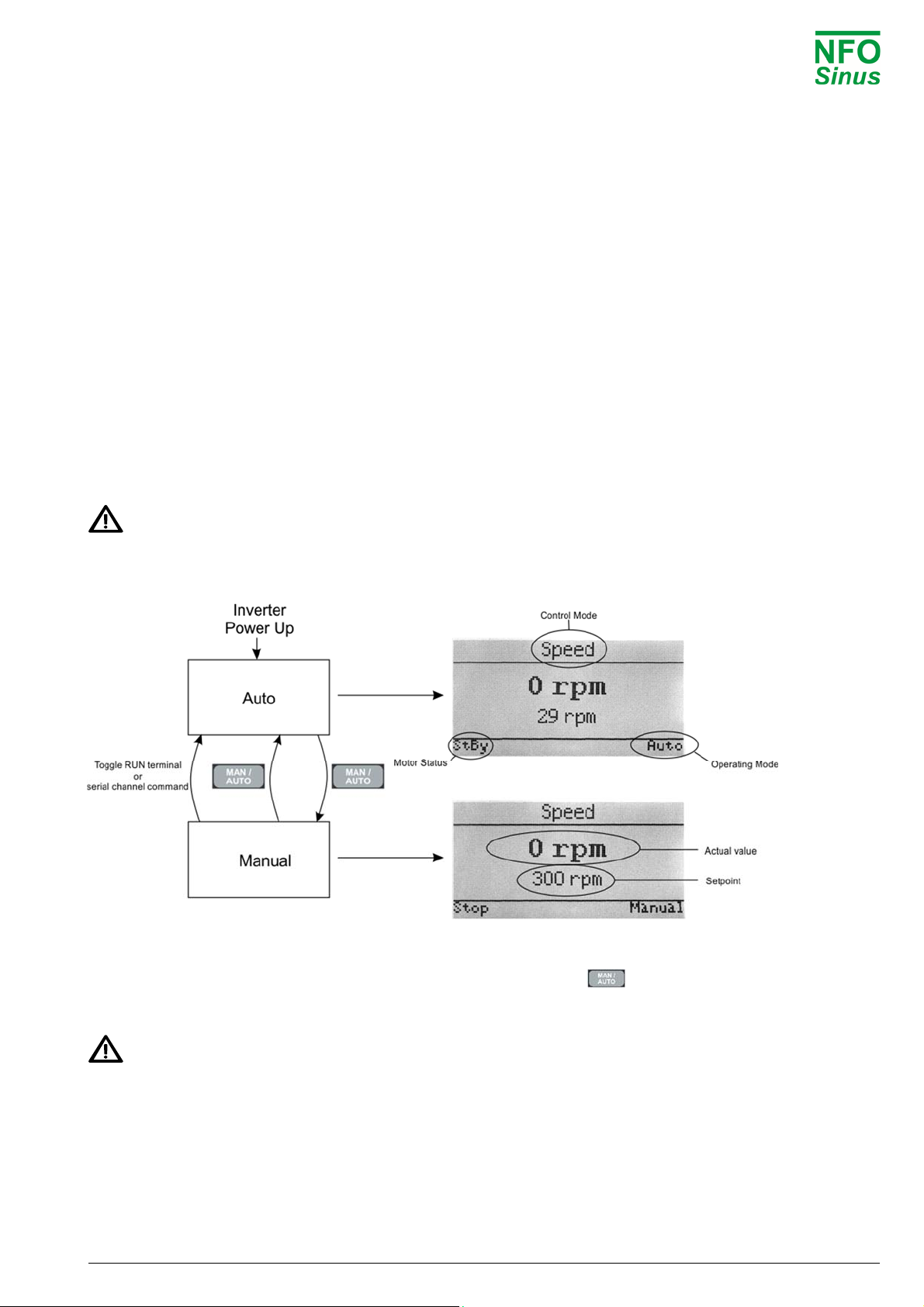
5.4 Operating modes
The inverter has 2 operating modes, Auto and Manual. When starting and initiating the inverter it enters the Auto
mode and the RUN screen is shown. The Auto mode is used for controlling the inverter with an external start
command, either from terminal 1 (DIN1) or with a serial channel command. The Manual mode is normally used for
test and programming, as well as running the inverter, with the use of the keyboard or NFO Sinus Manager SW.
The inverter will start the motor automatically when it is powered up if terminal 1 (DIN1) is active and
parameter AutoStart=ON.
The following flowchart Fig. 10 shows how to switch between Manual and Auto modes:
Fig. 10. Flowchart switching between modes and screen examples
You can toggle between Auto and Manual mode at any time by pressing .
The chosen mode is displayed in the right lower corner of the screen.
The inverter starts automatically, or continues to run if it is running, when entering Auto mode if terminal 1
(DIN1) is active.

NFODrivesAB2020ManualOptimalver.1.1english18
5.4.1 Manual mode
You can switch to Manual mode at any time by pressing . If the motor is running in Auto mode, it will continue
to run in Manual mode with the setpoint the same as the actual value at the time of the switch over.
The setpoint and actual value are shown on the screen.
The setpoint is increased by pressing , decreased by pressing and saved by pressing .
The motor is started by pressing and stopped by pressing . When the motor is running, Run is shown
in the lower left corner of the screen. When the motor is stopped, Stop is shown.
NB! In St-mode, Ramp; run will be shown, after stop has been pressed, until the motor has stopped.
5.4.2 Auto mode
You can switch to Auto mode at any time by pressing . If terminal 1 (DIN1) is active the motor starts. Auto
mode can also be reached by toggling terminal 1 (DIN1) or by serial channel command. If the inverter is in Auto
mode but active run signal terminal 1 (DIN1) is missing, the Motor status shows StBy.
The source for the setpoint is governed by the parameter Setp Source for the control mode concerned as in Table
13 and Table 14.
Selecting Mode: Terminal enables the setpoint source to be selected from the signal terminals as in Table 7. If
using analogue setpoints, the signal type is selected using parameter AinSet from the Control parameter group as
in Table 8. Setpoint sources can be changed while inverter is running.
Analog F: runs clockwise between the lowest setpoint (Min Ain Frq) and the highest setpoint (Max Ain Frq).
Analog R: as Analog F, but running counter-clockwise.
Fix-1 F - 7 F: runs clockwise with setpoint from corresponding fixed value parameter for the selected control mode
Fix-1 R - 7 R: as Fix-1 F – Fix-7 F, but running counter-clockwise.
PI control F or PI control R enables the Pi regulator either clockwise or counter-clockwise according to 5.10.
Fixed value parameters can be changed on the fly, in which case the new setpoints apply immediately.

NFODrivesAB2020ManualOptimalver.1.1english19
Function Run signal Direction of
rotation PI control Fixed
frequency 1 Fixed
frequency 2 Fixed
frequency 3
Terminal
Function DIN1 DIN3 DIN4 DIN5 DIN6 DIN7
Analogue Forward 1 0 0 0
0
0
Analogue Reverse 1 1 0 0 0 0
Fix-1 F 1 0 0 1 0 0
Fix-2 F 1 0 0 0 1 0
Fix-3 F 1 0 0 1 1 0
Fix-4 F 1 0 0 0 0 1
Fix-5 F 1 0 0 1 0 1
Fix-6 F 1 0 0 0 1 1
Fix-7 F 1 0 0 1 1 1
Fix-1 R 1 1 0 1 0 0
Fix-2 R 1 1 0 0 1 0
Fix-3 R 1 1 0 1 1 0
Fix-4 R 1 1 0 0 0 1
Fix-5 R 1 1 0 1 0 1
Fix-6 R 1 1 0 0 1 1
Fix-7 R 1 1 0 1 1 1
PI control F 1 0 1 x x x
PI control R 1 1 1 x x x
Table 7. Digital input settings for digital signal terminals.
Parameter
AinSet setting Analogue value Input (terminal)
0-10 V Voltage 0-10V 20 (J701 at “U” position)
2-10 V Voltage 2-10V 20 (J701 at “U” position)
+/-10 V Voltage +/- 10V 20 (J701 at “U” position)
Pot Potentiometer 11, 20 and 27 (J701 at “U” position)
0-20 mA Current 0-20mA 20 and 21 (J701 at “I” position)
4-20 mA Current 4-20mA 20 and 21 (J701 at “I” position)
+/-20 mA Current +/- 20mA 20 and 21 (J701 at “I” position)
Table 8. Settings for analogue setpoint AIN1 inputs at analogue signal terminals
5.4.3 Serial channel/Field bus mode
There are two different standard communication protocols available, NFO’s own bus (NFO) and Modbus
RTU/ASCII. Both communicate via USB or RS485. As an option there are modules for other fieldbuses available,
please contact NFO Drives AB.
For controlling the inverter or altering its parameters via Modbus or NFO-bus, the Windows program “NFO Sinus
Manager” is available and can be downloaded from web page www.nfodrives.se.

NFODrivesAB2020ManualOptimalver.1.1english20
5.5 Parameter specifications
Parameters are divided into parameter groups, as shown in the table below:
Motor Control Freque Speed PI Reg Output Comm. Status Error GUI
P-Nom Mode Setp Source Setp Source Setp Source Relay1 Mode RS485 U-rms Erro
r
-log Backlight Time
U-Nom Acceleration Fix Frq 1 Fix Spd 1 Fix Reg 1 Relay1 Freq USBPort I-rms Restart Delay User Level
f-Nom Deceleration Fix Frq 2 Fix Spd 2 Fix Reg 2 Relay2 Mode Fieldbus P-out Trip Time Pwd Lvl 3
N-Nom PwrOn Delay Fix Frq 3 Fix Spd 3 Fix Reg 3 Relay2 Freq Auto Reset PF AC Fail Pwd Lvl 2
I-Nom DC-B
r
ake Fix Frq 4 Fix Spd 4 Fix Reg 4 Aout1 Mode DC Link Temp Hi Pwd Lvl 1
cos Ain Set Fix Frq 5 Fix Spd 5 Fix Reg 5 Max Aout1 Inv Status PTC Temp
Tuning Auto Start Fix Frq 6 Fix Spd 6 Fix Reg 6 Aout2 Mode Frq Set Overload
R-stato
r
Stop Mode Fix Frq 7 Fix Spd 7 Fix Reg 7 Max Aout2 Frq Act Ain Fail
R-roto
r
Energy Save Min Ain Frq Min Ain Spd Set Min Spd Set DC Low
L-main Kp-Speed Max Ain Frq Max Ain Spd Set Max Spd Act DC High
Sigma Ti-Speed Act Min Trq Set GND Fail
I-Magn Frq Sleep Act Max Trq Act Short Circuit
I-Limit Bypass Frq Ain Act Reg Set I-Magn Low
Bypass BW Reg Amp Reg Act Cu
r
rent Low
Reg Kp M-temp Cu
r
rent High
Reg Ti Op Time Run Fail
Unit RunTime
Sense Unit B
r
eak Time
Sense Min1
Sense Max1
Sense Min2
Sense Max2
Table 9. Parameter groups and parameters.
Only the parameter groups for the control mode selected are displayed, i.e. either Freque or Speed.
The table below shows all inverter parameters, divided into parameter groups.
This manual suits for next models
1
Table of contents
Other NFO Drives DC Drive manuals

Popular DC Drive manuals by other brands

SHS
SHS EtherCAT HT7 user manual

Minarik
Minarik MMBOSS Series user manual

Danfoss
Danfoss VLT HVAC Drive FC 102 operating guide

Linear Technology
Linear Technology DC1187A quick start guide

Anaheim Automation
Anaheim Automation DPD75601 user guide

Johnson & Johnson
Johnson & Johnson DePuy Synthes Electric Pen Drive Instructions for use


SOMFY
SOMFY MR instructions

Lenze
Lenze POWERLINK E84DGFCL Series Communications manual

TOX PRESSOTECHNIK
TOX PRESSOTECHNIK Powerpackage Q Series Original operating instructions

Lenze
Lenze L-force EYL Mounting instructions

Lenze
Lenze Global Drive 8200 vector operating instructions

Kicker
Kicker SSMB8 owner's manual