3. Installation
Lifting capacity chart and safety brake
3.4 Lifting capacity chart for WF./DF. drives
Nominal bar thickness up to 20 mm, Nominal bar thickness up to 30 mm,
in [kg]
single-walled double-walled
door height up to door height up to
Rated torque up to shaft Ø3 m 5 m 7 m 3 m 5 m 7 m
Type Nm mm
170 100 209 175 154 177 146 128
170 133 186 163 146 164 139 122
WF. 170 170 159 168 152 139 151 132 119
DF. 170 170 168 162 149 136 147 130 118
170 193 142 136 128 138 124 112
170 219 126 125 120 124 115 107
250 100 307 258 226 260 215 188
250 133 273 240 214 242 204 180
DF. 250 250 159 247 224 205 222 194 175
250 168 239 219 200 216 191 173
250 193 209 200 188 203 182 165
250 219 186 185 176 182 169 157
350 100 430 361 317 364 301 264
350 133 382 336 300 338 286 252
DF. 350 350 159 346 313 286 311 272 245
350 168 334 307 280 303 268 243
350 193 293 281 263 284 255 231
350 219 260 258 247 254 237 220
500 133 546 479 429 484 408 360
500 159 494 448 409 444 389 350
DF. 500 500 168 478 439 401 433 383 347
500 193 419 401 375 405 365 330
500 219 371 369 352 363 339 315
500 244 335 335 326 328 318 301
750 133 819 719 643 725 613 540
750 159 741 671 614 666 683 526
DF. 750 750 168 716 658 601 649 574 520
750 193 628 601 563 608 547 494
750 219 557 554 528 545 508 472
750 244 502 502 489 492 477 452
3.5 Chart of permissible door weights for the safety gear systems
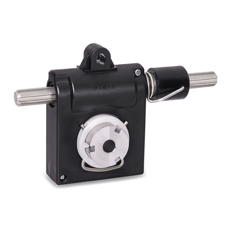
Safety gear F 40 (up to 350 Nm driving torque), permissible door weights in Newton [N]
Shaft diameter up to [mm] 100 x 3 133 x 4 159 x 4,5 168,3 x 4,5 193,7 x 5,4
Door width [m] 3 6 9 3 6 9 3 6 9 3 6 9 3 6 9
Profile thickness of curtain: 20 mm
3 5512 2613 1583 4875 4876 3899 4326 4327 4329 4137 4139 4141 3665 3668 3672
Door height [m] 5 4846 2613 1583 4416 4417 3899 4059 4061 4063 3932 3934 3936 3590 3593 3597
7 4346 2613 1583 4046 4047 3899 3787 3789 3791 3693 3695 3697 3434 3437 3441
Profile thickness of curtain: 30 mm
3 4779 2613 1583 4328 4329 3899 3957 3959 3960 3825 3827 3829 3475 3478 3481
Door height [m] 5 4091 2613 1583 3827 3857 3828 3597 3598 3600 3512 3514 3516 3280 3283 3286
7 3651 2613 1583 3468 3468 3469 3305 3306 3308 3244 3246 3247 3073 3076 3079
Safety gear F 80 (up to 750 Nm driving torque), permissible door weights in Newton [N]
Shaft diameter up to [mm] 133 x 4 159 x 4,5 168,3 x 4,5 193,7 x 5,4 244,5 x 6,3
Door width [m] 3 6 9 3 6 9 3 6 9 3 6 9 3 6 9
Profile thickness of curtain: 20 mm
3 8412 4796 2982 7475 7432 4925 7151 7103 5578 6299 6221 6142 4875 4729 4582
Door width [m] 5 7247 4796 2982 6670 6631 4925 6462 6417 5578 5886 5813 5739 4800 4656 4511
7 6386 4796 2982 5983 5949 4925 5835 5795 5578 5413 5345 5277 4573 4436 4298
9 5739 4796 2982 5437 5406 4925 5324 5287 5251 4996 4933 4871 4320 4190 4060
Profile thickness of curtain: 30 mm
3 7162 4796 2982 6558 6520 4925 6342 6298 5578 5749 5677 5605 4644 4504 4365
Door width [m] 5 5971 4796 2982 5671 5585 4925 5486 5449 5411 5111 5047 4983 4355 4224 4093
7 5170 4796 2982 4930 4902 4873 4839 4806 4773 4573 4516 4459 4011 3891 3770
9 4594 4796 2982 4417 4391 4366 4349 4319 4289 4146 4094 4042 3704 3593 3481
The permissible bending stress in the winding shaft (90% of the yield point for steel St-37.2) is allowed for in the event of safety stop.
The drop distance specified in EN 12604, no. 4.3.4 must not exceed 0.3 m.
Type F 40 F 80
Max. drop distance [m] 0,030 0,046
Lever crank [m] 0,115 0,128
Type F 40: a drop distance of 0.065 m = 6.5 cm is given for a roll diameter of 0.5 m.
Calculation example:
Actual drop distance in m = Max. drop distance x roll diameter =0,030 x 0,5
Lever crank x 2 0,115 x 2
The above data is for the complete rolling door curtain in kg, with 15% allowance for friction. Please observe the permissible load on the roller tube
and the door weight for the safety gear systems.
All values are guide values. No liability can be accepted.
8 | EN © elero GmbH


