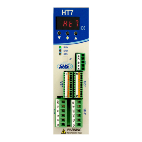
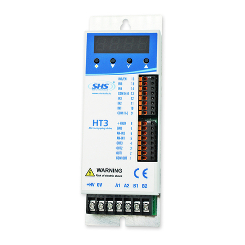
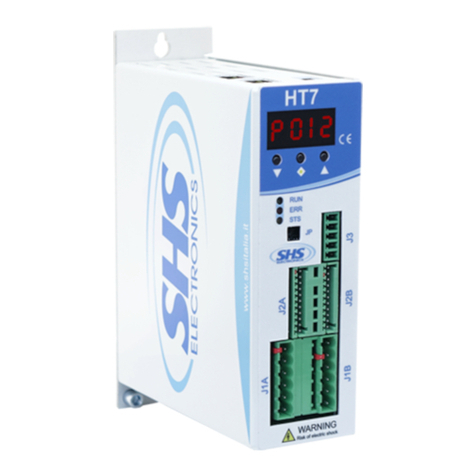
SHS EtherCAT HT7 User manual

HT7
Stepper Motor Drive
EtherCAT User Manual
Manual r06
Company Quality Assurance conforming
S.H.S. s.r.l. Via Fratelli Rosselli 29 - 20027 Rescaldina MI) Italy - Phone +39 0331 466918 - www.shsitalia.it

Index
Introduction 1
Warnings 1
General Info 1
Configuration File 1
Device Control 2
Drive State 3
Device Control Commands 3
Errors 4
Device Errors 4
Communication Errors 4
System Units 5
Operating Modes 5
Overview 5
Profile position mode pp) 6
Overview 6
Controlword Profile Position mode-specific bits 7
Statusword Profile Position mode-specific bits 7
Profile velocity mode pv) 8
Overview 8
Controlword Profile Velocity mode-specific bits 9
Statusword Profile Velocity mode-specific bits 9
Homing mode hm) 10
Overview 10
Controlword Homing mode mode-specific bits 10
Statusword Homing mode mode-specific bits 10
Homing Method 1 Negative Limit Switch with Encoder Index) 11
Homing Method 17 Negative Limit Switch) 11
Homing Method 37 Homing on current position) 11
Encoder Feedback 12
Encoder Mode 0 12
Encoder Mode 1 12
Encoder Mode 2 12
Inputs and Outputs 13
HT7 Ethercat User Guide i

Digital inputs 13
Digital outputs 14
Analog input 14
Analog output 14
EtherCAT communication 15
EtherCAT State Machine 15
Object Dictionary 17
Overview 17
Object Dictionary Overview 17
Object Data Types 18
Object Access Types 19
Objects 19
Device type 0x1000 19
Error Register 0x1001 19
Manufacturer Device Name 0x1008 20
Hardware Version Object 0x1009 20
Software Version Object 0x100A 21
Identity Object 0x1018 21
Error Settings Object 0x10F1 22
Receive PDO 1 Mapping Object 0x1600 23
Receive PDO 256 Mapping Object 0x1700 23
Transmit PDO 1 Mapping Object 0x1A00 24
Transmit PDO 2 Mapping Object 0x1B00 24
Sync Manager Communication Type Object 0x1C00 25
Sync Manager Channel 2 RxPDO) Object 0x1C12 26
Sync Manager Channel 3 TxPDO) Object 0x1C13 27
Phase Current Object 0x2010 28
Phase Current Reduction Object 0x2011 28
Phase Current Reduction Time Object 0x2012 29
Low Noise Mode Object 0x2013 29
Min Frequency Object 0x2018 29
Drive Temperature Object 0x2020 30
Encoder Counts Object 0x2030 30
Encoder Configuration Object 0x2032 31
Encoder Fault Steps Object 0x2034 31
HT7 Ethercat User Guide ii

Digital Inputs Configuration Object 0x2070 32
Digital Inputs Functionalities Object 0x2071 33
Digital Outputs Configuration Object 0x2078 34
Digital Outputs Functionalities Object 0x2079 35
Error Code Object 0x603F 36
Controlword Object 0x6040 36
Statusword Object 0x6041 37
Quick Stop Option Code Object 0x605A 38
Shutdown Option Code Object 0x605B 39
Disable Operation Option Code Object 0x605C 39
Modes of Operation Object 0x6060 40
Modes of Operation Display Object 0x6061 40
Position Demand Value Object 0x6062 41
Position Actual Internal Value Object 0x6063 41
Position Actual Value Object 0x6064 41
Velocity Demand Value Object 0x606B 42
Velocity Actual Value Object 0x606C 42
Velocity Window Object 0x606D 42
Velocity Window Time Object 0x606E 43
DC Link Circuit Voltage Object 0x6079 43
Target Position Object 0x607A 43
Home Offset Object 0x607C 44
Software Position Limit Object 0x607D 44
Polarity Object 0x607E 45
Max Profile Velocity Object 0x607F 46
Profile Velocity Object 0x6081 46
Profile Acceleration Object 0x6083 46
Gear Ratio Object 0x6091 47
Feed Constant Object 0x6092 48
Homing Method Object 0x6098 49
Homing Speeds Object 0x6099 49
Homing Acceleration Object 0x609A 50
Touch Probe Function Object 0x60B8 50
Touch Probe Status Object 0x60B9 51
Touch Probe Position 1 Positive Value Object 0x60BA 51
HT7 Ethercat User Guide iii

Touch Probe Position 1 Negative Value Object 0x60BB 52
Touch Probe 1 Positive Edge Counter Object 0x60D5 52
Touch Probe 1 Negative Edge Counter Object 0x60D6 52
Supported Homing Methods Object 0x60E3 53
Motor Resolution Object 0x60EF 54
Position Demand Internal Value Object 0x60FC 55
Target Velocity Object 0x60FF 55
Supported Drive Modes Object 0x6502 55
HT7 Ethercat User Guide iv

1 Introduction
1.1 Warnings
This document is meant for qualified technical personnel. You must read carefully and understand
the manual, then follow the instruction given here before starting any activities.
1.2 General Info
This document provides the necessary information to use the HT7 stepper motor drive by mean of
EtherCAT communication. It contains descriptions of the architecture, device states, operation
modes, error handling and object dictionary. Wiring schemes and electrical characteristics can be
found on the HT7_HW_MANUAL, available on our website: www.shsitalia.it
1.3 Configuration File
Refere to ESI configuration file “HT7_ECAT_3_05_DC.xml”.
HT7 Ethercat User Guide 1

2 Device Control
The state machine describes the drive states and the possible transition among them. Each state
determines a drive behavior and the accepted control commands. The drive state can be read by
means of the Statusword, while the transitions can be automatic or acted by the Controlword.
Not ready to Switch On state is performed automatically by the driver during startup.
Bold states are stable states and shall be checked by the control device.
Transitions 3 and 4 can only be requested by the control device.
Switch On Disabled can be passed through automatically, the control device has to perform
transition 2 only if needed.
HT7 Ethercat User Guide 2

2.1 Drive State
The current state of the driver can be read by the following bits of the Statusword.
State Statusword (binary) Description
Start xxxx xx0x x000 0000 Bootup
Not ready to Switch On xxxx xx1x x000 0000 Drive is disabled
Switch On Disabled xxxx xx1x x100 0000
Drive initialization completed
Drive disabled
Parameter can be changed
Ready to Switch On xxxx xx1x x010 0001 Drive disabled
Parameter can be changed
Switched On xxxx xx1x x010 0011 Drive disabled
Operation Enabled xxxx xx1x x011 0111
Drive enabled
Motor is powered
No faults
Quickstop Active xxxx xx1x x001 0111
Quickstop is being executed
Drive enabled
Motor is powered
Fault reaction active
when disabled) xxxx xx1x x000 1111 A fault occurred
Drive disabled
Fault reaction active
when enabled) xxxx xx1x x001 1111
A fault occurred
Drive enabled
The fault reaction is being executed
Fault xxxx xx1x x000 1000
A fault occurred
Drive disabled
Parameter can be changed
Table 2-1 Device State Bits on Statusword
2.2 Device Control Commands
A state transition can be caused by an internal event or by a command sent via the Controlword. To
trigger these events, the Controlword bits shall be set as per the following Table 2-2.
Command Controlword (binary) State transitions
Shutdown xxxx xxxx 0xxx x110 2, 6, 8
Switch On xxxx xxxx 0xxx x111 3
Enable operation xxxx xxxx 0xxx 1111 4, 16
Disable voltage xxxx xxxx 0xxx xx0x 7, 9, 10, 12
Quickstop xxxx xxxx 0xxx x01x 7, 10, 11
Disable operation xxxx xxxx 0xxx 0111 5
Fault reset xxxx xxxx 1xxx xxxx 15
Table 2-2 Device Control Commands
HT7 Ethercat User Guide 3

3 rrors
3.1 Device rrors
When the drive detects an error, it generates an error code. The reaction to an error depends on error
type and option code. After execution of the fault reaction, the device changes to fault state and the
drive will be disabled.
The Error Register 0x1001 describes the error happened on the device, a more detailed description
of the error can be read on Error Code Object 0x603F.
3.2 Communication rrors
An abort object will be sent over the network instead of a response to an SDO request if the request
was not successful. Table 3-1 describes the possible abort codes and their causes.
Abort Code Name
0x 0503 0000 Toggle bit has not changed
0x 0504 0000 SDO protocol timeout
0x 0504 0001 Invalid command received
0x 0504 0005 Out of memory
0x 0601 0000 Access to the object not supported
0x 0601 0001 Attempt to read to a write only object
0x 0601 0002 Attempt to write to a read only object
0x 0602 0000 Object not listed in the object directory
0x 0604 0041 Object cannot be mapped to PDO
0x 0604 0042 Number or length of the objects to be mapped exceeds the
PDO length
0x 0604 0043 General parameter incompatibility
0x 0604 0047 General internal parameter incompatibility
0x 0606 0000 Access denied due to a hardware error
0x 0607 0010 Wrong data type or length of the service parameter does not match
0x 0607 0012 Wrong data type or length of the service parameter is too large
0x 0607 0013 Wrong data type or length of the service parameter is too small
0x 0609 0011 Subindex does not exist
0x 0609 0030 Invalid value of the parameter write access only)
0x 0609 0031 Value of the parameter is too large
0x 0609 0032 Value of the parameter is too small
0x 0609 0036 Maximum value is less than minimum value
0x 0800 0000 General error
0x 0800 0020 Data cannot be transferred or saved in the application
0x 0800 0021 Data cannot be transferred or saved in the application due to local
control
HT7 Ethercat User Guide 4

Abort Code Name
0x 0800 0022 Data cannot be transferred or saved in the application due to device
state
0x 0800 0023 Dynamic generating of the object directory failed or no object
directory available
Table 3-1 Abort Codes Descri tion
4 System Units
The drive uses fixed internal drive units to manage the movements, nevertheless user can act on
some parameters in order to have convenient physical units, as explained on this section.
Internal units are described on Table 4-1 below.
Internal Units Definition
Position Steps
Speed Steps/s
Acceleration ms/10,000steps
Table 4-1 Internal Units Definition
Physical units are described on Table 4-2 below.
Internal Units Definition
Position 1 turn
Speed rpm
Acceleration rpm/s
Table 4-2 Physical Units Definition
User can act on the Gear Ratio Object 0x6091 and Feed Constant Object 0x6092 to obtain the
motion values on suitable units for its mechanical system.
5 Operating Modes
5.1 Overview
The drive behavior depends on the activated mode of operation. The mode can be chosen writing
the Modes of O eration object, while the drive provides the Modes of o eration dis lay to identify
the active operation mode.
PDOs, Statusword, Controlword and set-points are mode-specific, so the control device shall
manage the various operation modes correctly.
HT7 drive supports the modes of operation on Table 5-1 and will be explained later:
Mode of operation Abbre iation Code
Profile position mode pp 1
HT7 Ethercat User Guide 5

Mode of operation Abbre iation Code
Profile velocity mode pv 3
Homing mode hm 6
Table 5-1 Su orted o eration modes
The supported modes are listed in the object Su orted drive modes.
5.2 Profile position mode (pp)
5.2.1 Overview
When the drive is in pp mode, the position control loop is closed on the drive side. The control
device can manage the positioning by acting on the objects shown in Figure 5-1 below.
Figure 5-1 Trajectory generator for mode
Set-points handshake is controlled by the Controlword bits new set- oint, as well as the bit set-
oint acknowledgement in the Statusword.
After a set-point is applied to the drive, the control device signals that the set-point is valid by a
rising edge of the new set- oint bit. The drive device sets the set- oint acknowledgement bit and,
afterwards, the drive signals its ability to receive a new set-point clearing the set- oint
acknowledgement bit. An example is shown in Figure 5-2.
HT7 Ethercat User Guide 6

Figure 5-2 Set- oint exam le
5.2.2 Controlword Profile Position mode-specific bits
The profile position mode uses some bits of the Controlword for mode-specific purposes, as
highlighted on Table 5-2 explain the usage of these bits.
Bit Value Definition
4 0 → 1 New Setpoint, start move
60 Target position is an absolute value
1 Target position is a relative value
80 Positioning shall be executed or continued
1 Motor shall be stopped accordingly to halt option code object 0x605D)
Table 5-2 Controlword bits 4, 6 8 in mode
5.2.3 Statusword Profile Position mode-specific bits
The profile position mode uses some bits of the Statusword for mode-specific purposes, Table 5-4
explain the meaning of these bits.
HT7 Ethercat User Guide 7

Bit Value Definition
10 0 Target position not reached
1 Target position reached
12 0 Previous setpoint already processed
1 Previous setpoint still in process, setpoint can be overwritten
13 0 No following error
1 Following error
Table 5-4 Statusword bits 10, 12, 13 in mode
5.3 Profile velocity mode (pv)
5.3.1 Overview
When the drive is in pv mode, the position control loop is closed on the drive side. The control
device can manage the positioning by acting on the objects shown in Figure 5-5 below.
Figure 5-5 Profile velocity mode
The profile velocity mode doesn’t have handshake mechanism contrary to the profile position
mode), every time a parameter is changed, the new value is updated immediately.
HT7 Ethercat User Guide 8

5.3.2 Controlword Profile Velocity mode-specific bits
The profile velocity mode uses Halt bit 8 of the Controlword for mode-specific purposes, as
highlighted on Table 5-5.
Bit Bit 5 Definition
80 The motion shall be executed or continued
1 Motor shall be stopped accordingly to halt option code object 0x605D)
Table 5-5 Controlword bit 8 in v mode
5.3.3 Statusword Profile Velocity mode-specific bits
The profile position mode uses some bits of the Statusword for mode-specific purposes, Table 5-6
explain the meaning of these bits.
Bit Value Definition
10 0 Target velocity not reached
1 Target velocity reached
12 0 Speed is not equal to 0
1 Speed is equal to 0
13 0 Not used
1 Not used
Table 5-6 Statusword bits 10, 12, 13 in v mode
HT7 Ethercat User Guide 9

5.4 Homing mode (hm)
5.4.1 Overview
This operation mode is used to make the drive seek for the zero homing) position. Figure 5-8
shows the objects involved in this functionality. The home position and the zero position are offset
by the home offset. Actually, HT7 drive supports the methods described in the following sections
and available on the object Su orted homing methods.
Figure 5-8 Homing mode function
To select the drive input to have homing, use the object Digital Inputs Configuration 0x2070) and
Digital Inputs Functionalities 0x2071).
5.4.2 Controlword Homing mode mode-specific bits
To start the homing position, the Homing o eration start, bit 4 in the Controlword, must be set. The
motor can be halted during the homing procedure setting the Halt bit in Controlword.
5.4.3 Statusword Homing mode mode-specific bits
The bits of the Statusword listed in Table 5-7 describes the operative status of the drive when in
homing mode.
Bit 13 Bit 12 Bit 10 Definition
0 0 0 Homing procedure in progress
0 0 1 Homing procedure interrupted or not started
0 1 0 Homing is attained, but target is not reached
0 1 1 Homing procedure completed successfully
1 0 0 Homing error occurred, velocity is not 0
1 0 1 Homing error occurred, velocity is 0
1 1 X Reserved
Table 5-7 Statusword bits 10, 12, 13 in homing mode
HT7 Ethercat User Guide 10

5.4.4 Homing Method 1 (Negative Limit Switch with ncoder Index)
After the Homing o eration start bit has been set, the drive starts the motor in CCW direction
toward the negative position), until the negative limit switch is reached, then it moves in positive
direction to disengage the switch. After the switch has been disengaged, the motor start again in
positive direction until the encoder index has been reached. When motor is still, the Position Actual
Value will be set to Home Offset value.
5.4.5 Homing Method 17 (Negative Limit Switch)
After the Homing o eration start bit has been set, the drive starts the motor in CCW direction
toward the negative position), until the negative limit switch is reached, then it moves in positive
direction to disengage the switch. After the switch has been disengaged, the Position Actual Value
will be set to Home Offset value.
5.4.6 Homing Method 37 (Homing on current position)
When the Homing o eration start bit is set, the actual position is set as the home position. This
function does not require the drive to be in operational enabled state. After the homing process the
Position Actual Value will be equal to Home Offset.
HT7 Ethercat User Guide 11

6 ncoder Feedback
A digital encoder sensor can be connected to the drive, both single ended and differential sensors
are accepted; wiring instructions are available into the hardware manual.
The behavior of the drive when the encoder is used is configured by the Encoder Mode sub-index of
the Encoder Configuration Object 0x2032. The available modes are described in the next chapters.
6.1 ncoder Mode 0
When the Encoder Mode sub-index is set to 0, the encoder doesn’t affect the positioning, the
position can be read on Encoder Counts Object 0x2030.
6.2 ncoder Mode 1
If this mode is active, the drive checks whether the difference between the theorical position and the
encoder feedback position is lower than the value set in Encoder Fault Steps Object 0x2034.
When this condition is violated, the drive rise an error in the statusword, based on the active
operating mode, see Table 6-1. The motor keeps running until the target position is reached.User
must take into account that if the stepper motor is in a stall condition, it should be stopped and
restarted in order to exit this condition.
Acti e Mode Statusword flag Encoder Error action Statusword bit
Profile Position Following Error Rise 13
Profile Velocity Speed Rise 13
Table 6-1 Encoder action on statusword
6.3 ncoder Mode 2
If this mode is active, the drive checks whether the difference between the theorical position and the
encoder feedback position is lower than the value set in Encoder Fault Steps Object 0x2034.
When this condition is violated, an error in the statusword, based on the active operating mode, see
Table 6-1. Despite mode 1, the drive stops the motor.
HT7 Ethercat User Guide 12

7 Inputs and Outputs
7.1 Digital inputs
Digital inputs can be mapped to predefined functions or as general-purpose inputs, by mean of the
Digital Inputs Configuration Object 0x2070. By modifying the Digital Inputs Functionalities Object
0x2071, the polarity can be set-up for all the functions, while only the general-purpose inputs can be
masked. Figure 7-1 shows this behavior.
Figure 7-1 Digital In uts usage
HT7 Ethercat User Guide 13

7.2 Digital outputs
Digital outputs OUT1, OUT2 and OUT3) can be mapped as general-purpose outputs, by mean of
the Digital Outputs Configuration Object 0x2078. The value and the mask can be set modifying the
Digital Outputs Functionalities Object 0x2079.
7.3 Analog input
Analog inputs can’t be read or assigned to a function by the control device.
7.4 Analog output
Analog outputs can’t be write or assigned to a function by the control device.
HT7 Ethercat User Guide 14

8 therCAT communication
8.1 therCAT State Machine
The EtherCAT State Machine in Figure 8-1 indicates which functionalities are actually available.
The functions in the different states are described in Table 8-1below. Transitions among states are
described in Table 8-2.
Figure 8-1 EtherCAT Slave State Machine
State Description
INIT
Init state
No communication on the application layer is available.
The master has access only to the DL-information registers
PREOP
Pre-Operational state
Mailbox communication on the application layer available, but no
process data communication available. Master setup cyclic
communication via PDOs
SAFEOP
Safe-Operational state
Mailbox communication on the application layer, process input) data
communication available.
In SafeOp only inputs are evaluated; outputs are kept in ‘safe’ state.
OP
Operational state Process data inputs and outputs are valid.
BOOT
Bootstrap state
No process data communication.
Communication only via mailbox on Application Layer available.
Used for firmware updates.
Table 8-1 EtherCAT State Machine Descri tion
Transition Description
I -> P
Master reads VendorID, ProductCode and RevisionNumber from
EEPROM, and configures DL registers, SyncManager registers for
mailbox communication and initialize DC clock synchronization.
Master requests PreOp state and waits for status confirmation.
HT7 Ethercat User Guide 15
Other manuals for EtherCAT HT7
1
Table of contents
Other SHS DC Drive manuals
Popular DC Drive manuals by other brands
Danfoss
Danfoss VLT HVAC Drive FC 102 operating instructions
Siemens
Siemens SINAMICS G120 CU240B-2 operating instructions
GFA
GFA ELEKTROMAT FS 50.20-40,00 installation instructions
Pentax
Pentax DSI-200 Series user manual
Dodge
Dodge PDNF 306 instruction manual
Eaton
Eaton DA1-32030-20 Series Instruction leaflet
Masterflex
Masterflex I/P Series quick start guide
Just Motion Control
Just Motion Control 2DM556 manual
Electro-Voice
Electro-Voice ID60D-8 Specifications
SOMFY
SOMFY Pergola io Installer's guide
Lenze
Lenze L-force 9400 Mounting instructions
Rockwell Automation
Rockwell Automation Allen-Bradley PowerFlex 4M installation instructions
