manuals.online logo
Brands
  1. Home
  2. •
  3. Brands
  4. •
  5. Festo
  6. •
  7. DC Drive
  8. •
  9. Festo DFPD-Series User manual

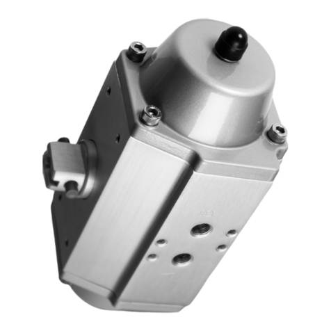
Festo DFPD-Series User manual

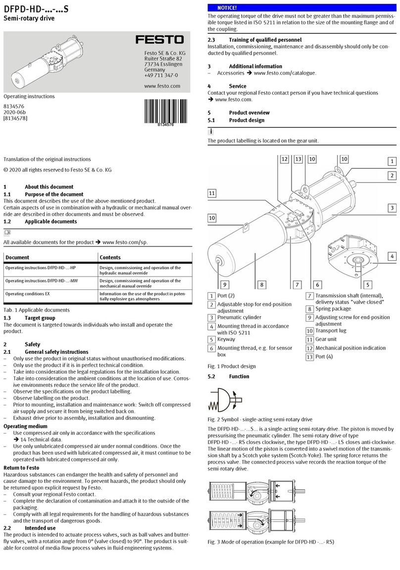
Translation of the original instructions
© 2020 all rights reserved to Festo SE & Co. KG
1 About this document
1.1 Purpose of the document
This document describes the use of the above-mentioned product.
The document contains additional information for the use of the product in safety-
oriented systems (safety handbook in accordance with IEC61508).
1.2 Applicable documents
All available documents for the product èwww.festo.com/sp.
Document Contents
Operating conditions EX Information on the use of the product in poten-
tially explosive gas atmospheres
Certification documents Test certificates for machine safety
Tab. 1 Applicable documents
1.3 Target group
The document is targeted towards individuals who install and operate the
product.
The document is additionally targeted towards individuals who are entrusted with
the planning and application of the product in a safety-oriented system.
1.4 Specified standards
Version
IEC61508-1:2010 IEC61508-7:2010
IEC61508-2:2010 IEC61511:2016
IEC61508-4:2010 –
Tab. 2 Specified standards
2 Safety
2.1 General safety instructions
– Only use the product in original status without unauthorised modifications.
– Only use the product if it is in perfect technical condition.
– Take into consideration the legal regulations for the installation location.
– Take into consideration the ambient conditions at the location of use. Corros-
ive environments reduce the service life of the product.
– Observe the specifications on the product labelling.
– Observe labelling on the product.
– Prior to mounting, installation and maintenance work: Switch off compressed
air supply and secure it from being switched back on.
– Exhaust drive prior to assembly, installation and dismounting.
– Product must be regularly tested by a qualified technician, and the test must
be documented è 9 Maintenance.
– Protect the device from pressure fluctuations. Use overpressure valves and
pressure regulators.
Operating medium
– Use compressed air only in accordance with the specifications
è 14 Technical data.
– Use only unlubricated compressed air under normal conditions. Once the
product has been used with lubricated compressed air, it must continue to be
operated with lubricated compressed air only.
Return to Festo
Hazardous substances can endanger the health and safety of personnel and
cause damage to the environment. To prevent hazards, the product should only
be returned upon explicit request by Festo.
– Consult your regional Festo contact.
– Complete the declaration of contamination and attach it to the outside of the
packaging.
– Comply with all legal requirements for the handling of hazardous substances
and the transport of dangerous goods.
2.2 Intended use
The product is intended to actuate process valves, such as ball valves and butter-
fly valves with a rotation angle from 0° (valve closed) to 180° (depending on the
version).
NOTICE!
The operating torque of the drive must not be greater than the maximum permiss-
ible torque listed in ISO5211 in relation to the size of the mounting flange and of
the coupling.
2.2.1 Information on functional safety
2.2.1.1 Achievable safety classification
The product is suitable for use as an element in a safety-oriented system in
accordance with IEC61511.
– in Low Demand Mode up to SIL2
– in High Demand Mode up to SIL1
Considering the necessary minimum hardware fault tolerance of HFT=1, the
product can also be used up to SIL3 in a redundant execution of the entire sys-
tem.
NOTICE!
The suitability for certain applications can only be determined in connection with
the assessment of further components of the subsystem. These must achieve the
same safety level.
2.2.1.2 Safety function
Single-acting semi-rotary drives DFPD-...-RS/DFPD-...-LS
The element safety function consists of the control valve moving to the switching
position when the compressed air is switched off. It is returned by spring force.
Double-acting semi-rotary drives DFPD-...-RD/DFPD-...-LD
The element safety function consists in the execution of a complete working
stroke (opening or closing the process valve) within a defined time.
2.2.1.3 Operating conditions
– General information on safe operation è 2.1 General safety instructions.
– Periodic tests (function test) è 9 Maintenance.
– Ambient conditions and additional technical specifications
è 14 Technical data.
2.2.1.4 Limitations of use
If used in a safety-oriented system, the service life is limited to 8years subject to
compliance with the operating conditions.
– Recommended interval for a complete function test: 1year
– Maximum permissible interval for a complete function test: 3years
If function tests are negative, maintenance work must be performed immediately.
2.2.1.5 Characteristic values
Safety characteristic (in accordance with
IEC61508)
Value
Probability of dangerous failure on demand
(Probability of Dangerous Failure on Demand)
PFDspec 8.89·10-4
Assumed test interval (Assumed Test Interval) Ti1 a
Confidence level (Confidence Level) 1-á95%
Hardware fault tolerance (Hardware Fault Tolerance) HFT 0
Diagnostic coverage (Diagnostic Coverage) DC 0
Type of subsystem (Type of Sub System) Type A
Mode of operation (Mode of Operation) Low Demand and
High Demand
Degree of detection of dangerous errors by the proof test
(Proof Test Coverage)
PTC 99%
Assumed demands per year (Low Demand Mode)
(Assumed Demands per Year)
nop 1/a
Failure rate for dangerous errors not detected
(Lambda Dangerous Undetected)
ëDU 1.01·10-7/h
Mean time to failure (dangerous)
(Mean Time to Failure dangerous)
MTTFD1.126 a
Low Demand Mode (double-acting)
Failure rate for dangerous errors not detected
(Lambda Dangerous Failure Rate)
ëD3.24·10-7/h
Mean probability of dangerous failure on demand
(Average Probability of Failure on Demand) 1oo1
PFDavg (TI = 1 a) 1.42·10-3
Mean probability of dangerous failure on demand
(Average Probability of Failure on Demand) 1oo2
PFDavg (TI = 1 a) 1.44·10-4
Low Demand Mode (single-acting)
Failure rate for dangerous errors not detected
(Lambda Dangerous Failure Rate)
ëD1.78·10-7/h
8147709
DFPD-...
Semi-rotary drive
8147709
2020-11d
[8147711]
Operating instructions
Festo SE & Co. KG
Ruiter Straße 82
73734 Esslingen
Germany
+49 711 347-0
www.festo.com
Safety characteristic (in accordance with
IEC61508)
Value
Mean probability of dangerous failure on demand
(Average Probability of Failure on Demand) 1oo1
PFDavg (TI = 1 a) 7.80·10-4
Mean probability of dangerous failure on demand
(Average Probability of Failure on Demand) 1oo2
PFDavg (TI = 1 a) 7.87·10-5
High Demand Mode
Assumed demands per year (Assumed Demands per Year) nop 8760/a
Mean frequency of a dangerous failure per hour
(Probability of dangerous Failure per hour)
PFH 1.01·10-7/h
Tab. 3 Safety characteristics
2.3 Training of qualified personnel
Work on the product should only be conducted by qualified personnel.
3 Additional information
– Accessoriesèwww.festo.com/catalogue.
– Spare partsèwww.festo.com/spareparts.
4 Service
Contact your regional Festo contact person if you have technical questions
èwww.festo.com.
5 Product overview
5.1 Product design
1Thread for transport lugs
(DFPD-2300 only)
2Mounting thread for coding pin
3Supply port (4)
4Mounting thread for pneumatic
NAMUR switching valve
5Mounting thread adapter accord-
ing to VDI 3847-2 (only -VDE2)
6End-position adjustment on both
sides
7Mounting thread for process valve
according to ISO 5211
8Coupling for process valve
9Centring ring for mounting on
adapter bridge (only -C-...)
10 Leakage slot
11 Supply port (2) (only -VDE2)
12 Supply port (4) (only -VDE2)
13 Supply port (2)
14 Mounting thread for limit switch or
position sensor
15 Transmission shaft (shaft groove
shows the process valve position –
here closed)
Fig. 1 Product structure (DFPD-2300 as an example)
A shaft projects outward through the housing on both sides. It transmits the reac-
tion torque to a process valve and, if applicable, a limit switch or position sensor.
The end stops can be adjusted in the range of ±5° using the end-position adjust-
ment on both sides 6.
5.2 Function
The piston movement of the semi-rotary drive is converted into a swivel motion of
the transmission shaft by Rack & Pinion kinematics (gear rack pinion).
Double-acting semi-rotary drives
Fig. 2 Symbol for double-acting semi-rotary drive
Pressurisation and exhaust of the cylinder chamber results in an opening/closing
motion of the drive.
Single-acting semi-rotary drives
Fig. 3 Symbol for single-acting semi-rotary drive
Return is by spring force.
Symbol on the rating plate
Type Mode of operation Symbol
DFPD-RD-... double-acting, closes to the right
DFPD-LD-... double-acting, closes to the left
–
DFPD-RS-... single-acting (spring return), closes to the right
DFPD-LS-... single-acting (spring return), closes to the left
Tab. 4 Symbols for mode of operation
6 Transport and storage
WARNING!
Danger of crushing. Danger of shearing.
Body parts can be crushed or severed if the product falls.
• Use appropriate load handling equipment.
• For DFPD-2300: screw suitable transport lugs into the specified threaded
holes. Lift the drive by the transport lugs.
– When dispatching used products: comply with all legal requirements for the
handling of hazardous substances and the transport of dangerous goods. For
return to Festo è 2.1 General safety instructions.
– Remove all attachments.
– Store the product in a cool, dry, UV-protected and corrosion-protected envir-
onment. Ensure that storage times are kept to a minimum.
– For long-term storage: test the function of the product regularly.
– Observe environmental and storage conditions .
– Seal pneumatic ports.
– Protect coupling parts with grease or protective oil.
– Store the product on a level wooden pallet to prevent damage to the coupling
flange.
7 Mounting and installation
7.1 Assembly without adapter bridge
1Semi-rotary drive
2Process valve
Fig. 4 Assembly without adapter bridge
1. Prepare process valve.
Adjust the control shaft of the process valve to implement the desired operat-
ing method for opening and closing.
2. Place the semi-rotary drive on the control shaft of the process valve. The con-
trol shaft must sit in the coupling of the semi-rotary drive (è Fig.1, 8)
without tilting.
3. Mount the semi-rotary drive on the connecting flange of the process valve
using 4 corrosion-resistant screws, retaining rings and nuts (material: CI).
4. Tighten the screws crosswise è Tab. 12 Tightening torques for flange.
7.2 Assembly with adapter bridge
1Semi-rotary drive
2Adapter bridge
3Coupling
4Process valve
Fig. 5 Assembly with adapter bridge
1. Have adapter bridge and coupling ready èwww.festo.com/catalogue.
2. Mount the adapter bridge 2 on the semi-rotary drive.
– Align studs of the adapter bridge lengthwise to the drive.
– Align open side of the adapter bridge with the process valve.
– Do not jam the centring ring in the drilled hole for the adapter bridge.
– Screw in the screws but do not tighten them yet.
3. Prepare process valve.
Adjust the control shaft of the process valve to implement the desired operat-
ing method for opening and closing.
4. Insert the coupling 3. The square of the coupling must sit in the coupling of
the semi-rotary drive without tilting (è Fig.1, 8).
5. Place the semi-rotary drive with adapter bridge and coupling on the control
shaft of the process valve. The square of the process valve must sit in the
coupling without tilting.
6. Mount the adapter bridge on the connecting flange of the process valve using
4 corrosion-resistant screws, retaining rings and nuts (material: VA).
7. Tighten the screws at both the drive and process valve crosswise
è Tab. 12 Tightening torques for flange.
7.3 Pneumatic port
Single-acting semi-rotary drive
1. Prevent corrosive atmosphere in the spring space. If there is a corrosive atmo-
sphere, use a rebreather block.
2. Mount a filter element on the exhaust port 4 (A) to prevent ingress of dirt.
Type Supply port Effect
DFPD-RS-... 2 Air supply; always connected
DFPD-LS-... 4 Pressurisation of spring space
Tab. 5 Supply port for single-acting semi-rotary drive
Double-acting semi-rotary drive
Type Supply port Effect1)
2 Air supply direction of rotation anti-clockwiseDFPD-RD-...
4 Air supply direction of rotation clockwise
2 Air supply direction of rotation clockwiseDFPD-LD-...
4 Air supply direction of rotation anti-clockwise
1) viewed from the connection point of the accessories
Tab. 6 Supply port for double-acting semi-rotary drive
8 Commissioning
Requirements
– The drive is fully mounted and connected.
Commissioning the drive
1. Pressurise drive slowly.
2. Check correct function at low travel speed.
– Direction of rotation of drive
– Position of process valve
9 Maintenance
9.1 General
– Low Demand Mode:
When used as intended, the product is maintenance-free.
– High Demand Mode DFPD-...-T4
Grease the product again after 20,000 switching cycles.
– High Demand Mode DFPD-...-T6
For safety-oriented applications, replace consumable parts after max. 20,000
switching cycles.
9.2 Proof test (Proof Test)
The proof test consists of a Full Stroke test of the drive. Here, the complete rota-
tion of the shaft is checked at the connection to the process valve dependent on
the switching position of the control valve. The switching position of the shaft can
be determined visually (position of the shaft groove), using a position sensor or
using another suitable auxiliary means.
• Perform the proof test at least once in every 3 years.
During the proof test, the safety of the application must be ensured.
1. Trigger rotation of the shaft at the control valve.
2. Measure the time until the semi-rotary drive has performed a complete rota-
tion of the shaft.
ÄThe test is successful if the semi-rotary drive completes the movement
within the switching time intended for control by the control valve.
3. Check the drive externally (visual inspection).
ÄThe test is successful if no defect, leakage, or contamination is detected.
4. Document test results.
10 Malfunctions
NOTICE!
Repairs to the product are not permissible. In the event of malfunctions or failure:
Replace the product and let Festo know about the failure. Return defective
products to Festo.
Fault description Cause Remedy
Drive does not move in the
desired direction
Compressed air connections
connected incorrectly
Correct the tubing connection
Tab. 7 Malfunctions
11 Modification
11.1 Replacing the spring package
1Screws
2Washers
3Toothed discs
4Cover
5Seal
6Springs
7End-position screws
Fig. 6 Replacing the spring package
WARNING!
Risk of injury from flying objects.
A faulty spring package can result in the cover being ejected during disassembly
and causing injury.
• If the cover is still under spring force when the gap width is reached, do not
proceed with the disassembly.
• Replace the actuator.
Requirements
– Mounting position is vertical. Drive is secured to prevent tilting.
– Drive is removed è 12 Dismounting.
1. Unscrew end position screws.
ÄDrive is in neutral position.
2. Loosen screws crosswise until the gap width is reached.
Ä– Cover is no longer under spring force.
– Gap width between cover and drive: ≤6mm
3. Unscrew screws completely.
4. Remove cover.
ÄSpring package can now be replaced.
5. Remove springs.
6. Insert new springs in the desired configuration.
7. Mount cover. Observe correct position of the seal.
8. Insert the screws and tighten them crosswise .
11.2 Configuring the spring package
The configuration of the spring package is different depending on the nominal
operating pressure.
1Left
2Right
3Spring position
Fig. 7 Configuring the spring package
Spring positionSpring configura-
tion Left Right
Number of springs
[–] – – 0
[20] 2-5 2-5 4
[25] 2-5 2-4-6 5
[30] 2-4-6 2-4-6 6
[35] 2-4-6 1-3-4-6 7
[40] 1-3-4-6 1-3-4-6 8
[45] 1-3-4-6 1-3-4-5-6 9
[50] 1-3-4-5-6 1-3-4-5-6 10
[55] 1-3-4-5-6 1-2-3-4-5-6 11
[60] 1-2-3-4-5-6 1-2-3-4-5-6 12
Tab. 8 Spring configuration
12 Dismounting
1. Switch off the energy supply (compressed air, electricity).
2. Loosen the pneumatic connections.
3. Remove external attachments.
4. Undo the retaining screws of the drive at the process valve and remove the
drive.
13 Disposal
ENVIRONMENT!
Dispose of the product and packaging according to the applicable provisions of
environmentally sound recycling.
14 Technical data
General information DFPD-...-[]-... DFPD-...-T4-... DFPD-...-T6-...
Standard connection to valve
body
ISO5211
Cushioning none
Mounting position any
Design Gear rack/pinion
Ambient temperature [°C] –20…+80 0…+150 –50…+60
Valve connection conforms to
standard
VDI/VDE3845 (NAMUR)
Operating medium Compressed air to ISO 8573-1:2010[7:4:4]
Note on the
operating medium
Pressure dew point at least 10°C below outside temperat-
ure, lubricated operation possible (required in further oper-
ation)
Operating pressure [MPa] 0.2…0.8 0.3…0.8 0.3…0.8
[psi] 29…116 43.5…116 43.5…116
[bar] 2…8 3…8 3…8
Swivel angle
DFPD-…-90 [°] 0…90
DFPD-…-120 [°] 0…120
DFPD-…-135 [°] 0…135
DFPD-…-180 [°] 0…180
End-position adjustment
range
[°] _5
Material
Housing Anodised wrought aluminium alloy
Cover Coated die-cast aluminium
Anodised die-cast aluminium (only DFPD-...-C)
Shaft Nickel-plated steel
Stainless steel (only DFPD-...-R3)
Screws Stainless steel
Seal NBR FKM FVMQ
Tab. 9 Technical data – General
Nominal operating pressure
Type [MPa] [psi] [bar]
DFPD-…-RD, DFPD-…-LD 0.55 79.75 5.5
DFPD-…-…S-20 0.2 29 2.0
DFPD-…-…S-25 0.25 36.25 2.5
Type [MPa] [psi] [bar]
DFPD-…-…S-30 0.3 43.5 3.0
DFPD-…-…S-35 0.35 50.75 3.5
DFPD-…-…S-40 0.4 58 4.0
DFPD-…-…S-45 0.45 65.25 4.5
DFPD-…-…S-50 0.5 72.5 5.0
DFPD-…-…S-55 0.55 79.75 5.5
DFPD-…-…S-60 0.6 87 6.0
Tab. 10 Nominal operating pressure
Air consumption
Type Air consumption per cycle at 0.6MPa
(87 psi, 6 bar) operating pressure1)
DFPD-10-RP-90-D [l] 1.0
DFPD-20-RP-90-D [l] 1.8
DFPD-20-RP-90-S [l] 0.8
DFPD-40-RP-90-D [l] 3.4
DFPD-40-RP-90-S [l] 1.5
DFPD-40-RP-180-D [l] 5.2
DFPD-60-RP-90-D [l] 5.7
DFPD-60-RP-90-S [l] 2.4
DFPD-80-RP-90-D [l] 7.4
DFPD-80-RP-90-S [l] 3.1
DFPD-120-RP-90-D [l] 10.4
DFPD-120-RP-90-S [l] 4.3
DFPD-120-RP-180-D [l] 12.8
DFPD-160-RP-90-D [l] 14.0
DFPD-160-RP-90-S [l] 5.9
DFPD-240-RP-90-D [l] 20.3
DFPD-240-RP-90-S [l] 8.6
DFPD-240-RP-180-D [l] 25.5
DFPD-300-RP-90-D [l] 26.4
DFPD-300-RP-90-S [l] 11.0
DFPD-480-RP-90-D [l] 40.5
DFPD-480-RP-90-S [l] 17.2
DFPD-480-RP-180-D [l] 61.4
DFPD-700-RP-90-D [l] 58.8
DFPD-700-RP-90-S [l] 24.5
DFPD-900-RP-90-D [l] 75.9
DFPD-900-RP-90-S [l] 34.5
DFPD-1200-RP-90-D [l] 105.0
DFPD-1200-RP-90-S [l] 43.5
DFPD-2300-RP-90-D [l] 204.0
DFPD-2300-RP-90-S [l] 84.4
1) Theoretical value for a complete swivel motion (0° - max. swivel angle - 0°)
Tab. 11 Air consumption per cycle
Flange type F03 F04 F05 F07 F10 F12 F14 F16
Tightening torque [Nm] 5…6 9 …
10
22 …
24
46 …
50
80 …
84
190 …
200
370 …
390
Tab. 12 Tightening torques for flange
Type Thread size Tightening torque [Nm]
DFPD-10/-20 M5 6…8
DFPD-40/-60/-80 M6 10…11
DFPD-120/-160/-240 M8 22…25
DFPD-300/-480/-700 M10 38…43
DFPD-900 M12 60…70
DFPD-1200 M14 70…80
DFPD-2300 M16 115…125
Tab. 13 Tightening torques for cover screws

Other manuals for DFPD-Series

5

This manual suits for next models

4

Other Festo DC Drive manuals

Festo EMCA-EC-67 CO Series User manual

Festo

Festo EMCA-EC-67 CO Series User manual

Festo DDLI-25 User manual

Festo

Festo DDLI-25 User manual

Festo DNCE-***-LAS User manual

Festo

Festo DNCE-***-LAS User manual

Festo DFPI ND2P-E-NB3 Series User manual

Festo

Festo DFPI ND2P-E-NB3 Series User manual

Festo DGC-8 Series User manual

Festo

Festo DGC-8 Series User manual

Festo SLG-8 Series User manual

Festo

Festo SLG-8 Series User manual

Festo DRRD Series User manual

Festo

Festo DRRD Series User manual

Festo DFPI Series User manual

Festo

Festo DFPI Series User manual

Festo TP 1422 Operation instructions

Festo

Festo TP 1422 Operation instructions

Festo ERMO User manual

Festo

Festo ERMO User manual

Festo CMMT-ST-C8-1C-...-S0 Series User manual

Festo

Festo CMMT-ST-C8-1C-...-S0 Series User manual

Festo DSR-10-180-P User manual

Festo

Festo DSR-10-180-P User manual

Festo DRD Series User manual

Festo

Festo DRD Series User manual

Festo DNG Series Setup guide

Festo

Festo DNG Series Setup guide

Festo DGCI Series User manual

Festo

Festo DGCI Series User manual

Festo EMCA-EC-67 CO Series User manual

Festo

Festo EMCA-EC-67 CO Series User manual

Festo DGC Series User manual

Festo

Festo DGC Series User manual

Festo ELCC-TB-KF Parts list manual

Festo

Festo ELCC-TB-KF Parts list manual

Festo DAPS Series User manual

Festo

Festo DAPS Series User manual

Festo DSM-6 User manual

Festo

Festo DSM-6 User manual

Festo EMCS-ST User manual

Festo

Festo EMCS-ST User manual

Festo DFPI-...D2P-C1V-NB3P series User manual

Festo

Festo DFPI-...D2P-C1V-NB3P series User manual

Festo DRRD-...-P..E Series User manual

Festo

Festo DRRD-...-P..E Series User manual

Festo DFPI-100-***-E-P User manual

Festo

Festo DFPI-100-***-E-P User manual

Popular DC Drive manuals by other brands

Danfoss VLT OneGearDrive operating instructions

Danfoss

Danfoss VLT OneGearDrive operating instructions

Lenze 8200 vector Mounting instructions

Lenze

Lenze 8200 vector Mounting instructions

Danfoss VACON 3000 Application guide

Danfoss

Danfoss VACON 3000 Application guide

WEG DeviceNet CFW500 user manual

WEG

WEG DeviceNet CFW500 user manual

Moons' MSST5-S user manual

Moons'

Moons' MSST5-S user manual

Eaton Crouse-hinds series Installation & maintenance information

Eaton

Eaton Crouse-hinds series Installation & maintenance information

Meade LXD 650 instruction manual

Meade

Meade LXD 650 instruction manual

Danfoss VLT AQUA Drive FC 202 Programming guide

Danfoss

Danfoss VLT AQUA Drive FC 202 Programming guide

Toshiba Tosvert VF-A5 instruction manual

Toshiba

Toshiba Tosvert VF-A5 instruction manual

KB Electronic KBVF Series Installation and Operation Manual Supplemental Information

KB Electronic

KB Electronic KBVF Series Installation and Operation Manual Supplemental Information

Oray HCM3 RB1 manual

Oray

Oray HCM3 RB1 manual

Rhymebus RM6F2 Series Operation manual

Rhymebus

Rhymebus RM6F2 Series Operation manual

WEG CFW-11 Series manual

WEG

WEG CFW-11 Series manual

BENSHAW RSi H2 Series instruction manual

BENSHAW

BENSHAW RSi H2 Series instruction manual

ELMARK elmatic ED2000 manual

ELMARK

ELMARK elmatic ED2000 manual

Allen-Bradley PowerFlex 70 installation instructions

Allen-Bradley

Allen-Bradley PowerFlex 70 installation instructions

SOMFY Sonesse Ultra 50 RTS Universal Quick Programming Guide

SOMFY

SOMFY Sonesse Ultra 50 RTS Universal Quick Programming Guide

KaVo EWL 4452 operating instructions

KaVo

KaVo EWL 4452 operating instructions

manuals.online logo
manuals.online logoBrands
  • About & Mission
  • Contact us
  • Privacy Policy
  • Terms and Conditions

Copyright 2025 Manuals.Online. All Rights Reserved.