NGI N68000 Series User manual

Hunan Next Generation Instrumental T&C Tech. Co., Ltd.
NGI lNGI N68000 Series High Power DC Electronic Load
N68000 Series High Power DC Electronic
Load
User Manual
©Copyright Hunan Next Generation Instrumental T&C Tech. Co., Ltd.
Version: V20211228

Hunan Next Generation Instrumental T&C Tech. Co., Ltd.
NGI lNGI N68000 Series High Power DC Electronic Load
Contents
CONTENTS...................................................................................................................... 0
1 PREFACE.......................................................................................................................1
2 SAFETY INSTRUCTIONS............................................................................................... 2
2.1 Safety Notes......................................................................................................2
2.2 Safety Symbols..................................................................................................2
3 PRODUCT.....................................................................................................................3
3.1.1 Brief Introduction.................................................................................. 3
3.1.2 Features................................................................................................. 3
3.2 Overview...........................................................................................................4
3.2.1 N68000 Series Lineup............................................................................4
3.2.2 Package Contents and Accessories........................................................5
3.2.3 Appearance & Dimension......................................................................5
3.3 Front Panel Introduction.................................................................................. 6
3.4 Rear Panel Introduction....................................................................................7
3.5 Installation Instruction..................................................................................... 7
3.5.1 AC Input................................................................................................. 7
3.5.2 Power-on Self Test................................................................................. 8
3.6 Connection....................................................................................................... 9
3.6.1 Input Connection...................................................................................9
3.6.2 Control Connection............................................................................... 9
3.6.3 Sense Connection................................................................................ 10
3.6.4 Low Voltage Test Connection.............................................................. 11
3.6.5 Multiple Devices Parallel Connection..................................................12
4 FUNCTIONS AND FEATURES......................................................................................13
4.1 Control Mode................................................................................................. 13
4.2 Constant Current Mode (CC Mode)................................................................13
4.3 Constant Voltage Mode (CV Mode)................................................................13
4.4 Constant Resistance Mode (CR Mode)...........................................................14
4.5 Constant Power Mode (CP Mode)..................................................................15
4.6 Dynamic Mode (TRAN)................................................................................... 15
4.6.1 Continuous (CONT)..............................................................................16
4.6.2 Pulse (PULSE).......................................................................................16
4.6.3 Toggle (TOGGLE).................................................................................. 17
4.7 Auto Test Function..........................................................................................17
4.8 Discharge Test.................................................................................................18
4.9 Charge Test..................................................................................................... 18
4.10 ESR Measurement (Optional).......................................................................19
4.11 Over Current Protection Test (OCP Test)...................................................... 19

Hunan Next Generation Instrumental T&C Tech. Co., Ltd.
NGI lNGI N68000 Series High Power DC Electronic Load
4.12 Input Control................................................................................................ 19
4.12.1 On/Off................................................................................................19
4.12.2 Short-circuit....................................................................................... 20
4.12.3 Von/Voff............................................................................................ 20
4.12.4 Load Time.......................................................................................... 21
4.12.5 Programmable Protection................................................................. 22
4.13 Protection Function...................................................................................... 22
4.14 Slew Rate and Minimum Transition Time.................................................... 24
4.15 Save and Recall............................................................................................. 24
4.16 Power-off Memory....................................................................................... 25
4.17 Language...................................................................................................... 25
4.18 Control and Monitor.....................................................................................26
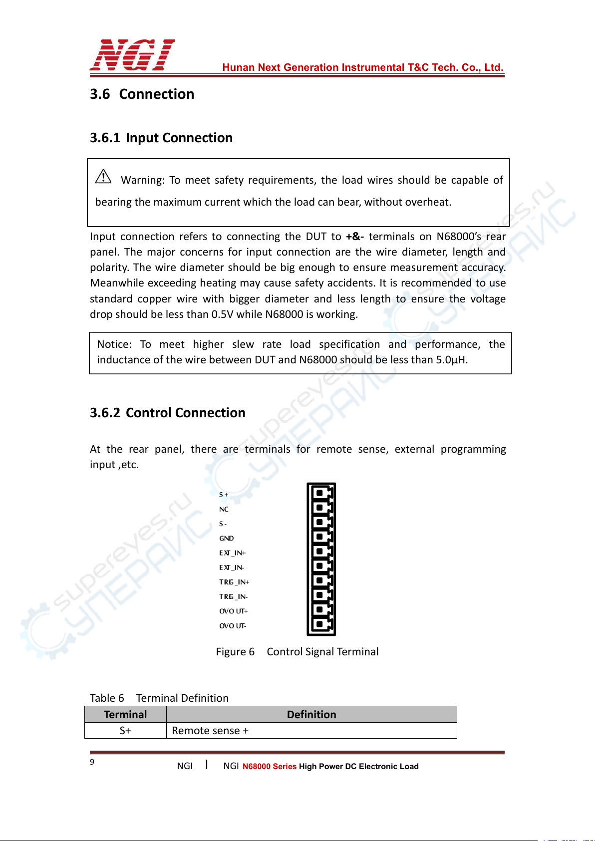
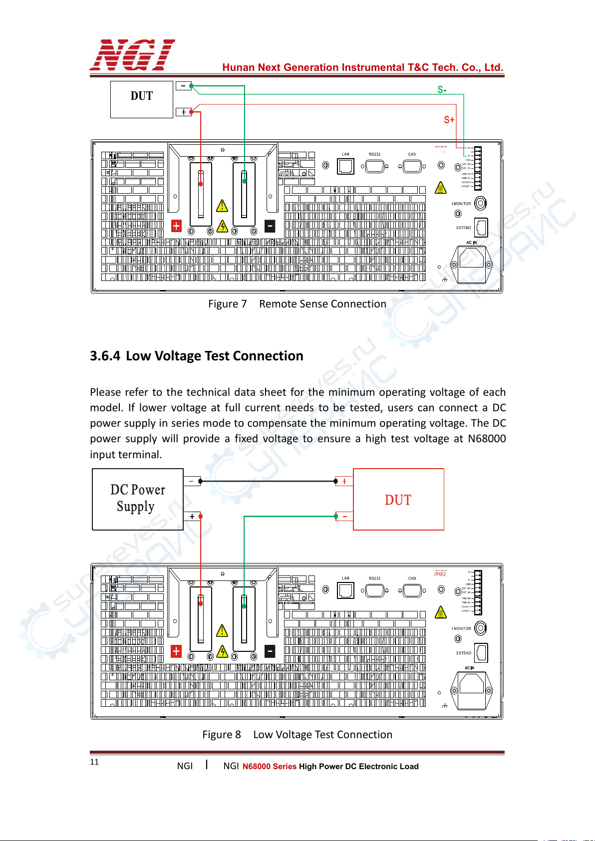
4.18.1 Remote Sense....................................................................................26
4.18.2 Current Monitoring Output...............................................................26
4.18.3 External Programming Input............................................................. 26
4.18.4 External Trigger Input........................................................................ 27
4.19 Factory Reset................................................................................................ 27
5 LOCAL OPERATION.................................................................................................... 28
5.1 Button............................................................................................................. 28
5.1.1 Function Button...................................................................................28
5.1.2 Compound Button............................................................................... 29
5.1.3 Numeric Button................................................................................... 29
5.1.4 Knob.....................................................................................................30
5.2 LCD Screen...................................................................................................... 30
5.2.1 Monitor Interface................................................................................ 30
5.2.2 Status Information...............................................................................30
5.3 Menu.............................................................................................................. 31
5.4 Setting.............................................................................................................33
5.4.1 System Setting..................................................................................... 33
5.4.2 Application Setting.............................................................................. 34
5.4.3 Protection Setting................................................................................35
5.4.4 Factory Reset....................................................................................... 36
6 OPERATION GUIDELINE............................................................................................ 38
6.1 Static Operation..............................................................................................38
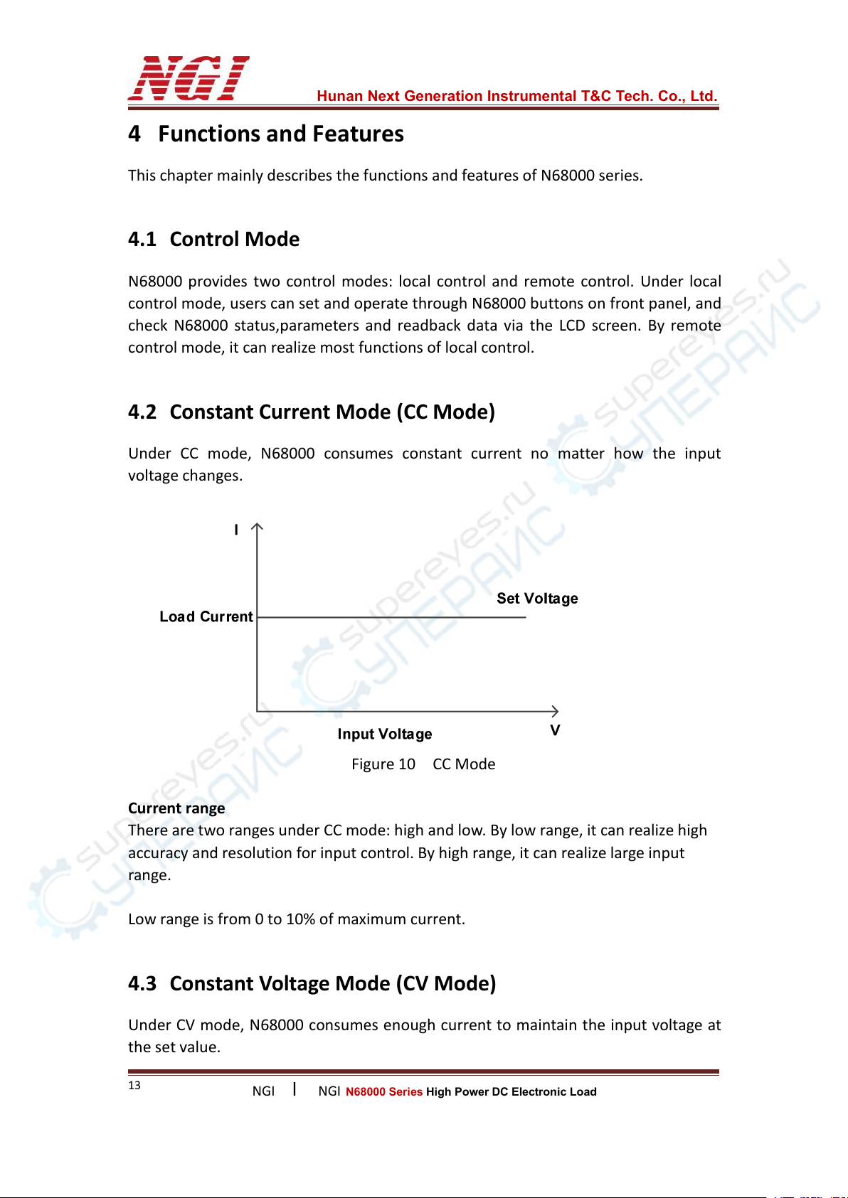
6.1.1 Constant Current (CC)..........................................................................38
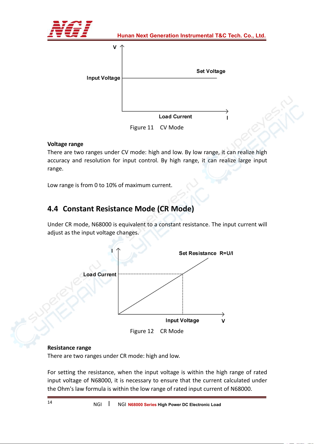
6.1.2 Constant Voltage (CV)..........................................................................40
6.1.3 Constant Resistance (CR).....................................................................41
6.1.4 Constant Power (CP)............................................................................43
6.2 Dynamic Operation.........................................................................................45
6.2.1 CCD Mode Selection............................................................................ 45
6.2.2 Range Selection................................................................................... 46
6.2.3 Operation Mode Selection.................................................................. 46

Hunan Next Generation Instrumental T&C Tech. Co., Ltd.
NGI lNGI N68000 Series High Power DC Electronic Load
6.2.4 Parameter Setting................................................................................46
6.3 Auto Test.........................................................................................................47
6.3.1 SEQ Edit............................................................................................... 47
6.3.2 Starting Auto Test................................................................................ 50
6.4 Capacity Test...................................................................................................51
6.4.1 Discharge............................................................................................. 52
6.4.2 Charge..................................................................................................54
6.5 ESR Test (Optional)......................................................................................... 56
6.6 OCP Test..........................................................................................................58
6.7 MPPT Test....................................................................................................... 60
7 MAINTENANCE AND SELF-INSPECTION....................................................................62
7.1 Regular Maintenance..................................................................................... 62
7.2 Fault Self-inspection....................................................................................... 62
8 MAIN TECHNICAL DATA............................................................................................ 63

Hunan Next Generation Instrumental T&C Tech. Co., Ltd.
NGI lNGI N68000 Series High Power DC Electronic Load
1
1 Preface
Dear Customers,
First of all, we greatly appreciate your choice of N68000 series DC electronic load
(N68000 for short). We are also honored to introduce our company, Hunan Next
Generation Instrumental T&C Tech. Co., Ltd.( NGI for short).
About Company
NGI is a professional manufacturer of intelligent equipment and test & control
instruments, committed to developing, manufacturing battery simulators, power
supplies, electronic loads, and many more instruments. The products can be widely
used in the industries of battery, power supply, fuel cell, consumer electronics, new
energy vehicle, semiconductor, etc.
NGI maintains close cooperation with many universities and scientific research
institutions, and maintains close ties with many industry leaders. We strive to
develop high-quality, technology-leading products, provide high-end technologies,
and continue to explore new industry measurement and control solutions.
About User Manual
This manual is applied to N68000 series DC electronic load, including installation,
operation, specifications and other detailed information. The copyright of the
manual is owned by NGI. Due to the upgrade of instrument, this manual may be
revised without notice in future versions.
This manual has been reviewed carefully by NGI for the technical accuracy. The
manufacturer declines all responsibility for possible errors in this operation manual,
if due to misprints or errors in copying. The manufacturer is not liable for
malfunctioning if the product has not correctly been operated.
To ensure the safety and correct use of N68000, please read this manual carefully,
especially the safety instructions.
Please keep this manual for future use.
Thanks for your trust and support.

Hunan Next Generation Instrumental T&C Tech. Co., Ltd.
NGI lNGI N68000 Series High Power DC Electronic Load
2
2 Safety Instructions
In the operation and maintenance of the instrument, please strictly comply with the
following safety instructions. Any performance regardless of attentions or specific
warnings in other chapters of the manual may impair the protective functions
provided by the instrument.
NGI shall not be liable for the results caused by the neglect of those instructions.
2.1 Safety Notes
Confirm the AC input voltage before supplying power.
Reliable grounding: Before operation, the instrument must be reliably grounded
to avoid the electric shock.
Confirm the fuse: Ensure to have installed the fuse correctly.
Do not open the chassis: The operator cannot open the instrument chassis.
Non-professional operators are not allowed to maintain or adjust it.
Do not operate under hazardous conditions: Do not operate the instrument
under flammable or explosive conditions.
Confirm the working range: Make sure the DUT is within N68000’s rated range.
2.2 Safety Symbols
Please refer to the following table for definitions of international symbols used on
the instrument or in the user manual.
Table 1
Symbol
Definition
Symbol
Definition
DC (direct current)
N
Null line or neutral line
AC (alternating current)
L
Live line
AC and DC
I
Power-on
Three-phase current
Power-off
Ground
Back-up power
Protective ground
Power-on state
Chassis ground
Power-off state
Signal ground
Risk of electric shock
WARNING
Hazardous sign
High temperature
warning
Caution
Be careful
Warning

Hunan Next Generation Instrumental T&C Tech. Co., Ltd.
NGI lNGI N68000 Series High Power DC Electronic Load
3
3 Product
3.1.1 Brief Introduction
N68000 series is developed based on NGI's years of experience in testing for power
supply, car charger, battery and supercapacitor. It is with high accuracy, high
reliability and high cost performance.It has CC, CV, CP and CR mode.
N68000 series supports SEQ test, dynamic test, charge test, discharge test, OCP test,
etc. The power range covers from 2.4kW to 14.4kW.
3.1.2 Features
Power range: 2.4kW to 14.4kW
Voltage range: 150V/600V/1000V
Operation modes: CC/CV/CR/CP
High power density, minimizing space occupation
Transient over-power loading capability
CR/CP function supported by hardware
Charge test, Discharge test and OCP test
Built-in ESR test function(Optional)
Editable rise and fall slew rate
Editable Von/Voff
Programmable sequence test function(SEQ), up to 100 groups sequence files, up
to 50 steps per file
Comprehensive MOS protection
Multiple protection: OCP, OVP, OTP, OPP and reverse polarity warning
Analog programming interface(APG), current monitoring interface, and
remote/local trigger function
Multiple communication interfaces: LAN/RS232/CAN

Hunan Next Generation Instrumental T&C Tech. Co., Ltd.
NGI lNGI N68000 Series High Power DC Electronic Load
4
3.2 Overview
3.2.1 N68000 Series Lineup
Table 2
Model
Specification
Model
Specification
N68024-150-200
2.4kW/150V/200A
N68036-150-300
3.6kW/150V/300A
N68024-150-060
2.4kW/150V/60A
N68036-150-090
3.6kW/150V/90A
N68024-600-020
2.4kW/600V/20A
N68036-600-030
3.6kW/600V/30A
N68024-600-060
2.4kW/600V/60A
N68036-600-090
3.6kW/600V/90A
N68024-1000-020
2.4kW/1000V/20A
N68036-1000-030
3.6kW/1000V/30A
N68024-1000-060
2.4kW/1000V/60A
N68036-1000-090
3.6kW/1000V/90A
N68048-150-400
4.8kW/150V/400A
N68060-150-500
6kW/150V/500A
N68048-150-120
4.8kW/150V/120A
N68060-150-150
6kW/150V/150A
N68048-600-040
4.8kW/600V/40A
N68060-600-050
6kW/600V/50A
N68048-600-120
4.8kW/600V/120A
N68060-600-150
6kW/600V/150A
N68048-1000-040
4.8kW/1000V/40A
N68060-1000-50
6kW/1000V/50A
N68048-1000-120
4.8kW/1000V/120A
N68060-1000-150
6kW/1000V/150A
N68072-150-600
7.2kW/150V/600A
N68084-150-700
8.4kW/150V/700A
N68072-150-180
7.2kW/150V/180A
N68084-150-210
8.4kW/150V/210A
N68072-600-060
7.2kW/600V/60A
N68084-600-070
8.4kW/600V/70A
N68072-600-180
7.2kW/600V/180A
N68084-600-210
8.4kW/600V/210A
N68072-1000-060
7.2kW/1000V/60A
N68084-1000-070
8.4kW/1000V/70A
N68072-1000-180
7.2kW/1000V/180A
N68084-1000-210
8.4kW/1000V/210A
N68096-150-800
9.6kW/150V/800A
N68108-150-900
10.8kW/150V/900A
N68096-150-240
9.6kW/150V/240A
N68108-150-270
10.8kW/150V/270A
N68096-600-080
9.6kW/600V/80A
N68108-600-090
10.8kW/600V/90A
N68096-600-240
9.6kW/600V/240A
N68108-600-270
10.8kW/600V/270A
N68096-1000-080
9.6kW/1000V/80A
N68108-1000-090
10.8kW/1000V/90A
N68096-1000-240
9.6kW/1000V/240A
N68108-1000-270
10.8kW/1000V/270A
N68120-150-1000
12kW/150V/1000A
N68132-150-1100
13.2kW/150V/1100A
N68120-150-300
12kW/150V/300A
N68132-150-330
13.2kW/150V/330A
N68120-600-100
12kW/600V/100A
N68132-600-110
13.2kW/600V/110A
N68120-600-300
12kW/600V/300A
N68132-600-330
13.2kW/600V/330A
N68120-1000-100
12kW/1000V/100A
N68132-1000-110
13.2kW/1000V/110A
N68120-1000-300
12kW/1000V/300A
N68132-1000-330
13.2kW/1000V/330A
N68144-150-1200
14.4kW/150V/1200A
N68144-150-360
14.4kW/150V/360A
N68144-600-120
14.4kW/600V/120A
N68144-600-360
14.4kW/600V/360A
N68144-1000-120
14.4kW/1000V/120A
N68144-1000-360
14.4kW/1000V/360A

Hunan Next Generation Instrumental T&C Tech. Co., Ltd.
NGI lNGI N68000 Series High Power DC Electronic Load
5
For other specifications, please contact NGI.
3.2.2 Package Contents and Accessories
After receiving N68000, please check the instrument according to the following
steps:
1. Check whether the instrument is damaged during transportation. If any severe
damage to the package, please contact NGI or our authorized distributor.
2. Check accessories.
3. Make sure the the following accessories are attached.
Table 3
N68000 Accessories
Instructions
Power cord and fuse
For AC power connection
RS232 cable
For RS232 communication
Ethernet cable
For Ethernet connection
USB flash drive
User manual, software & technical information
If any loss or damage, please contact NGI or our authorized distributor.
4. Check the whole instrument. If N68000 chassis is damaged or has abnormal
operation, please contact NGI or our authorized distributor.
3.2.3 Appearance & Dimension
C V
RangeShor t
C R
C C
C P Menu
TRAN
On Off/ Ente r
2 3
4560
7 8 9
1
ESC
Programmable DC Electronic Load
OCP Sa ve
Auto Di schar ge Charge P ROT-CLR
ESR Recall
Trigger
FUNCTION ENTRY
N68036-150-300 150V/300A/3.6kW
Figure 1 Front Panel Dimension(mm)

Hunan Next Generation Instrumental T&C Tech. Co., Ltd.
NGI lNGI N68000 Series High Power DC Electronic Load
6
Figure 2 Rear Panel Dimension(mm)
Figure 3 Side Dimension(mm)
3.3 Front Panel Introduction
C V
RangeShor t
C R
C C
C P Menu
TRAN
On Off/ Ente r
2 3
4560
7 8 9
1
ESC
Programmable DC Electronic Load
OCP S ave
Auto Discharge Char ge PROT-CLR
ESR Recall
Trigger
FUNCTION ENTRY
N68036-150-300 150V/300A/3.6kW
Figure 4 Front Panel
Table 4
Number
Name
1
Power switch
2
Screen
3
Function buttons
4
Numeric buttons
5
Knob

Hunan Next Generation Instrumental T&C Tech. Co., Ltd.
NGI lNGI N68000 Series High Power DC Electronic Load
7
3.4 Rear Panel Introduction
Figure 5 Rear Panel
Table 5
3.5 Installation Instruction
N68000 dissipates heat through the built-in fans. When installing, please make sure
there is a gap of at least 20cm between N68000 and other objects for air circulation.
3.5.1 AC Input
The power cord is a 3-core wire with grounding protection. Please use a suitable
socket for operation. The power cord also matches your local voltage and plug type.
If it is not matched, please contact NGI.
Number
Name
1
Input terminal (+, -)
2
LAN port
3
RS232 interface
4
CAN interface
5
AC power socket
6
Power module extension port
7
Current output monitoring interface
8
Control signal terminal

Hunan Next Generation Instrumental T&C Tech. Co., Ltd.
NGI lNGI N68000 Series High Power DC Electronic Load
8
3.5.2 Power-on Self Test
Before power-on, please make sure the following.
1) The nominal voltage of the AC input socket should be in the correct range.
2) The power cord is plugged into AC input socket.
After switched on, N68000 will start power-on self test. If no error is found, the LCD
screen will display the below CC interface.
Figure 6 CC Interface
In case of test failure, please record the error information and contact NGI for
support.
If N68000 cannot be started properly, please refer to the following steps.
1) Check whether the power cord is properly connected.
2) Check whether the power is switched on.
3) Check whether the fuse is burned out.
If yes, please replace it.
Please use the proper fuse.
When replacing, please open the plastic cover at the AC power socket.
For more support, please contact NGI.
Warning: The three-core power cord provides chassis grounding. Before
operating on N68000, please make sure N68000 is well grounded.

Hunan Next Generation Instrumental T&C Tech. Co., Ltd.
NGI lNGI N68000 Series High Power DC Electronic Load
9
Warning: To meet safety requirements, the load wires should be capable of
bearing the maximum current which the load can bear, without overheat.
3.6 Connection
3.6.1 Input Connection
Input connection refers to connecting the DUT to +&- terminals on N68000’s rear
panel. The major concerns for input connection are the wire diameter, length and
polarity. The wire diameter should be big enough to ensure measurement accuracy.
Meanwhile exceeding heating may cause safety accidents. It is recommended to use
standard copper wire with bigger diameter and less length to ensure the voltage
drop should be less than 0.5V while N68000 is working.
3.6.2 Control Connection
At the rear panel, there are terminals for remote sense, external programming
input ,etc.
Figure 6 Control Signal Terminal
Table 6 Terminal Definition
Terminal
Definition
S+
Remote sense +
Notice: To meet higher slew rate load specification and performance, the
inductance of the wire between DUT and N68000 should be less than 5.0μH.

Hunan Next Generation Instrumental T&C Tech. Co., Ltd.
NGI lNGI N68000 Series High Power DC Electronic Load
10
Note: The input voltage range for external programming is 0 ~10V. Input voltage
below 0V or above 10V may cause abnormal operation or even damage.
S-
Remote sense -
GND
Ground
EXT_IN+
External programming input voltage signal +
EXT_IN-
External programming input voltage signal -
Trig IN+
Trigger signal input +, compatible with 5V TTL level
Trig IN-
Trigger signal input -
OVOUT+
Reserved terminal
OVOUT-
Reserved terminal
3.6.3 Sense Connection
N68000 provides two types of sense: local sense and remote sense. User can select
sense mode on the screen.
Local sense
It is used when the load current is not very high.
Remote sense
Remote sense is also four-wire sense. When N68000 is working, it will cause a
voltage drop in the leads between the DUT and terminals of N68000, which will
affect the voltage measurement accuracy of the load. When working under CV, CR
and CP mode, to ensure accurate measurement, it is recommended to use remote
sense. During remote sensing, terminals S+ and S- are directly connected to the
output of the DUT.

Hunan Next Generation Instrumental T&C Tech. Co., Ltd.
NGI lNGI N68000 Series High Power DC Electronic Load
11
Figure 7 Remote Sense Connection
3.6.4 Low Voltage Test Connection
Please refer to the technical data sheet for the minimum operating voltage of each
model. If lower voltage at full current needs to be tested, users can connect a DC
power supply in series mode to compensate the minimum operating voltage. The DC
power supply will provide a fixed voltage to ensure a high test voltage at N68000
input terminal.
Figure 8 Low Voltage Test Connection

Hunan Next Generation Instrumental T&C Tech. Co., Ltd.
NGI lNGI N68000 Series High Power DC Electronic Load
12
3.6.5 Multiple Devices Parallel Connection
Figure 9 Multiple Devices Parallel Connection

Hunan Next Generation Instrumental T&C Tech. Co., Ltd.
NGI lNGI N68000 Series High Power DC Electronic Load
13
4 Functions and Features
This chapter mainly describes the functions and features of N68000 series.
4.1 Control Mode
N68000 provides two control modes: local control and remote control. Under local
control mode, users can set and operate through N68000 buttons on front panel, and
check N68000 status,parameters and readback data via the LCD screen. By remote
control mode, it can realize most functions of local control.
4.2 Constant Current Mode (CC Mode)
Under CC mode, N68000 consumes constant current no matter how the input
voltage changes.
Figure 10 CC Mode
Current range
There are two ranges under CC mode: high and low. By low range, it can realize high
accuracy and resolution for input control. By high range, it can realize large input
range.
Low range is from 0 to 10% of maximum current.
4.3 Constant Voltage Mode (CV Mode)
Under CV mode, N68000 consumes enough current to maintain the input voltage at
the set value.

Hunan Next Generation Instrumental T&C Tech. Co., Ltd.
NGI lNGI N68000 Series High Power DC Electronic Load
14
Figure 11 CV Mode
Voltage range
There are two ranges under CV mode: high and low. By low range, it can realize high
accuracy and resolution for input control. By high range, it can realize large input
range.
Low range is from 0 to 10% of maximum current.
4.4 Constant Resistance Mode (CR Mode)
Under CR mode, N68000 is equivalent to a constant resistance. The input current will
adjust as the input voltage changes.
Figure 12 CR Mode
Resistance range
There are two ranges under CR mode: high and low.
For setting the resistance, when the input voltage is within the high range of rated
input voltage of N68000, it is necessary to ensure that the current calculated under
the Ohm's law formula is within the low range of rated input current of N68000.

Hunan Next Generation Instrumental T&C Tech. Co., Ltd.
NGI lNGI N68000 Series High Power DC Electronic Load
15
4.5 Constant Power Mode (CP Mode)
Under CP mode, N68000 will consume a constant power. The input current will be
linearly adjusted with the input voltage to ensure that the power consumption
remains unchanged.
Figure 13 CP Mode
4.6 Dynamic Mode (TRAN)
The dynamic test function can allow N68000 to switch between main value and
transient value, which is suitable for the test of power supply dynamic characteristics.
Please press
TRAN
on the front panel to enter the dynamic mode. After setting the
parameters, please press
On Off/
to turn on/off the dynamic mode.
The dynamic mode supports CC,CV and CR functions. Under static mode, please
press
TRAN
to enter the corresponding dynamic mode.
N68000 provides three modes for dynamic: continuous(CONT), pulse(PULSE) and
toggle(TOGGLE). Among them, pulse mode and toggle mode require trigger signal.
Trigger signal operation can be achieved by pressing +
7
Tr igger
, using together
with trigger terminals at the rear panel.

Hunan Next Generation Instrumental T&C Tech. Co., Ltd.
NGI lNGI N68000 Series High Power DC Electronic Load
16
4.6.1 Continuous (CONT)
Under continuous mode with dynamic test enabled, N68000 continuously switches
between main value and transient value according to the set pulse width. Unless the
dynamic mode is exited or N68000 is switched off, N68000 will continue to operate
according to the set parameters. This mode is not affected by the trigger signal.
Under continuous mode, the setting range of pulse width is: 0.025 ~ 60000ms.
Figure 14 Continuous Mode
4.6.2 Pulse (PULSE)
Under pulse mode with dynamic test enabled, if the trigger signal is received,
N68000 will immediately switch from main value to transient value, and then returns
to main value after maintaining the pulse width time. The setting range of pulse
width is: 0.025 ~ 60000ms.
Figure 15 Pulse Mode
This manual suits for next models
33
Table of contents
Other NGI Industrial Equipment manuals
Popular Industrial Equipment manuals by other brands

Dillon Precision Products
Dillon Precision Products Square Deal B Assembly and user instructions

ACS
ACS 3200 Series Operation and instruction manual

Bernard
Bernard Minigral+ Handbook

Pepperl+Fuchs
Pepperl+Fuchs VisuNet RM Shell 6 manual

Somat
Somat DH-100 Operation manual

Pulseroller
Pulseroller SENERGY-Ai installation manual