Denray 3648G User manual
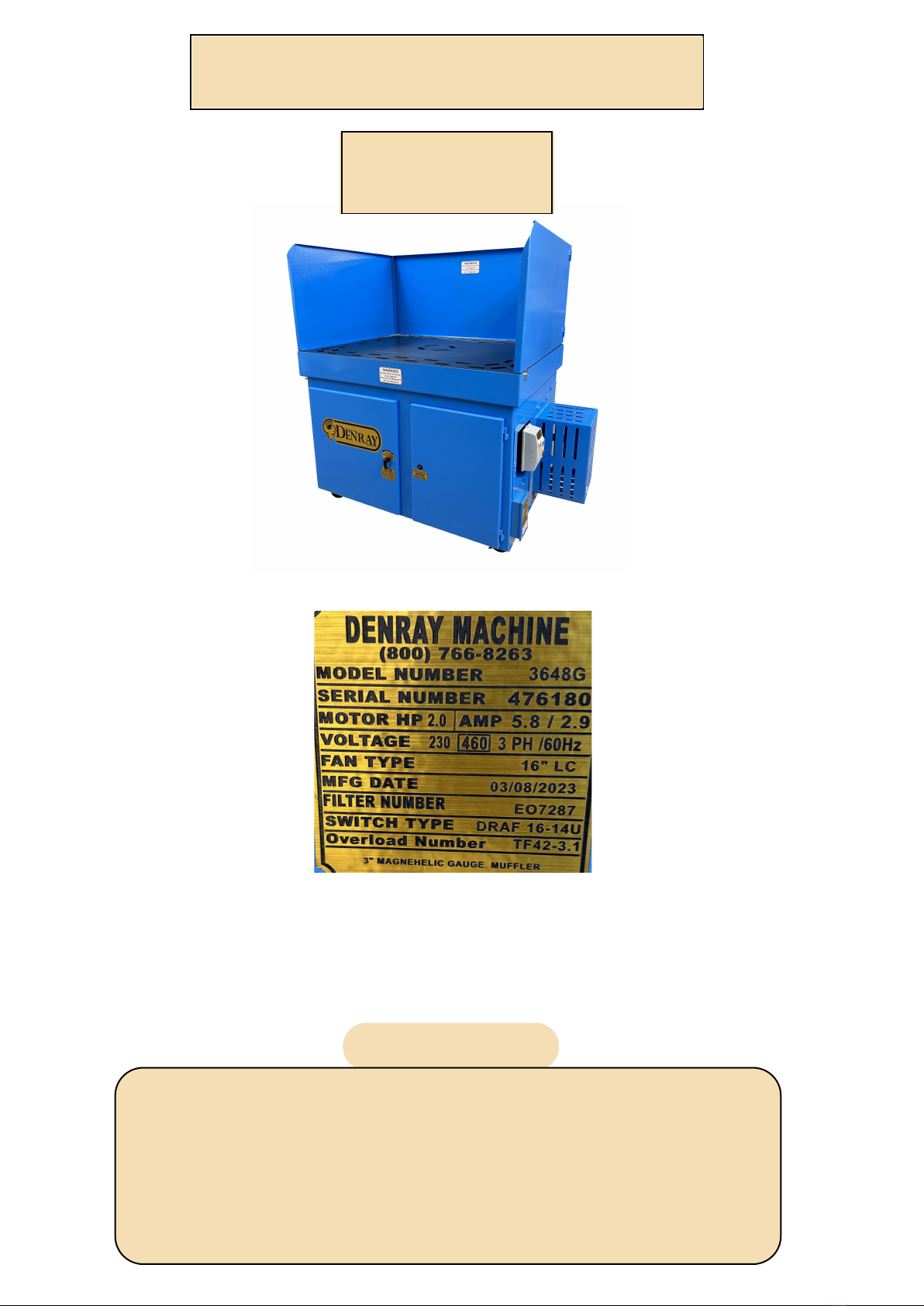
OPERATING INSTRUCTIONS
3648G
WARRANTY
This Machine is covered with a 12 month warranty. The warranty covers replacement parts, except filters
and wooden top (if applicable). The only way Denray will cover the labor is the work must be done by
Denray at Denray's Facility. The shipping must be provided by the customer (owner of the machine) both
ways. You may contact the dealer you purchased the machine from, and discuss with them, the
possibility of their assistance in helping to solve the problem in your facility. Denray assumes or accepts
no responsibility more than the cost of the machine. In the case of repair Denray will determine either to
fix or replace the product. Denray reserves the right to modify or change the design of this and any model
of their machines, without changing or updating any previous manufactured machine.
The warranty will not cover any damage done by fire or any other act of nature or if abuse or improper
maintenance was or was not performed.
To find YOUR tables pertinent information please locate the table sticker on your table.
**Please note the image above is a "generic" table sticker for visual purposes only! The table sticker
on your machine reflects how it left the manufacturer and does not reflect any after-market changes
made by previous owners. If you have questions please call Denray Machine at (800) 766-8263.
Never Allow Any Unauthorized or Untrained Person To Operate
This Machine
Lockout and tagout any time maintenance is performed on this
machine
WARNING
NEVER GRIND OR SAND ANY ALUMINUM OR MAGNESIUM, OR ANY
SPARK CREATING PRODUCT ON THIS MACHINE
Filters are the main need of maintenance, the cleaner the filters are kept the better the machine will
perform. This machine is equipped with timers to clean the filters, every so many minutes a pulse of
air will be released into one of the filters, and a few minutes later the other filter will be pulsed, the
time is needed to refill the tank. The time between pulses are adjustable, refer to the electrical
diagram. Warning if the time is reduced between pulses the filter may plug up reducing the
machines performance. The filters can also be pulsed with the machine off, it may blow dust back
into the work area, so caution should be used here, pulse the machine then turn machine on to pull
dust back into the filters.
The filters will clean better with machine off,
you may shut machine off and before it slows
down to a complete stop, pulse the filter and
allow the fan to prevent the dust from exiting
the filter compartment.
Filter replacement number is on the inside of
the filter door.Be sure to replace with same
type of filter or a filter made of polyester
media.
Cartridge Filters 99.95% efficeincy
down to .5 micron
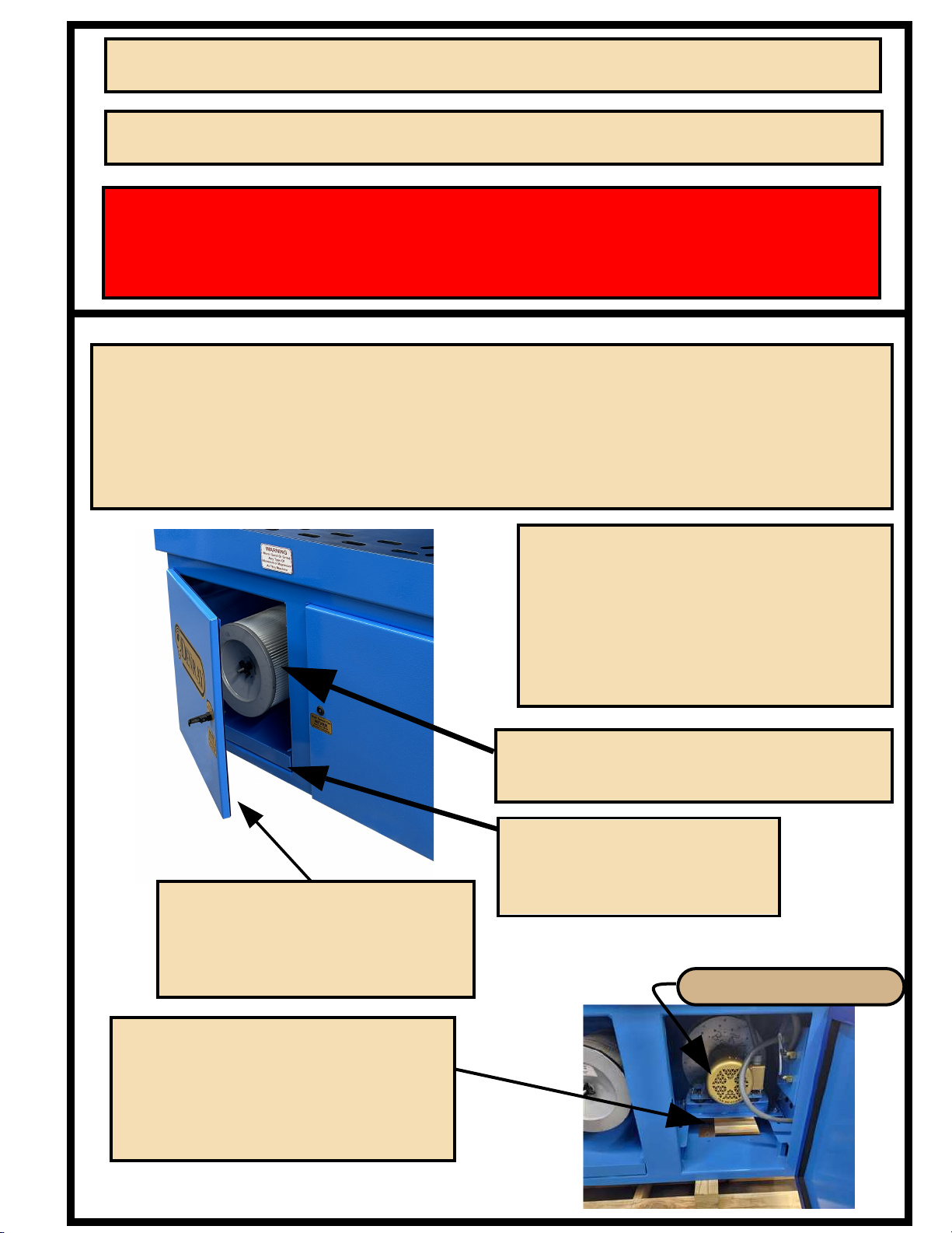
The exhaust air will exit through
opening to the floor, if muffler
is added the plate on the end will
be located here to force the air
through the muffler
Motor compartment
Dust Drawer Clean
regularly, as needed Filter replacement number
Is on inside of this door.
MUST replace with the
proper fire retardant filter
Air Tank View (Generic)
Incoming airline
90-120 psi
150 PSI Pressure relief valve, 1/4"
NPT Male, if you have air leaking
from the tank area, this is the
1st place to check.
Compression nut that holds valve
to the tank. Always apply a small
amount of either grease or oil to
the threads when reassemling to
the tank.
Never Open Any Door
While Machine Is Running
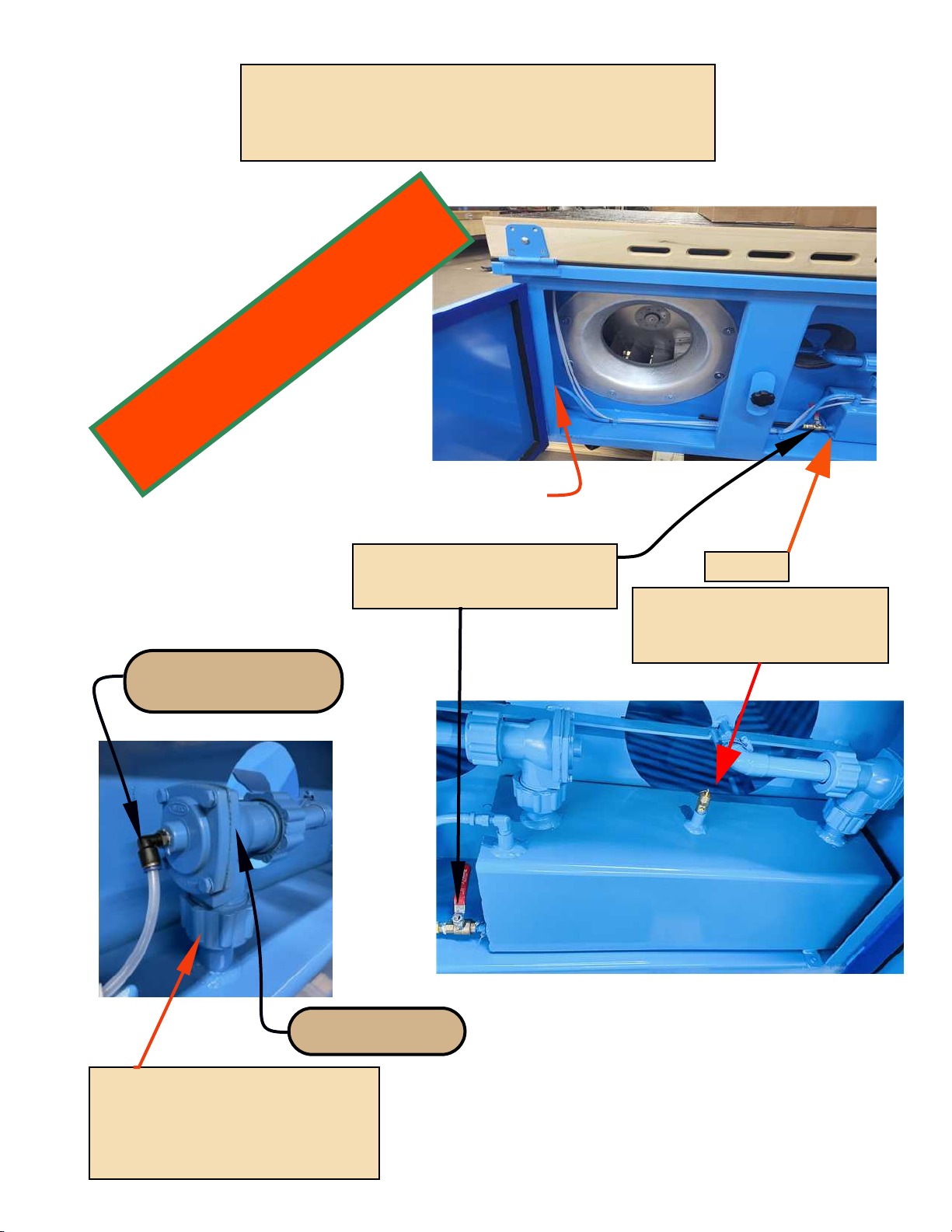
Label text
Air Tank
Drain Moisture from tank
daily, and provide clean dry
air from factory compressed air
Valve to release air into
the filters to clean them
Push on air line
if you hear a fog horn noise
check each fitting for leaks
Air Tank
to clean filters
Valves to clean Filters
Out Going Power
incoming
power
115/220 1Ph -
6
incoming power from
junction box
L 1 L 2 L 3 1 3
T 2T 1 T 3
9 7
9 8
MAN
AUT
24 1 4
MOTOR
MAG. STARTER
4
56
7
Overload dial set
just above motor
amps
TO
MOTOR
set on Auto
9 59 6
Stop button
Start Button
To Magnetic Starter
Wires Through
Hole into next Box
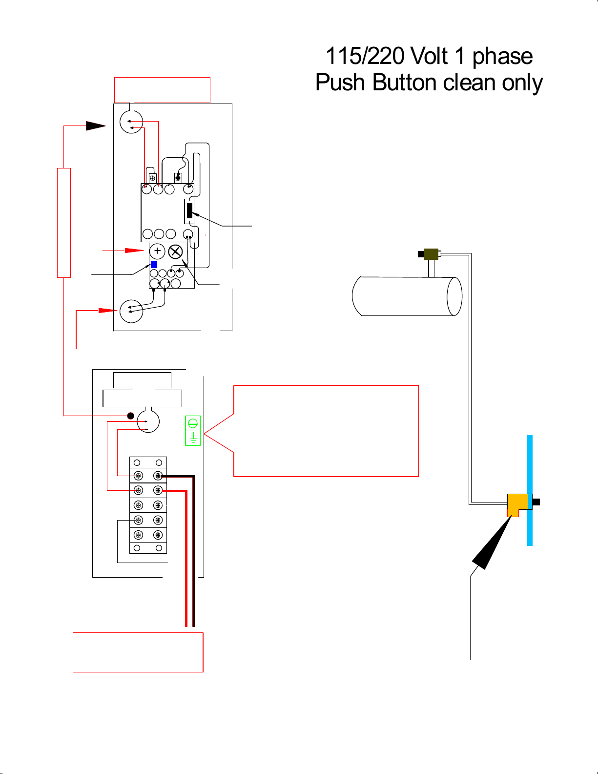
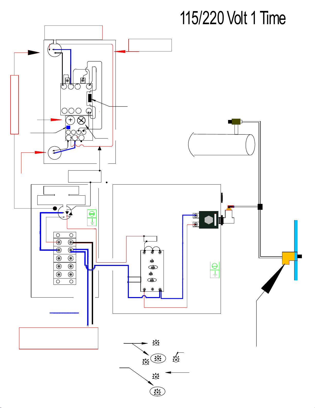
The clear Hose only carry about 5 PSI The push
button drains the air from the hose causing the
valve to pulse thus cleaning the filters. No Electrical
power needed or incoming air needed, air comes
from the air tank
115/220 Volt 1 phase
Push Button clean only
Push Button
To Clean filter/s
Box on outside
of machine for
easy wire hook up
Conduit with wire to this box
ELECTIC SOLENOID
A1 15 Y1
18 16 A2
1-10min
6-60min
1-10h
10-100h
0.1-1
1-10
6-60
1
23456789
10
Time on
1-10min
6-60min
1-10h
10-100h
0.1-1
1-10
6-60
1
2345 6 789
10
Time on
Air Tank
to clean filters
Valve to clean Filters
From T1
Out Going Power
incoming
power
115/220 Volt
6
incoming power from
junction box
L 1 L 2 L 3 1 3
T 2T 1 T 3
9 7
9 8
M A N
AUT
2 4 1 4
MOTOR
MAG. STARTER
4
56
7
Overload dial set
just above motor
amps
TO
MOTOR
set on Auto
9 59 6
Stop button
Start Button
power wire
to Transformer
To Magnetic Starter
Wires Through
Hole into next Box
Neutral
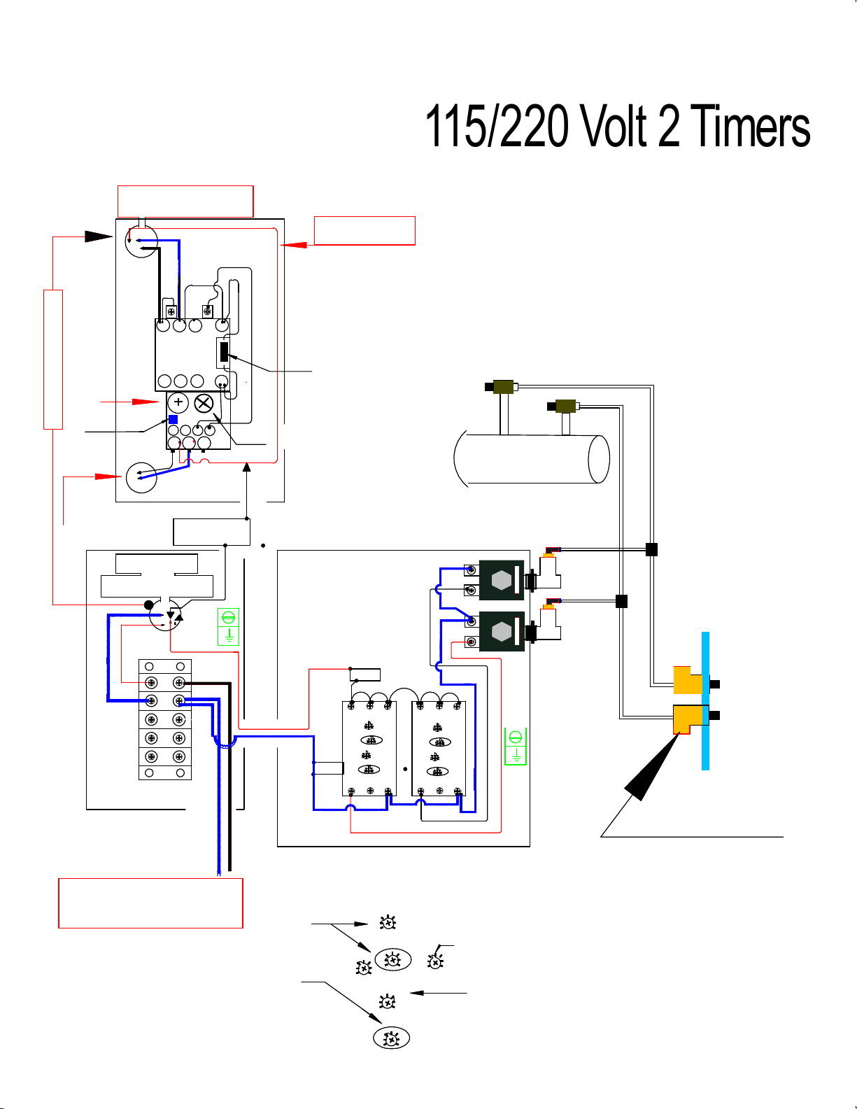
The clear Hose only carry about 5 PSI The push
button drains the air from the hose causing the
valve to pulse thus cleaning the filters. No Electrical
power needed or incoming air needed, air comes
from the air tank
Push Button
To Clean filter/s
Power
115/220 Volt 1 Timer
So The timers only
work when machine is running
Power to timers come
from T1
Conduit with wire to this box
1-10min
6-60min
1-10h
10-100h
0.1-1
1-10
6-60
1
2345 6 789
10
Time on
1-10min
6-60min
1-10h
10-100h
0.1-1
1-10
6-60
1
2345 6 789
10
Time off
Time the pulse
is on We use 2 seconds
Set on these
Set Here for 6-60min.
1=6min
2=12min
3=18min
4=24min
5=30min
6=36min
7=42min
8=48min
9=54min
10=60min
Time between
pulses
Dial with Pointer
set pointer to
proper number
6x4=24
TIMER SETTINGS
A1 15 Y1
18 16 A2
A1 15 Y1
18 16 A2
1-10min
6-60min
1-10h
10-100h
0.1-1
1-10
6-60
1
2345 6 789
10
Time on
1-10min
6-60min
1-10h
10-100h
0.1-1
1-10
6-60
1
2345 6 789
10
Time on
1-10min
6-60min
1-10h
10-100h
0.1-1
1-10
6-60
1
2345 6 789
10
Time on
1-10min
6-60min
1-10h
10-100h
0.1-1
1-10
6-60
1
2345 6 789
10
Time on
Air Tank
to clean filters
Valves to clean Filters
ELECTIC SOLENOID
ELECTIC SOLENOID
From T1
Out Going Power
incoming
power
115/220 Volt
6
incoming power from
junction box
L 1 L 2 L 3 1 3
T 2T 1 T 3
9 7
9 8
MAN
AUT
2 4 1 4
MOTOR
MAG. STARTER
4
56
7
Overload dial set
just above motor
amps
TO
MOTOR
set on Auto
9 5
9 6
Stop button
Start Button
power wire
to Transformer
To Magnetic Starter
Wires Through
Hole into next Box
Neutral
The clear Hose only carry about 5 PSI The push
button drains the air from the hose causing the
valve to pulse thus cleaning the filters. No Electrical
power needed or incoming air needed, air comes
from the air tank
Push Buttons
Power
115/220 Volt 2 Timers
So The timers only
work when machine is running
Power to timers come
from T1
Conduit with wire to this box
1-10min
6-60min
1-10h
10-100h
0.1-1
1-10
6-60
1
2345 6 789
10
Time on
1-10min
6-60min
1-10h
10-100h
0.1-1
1-10
6-60
1
2345 6 789
10
Time off
Time the pulse
is on We use 2 seconds
Set on these
Set Here for 6-60min.
1=6min
2=12min
3=18min
4=24min
5=30min
6=36min
7=42min
8=48min
9=54min
10=60min
Time between
pulses
Dial with Pointer
set pointer to
proper number
6x4=24
TIMER SETTINGS

1-10min
6-60min
1-10h
10-100h
0.1-1
1-10
6-60
1
2345 6 789
10
Time on
1-10min
6-60min
1-10h
10-100h
0.1-1
1-10
6-60
1
2345 6 789
10
Time off
Time the pulse
is on We use 2 seconds
Set on these
Set Here for 6-60min.
1=6min
2=12min
3=18min
4=24min
5=30min
6=36min
7=42min
8=48min
9=54min
10=60min
Time between
pulses
Dial with Pointer
set pointer to
proper number
6x4=24
TIMER SETTINGS
Air Tank
to clean filters
Valves to clean Filters
Out Going Power
incoming power
230 3Ph -
6
incoming power from
junction box
L 1 L 2 L 3 1 3
T 2T 1 T 3
9 7
9 8
MAN
AUT
2 4 1 4
MOTOR
MAG. STARTER
4
56
7
Overload dial set
just above motor
amps
TO
MOTOR
set on Auto
9 5
9 6
Stop button
Start Button
To Magnetic Starter
Wires Through
Hole into next Box
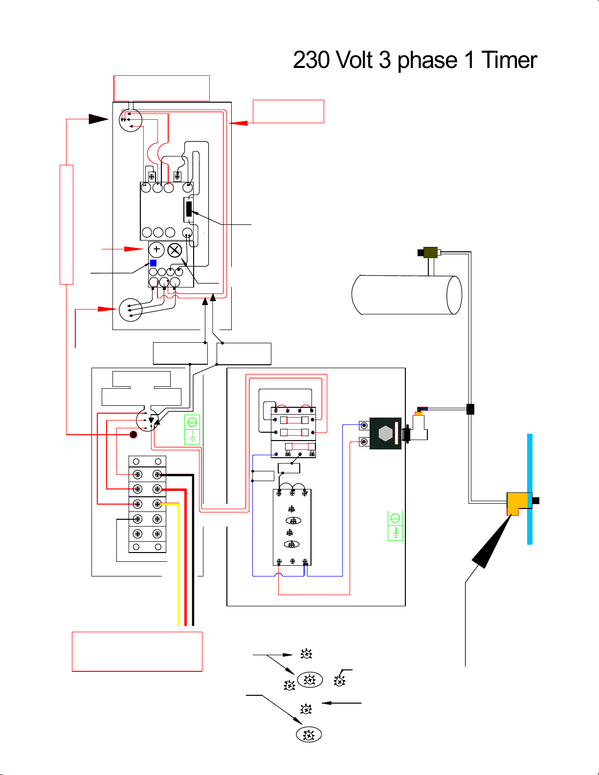
The clear Hose only carry about 5 PSI The push
button drains the air from the hose causing the
valve to pulse thus cleaning the filters. No Electrical
power needed or incoming air needed, air comes
from the air tank
230 Volt 3 phase push
Button clean only
Push Button
To Clean filter/s
Box on outside
of machine for
easy wire hook up
A1 15 Y1
18 16 A2
1-10min
6-60min
1-10h
10-100h
0.1-1
1-10
6-60
1
2345 6 789
10
Time on
1-10min
6-60min
1-10h
10-100h
0.1-1
1-10
6-60
1
2345 6 789
10
Time on
Air Tank
to clean filters
Valves to clean Filters
ELECTIC SOLENOID
230 Volt
230 Volt
Fuse 2
Fuse 1
Fuse 3
From T1
Out Going Power
incoming power
230 3Ph -
6
incoming power from
junction box
L 1 L 2 L 3 1 3
T 2T 1 T 3
9 7
9 8
MAN
AUT
24 1 4
MOTOR
MAG. STARTER
4
56
7
Overload dial set
just above motor
amps
TO
MOTOR
set on Auto
9 59 6
Stop button
Start Button
power wire
to Transformer
From T2
To Magnetic Starter
Wires Through
Hole into next Box
Neutral
The clear Hose only carry about 5 PSI The push
button drains the air from the hose causing the
valve to pulse thus cleaning the filters. No Electrical
power needed or incoming air needed, air comes
from the air tank
Power
230 Volt 3 phase 1 Timer
Push Button
To Clean filter/s
Conduit with wire to this box
1-10min
6-60min
1-10h
10-100h
0.1-1
1-10
6-60
1
2345 6 789
10
Time on
1-10min
6-60min
1-10h
10-100h
0.1-1
1-10
6-60
1
2345 6 789
10
Time off
Time the pulse
is on We use 2 seconds
Set on these
Set Here for 6-60min.
1=6min
2=12min
3=18min
4=24min
5=30min
6=36min
7=42min
8=48min
9=54min
10=60min
Time between
pulses
Dial with Pointer
set pointer to
proper number
6x4=24
TIMER SETTINGS
A1 15 Y1
18 16 A2
A1 15 Y1
18 16 A2
1-10min
6-60min
1-10h
10-100h
0.1-1
1-10
6-60
1
2345 6 789
10
Time on
1-10min
6-60min
1-10h
10-100h0.1-1
1-10
6-60
1
2345 6 789
10
Time on
1-10min
6-60min
1-10h
10-100h
0.1-1
1-10
6-60
1
2345 6 789
10
Time on
1-10min
6-60min
1-10h
10-100h
0.1-1
1-10
6-60
1
2345 6 789
10
Time on
Air Tank
to clean filters
Valves to clean Filters
ELECTIC SOLENOID
ELECTIC SOLENOID
230 Volt
230 Volt
Fuse 2
Fuse 1
Fuse 3
From T1
Out Going Power
incoming power
230 3Ph -
6
incoming power from
junction box
L 1 L 2 L 3 1 3
T 2T 1 T 3
9 7
9 8
MA N
A U T
24 1 4
MOTOR
MAG. STARTER
4
56
7
Overload dial set
just above motor
amps
TO
MOTOR
set on Auto
9 59 6
Stop button
Start Button
power wire
to Transformer
From T2
To Magnetic Starter
Wires Through
Hole into next Box
Neutral
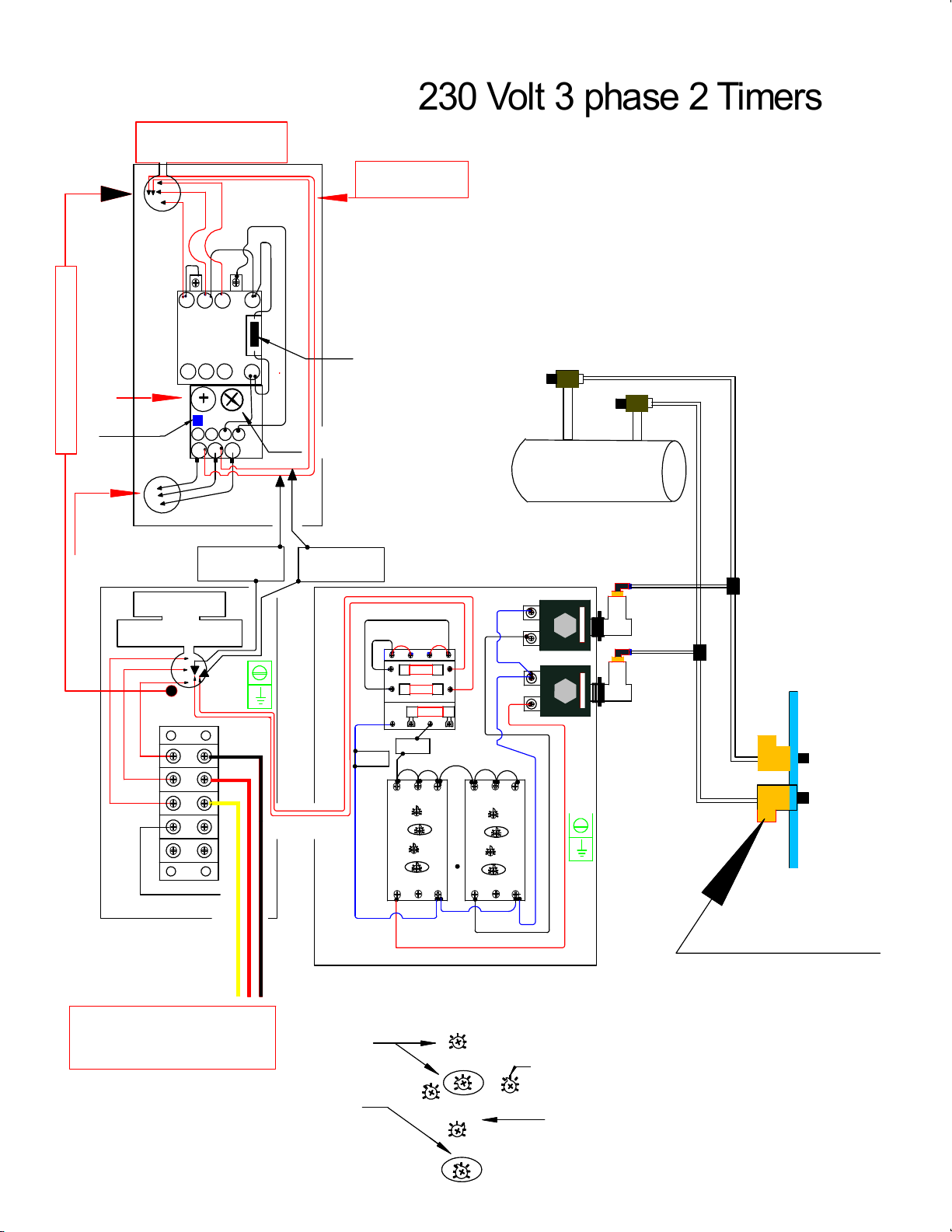
The clear Hose only carry about 5 PSI The push
button drains the air from the hose causing the
valve to pulse thus cleaning the filters. No Electrical
power needed or incoming air needed, air comes
from the air tank
Push Buttons
Power
230 Volt 3 phase 2 Timers
Conduit with wire to this box
1-10min
6-60min
1-10h
10-100h
0.1-1
1-10
6-60
1
2345 6 789
10
Time on
1-10min
6-60min
1-10h
10-100h
0.1-1
1-10
6-60
1
2345 6 789
10
Time off
Time the pulse
is on We use 2 seconds
Set on these
Set Here for 6-60min.
1=6min
2=12min
3=18min
4=24min
5=30min
6=36min
7=42min
8=48min
9=54min
10=60min
Time between
pulses
Dial with Pointer
set pointer to
proper number
6x4=24
TIMER SETTINGS
1-10min
6-60min
1-10h
10-100h
0.1-1
1-10
6-60
1
2345 6 789
10
Time on
1-10min
6-60min
1-10h
10-100h
0.1-1
1-10
6-60
1
2345 6 789
10
Time off
Time the pulse
is on We use 2 seconds
Set on these
Set Here for 6-60min.
1=6min
2=12min
3=18min
4=24min
5=30min
6=36min
7=42min
8=48min
9=54min
10=60min
Time between
pulses
Dial with Pointer
set pointer to
proper number
6x4=24
TIMER SETTINGS
Air Tank
to clean filters
Valves to clean Filters
Out Going Power
incoming power
460 3Ph -
6
incoming power from
junction box
L 1 L 2 L 3 1 3
T 2T 1 T 3
9 7
9 8
MAN
AUT
2 4 1 4
MOTOR
MAG. STARTER
4
56
7
Overload dial set
just above motor
amps
TO
MOTOR
set on Auto
9 5
9 6
Stop button
Start Button
To Magnetic Starter
Wires Through
Hole into next Box
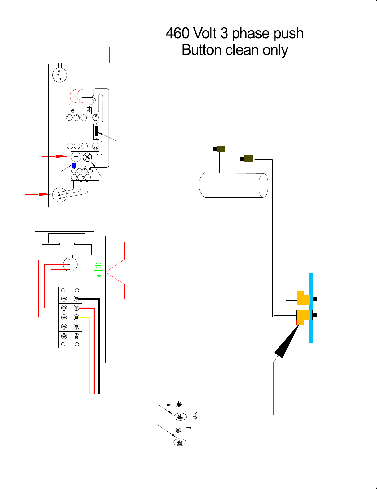
The clear Hose only carry about 5 PSI The push
button drains the air from the hose causing the
valve to pulse thus cleaning the filters. No Electrical
power needed or incoming air needed, air comes
from the air tank
460 Volt 3 phase push
Button clean only
Push Button
To Clean filter/s
Box on outside
of machine for
easy wire hook up
A1 15 Y1
18 16 A2
1-10min
6-60min
1-10h
10-100h
0.1-1
1-10
6-60
1
2345 6 789
10
Time on
1-10min
6-60min
1-10h
10-100h
0.1-1
1-10
6-60
1
2345 6 789
10
Time on
Air Tank
to clean filters
Valves to clean Filters
ELECTIC SOLENOID
Fuse 2
Fuse 1
Fuse 3
From T1
Out Going Power
incoming power
230 3Ph -
6
incoming power from
junction box
L 1 L 2 L 3 1 3
T 2T 1 T 3
9 7
9 8
MAN
AUT
24 1 4
MOTOR
MAG. STARTER
4
56
7
Overload dial set
just above motor
amps
TO
MOTOR
set on Auto
9 5
9 6
Stop button
Start Button
power wire
to Transformer
From T2
To Magnetic Starter
Wires Through
Hole into next Box
Neutral
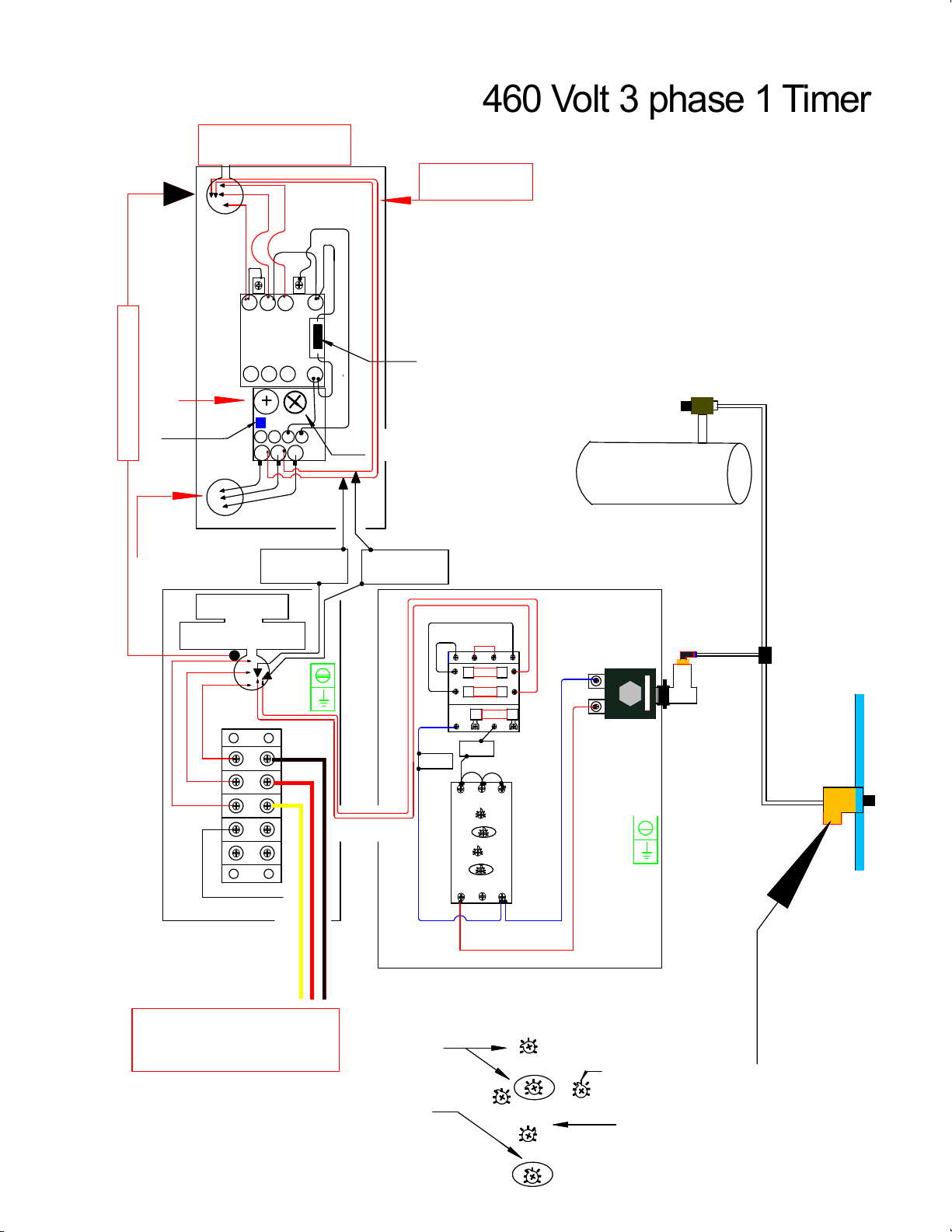
The clear Hose only carry about 5 PSI The push
button drains the air from the hose causing the
valve to pulse thus cleaning the filters. No Electrical
power needed or incoming air needed, air comes
from the air tank
Power
460 Volt 3 phase 1 Timer
Push Button
To Clean filter/s
460 Volt
Conduit with wire to this box
1-10min
6-60min
1-10h
10-100h
0.1-1
1-10
6-60
1
2345 6 789
10
Time on
1-10min
6-60min
1-10h
10-100h
0.1-1
1-10
6-60
1
2345 6 789
10
Time off
Time the pulse
is on We use 2 seconds
Set on these
Set Here for 6-60min.
1=6min
2=12min
3=18min
4=24min
5=30min
6=36min
7=42min
8=48min
9=54min
10=60min
Time between
pulses
Dial with Pointer
set pointer to
proper number
6x4=24
TIMER SETTINGS
A1 15 Y1
18 16 A2
A1 15 Y1
18 16 A2
1-10min
6-60min
1-10h
10-100h
0.1-1
1-10
6-60
1
2345 6 789
10
Time on
1-10min
6-60min
1-10h
10-100h
0.1-1
1-10
6-60
1
2345 6 789
10
Time on
1-10min
6-60min
1-10h
10-100h
0.1-1
1-10
6-60
1
2345 6 789
10
Time on
1-10min
6-60min
1-10h
10-100h
0.1-1
1-10
6-60
1
2345 6 789
10
Time on
Air Tank
to clean filters
Valves to clean Filters
ELECTIC SOLENOID
ELECTIC SOLENOID
460 Volt
Fuse 2
Fuse 1
Fuse 3
From T1
Out Going Power
incoming power
230 3Ph -
6
incoming power from
junction box
L 1 L 2 L 3 1 3
T 2T 1 T 3
9 7
9 8
MAN
AUT
24 1 4
MOTOR
MAG. STARTER
4
56
7
Overload dial set
just above motor
amps
TO
MOTOR
set on Auto
9 59 6
Stop button
Start Button
power wire
to Transformer
From T2
To Magnetic Starter
Wires Through
Hole into next Box
Neutral
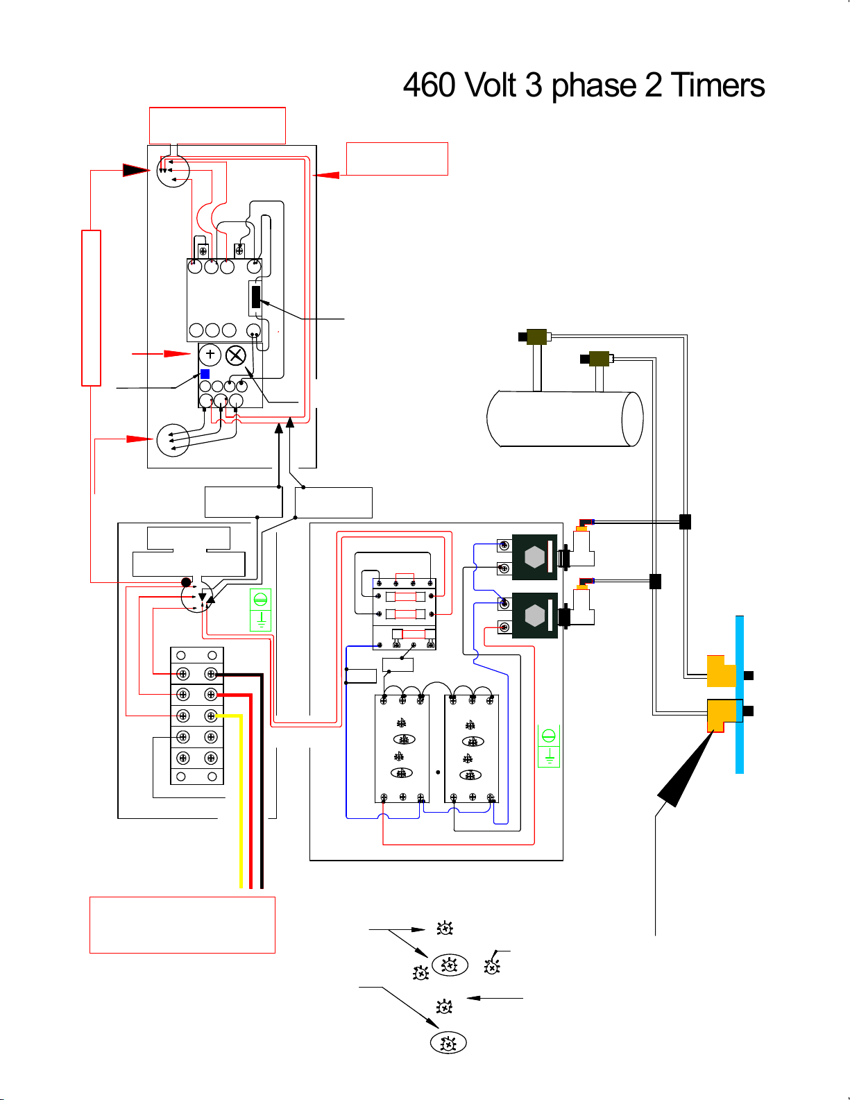
The clear Hose only carry about 5 PSI The push
button drains the air from the hose causing the
valve to pulse thus cleaning the filters. No Electrical
power needed or incoming air needed, air comes
from the air tank
Power
460 Volt 3 phase 2 Timers
Push Button
To Clean filter/s
Conduit with wire to this box
1-10min
6-60min
1-10h
10-100h
0.1-1
1-10
6-60
1
2345 6 789
10
Time on
1-10min
6-60min
1-10h
10-100h
0.1-1
1-10
6-60
1
2345 6 789
10
Time off
Time the pulse
is on We use 2 seconds
Set on these
Set Here for 6-60min.
1=6min
2=12min
3=18min
4=24min
5=30min
6=36min
7=42min
8=48min
9=54min
10=60min
Time between
pulses
Dial with Pointer
set pointer to
proper number
6x4=24
TIMER SETTINGS
TROUBLE SHOOTING
Motor not running Look to see if L1- L2 -L3
wires are in and secured
and proper voltage is there
Check if wires at bottom of
mag starter to the motor are
in bottom and secured.
The above checks OK In center of the contactor is a rectangle post that is
hooked to coil below. With screwdriver push in and see
if motor will run. If motor will run something is wrong
with the push buttons, That activates the starter.
Motor runs when center
post is held in, but not
by the switches
Make sure every wire is secured on starter if
still no results call Denray for further assistance
If center post is held in
and nothing happens
hook power leads to motor
leads at bottom of mag
starter if motor runs the
problem is the starter.
Call factory for switch replacement
If on switch closes mag
starter and motor does
not run.
FIRST take tester and check see if there is the
proper voltage at bottom of starter
If proper voltage is at
bottom of starter Check to see wiring at motor is properly
hooked together
All the below solutions are meant to be done
only by a qualified technician
Mag starter works
and motor only hums Check for proper voltage
check all wire connections to be tight
check wiring diagram and motor leads to be correct
Filter Cleaning valve will
not pulse Check the three 1 amp fuses on
top of the transformer in the
switch box.
Fuses OK Check wiring in front of and behind the fuses
Fuses and wiring checks
out OK With it being quiet activate the switch and listen
to hear a clicking sound from the valve or valves.
You hear it clicking Make sure air is hooked up to tank
Air is hooked up
and it still clicks Call Denray Replace valve
1
2
3
4
5
6
7
8
9
10
11
12
Motor runs for a
few minutes and
shuts off
Turn the amp dial on overload to increase the
number. Increase only 1 amp at a time
Never increase more than 2 amps above motor
full load amps
13

TROUBLE SHOOTING
Loss of suction on top
of table Dirty filters :: Refer to above
All the below solutions are meant to be done
only by a qualified technician
Excessive exhaust air
on the floor
Rotate filters two times a week 1/4 turn
Timer not working
Machines with timers Check fuses:: Check wiring between mag starter
and timer. Any loose connection,
secure the connection
Filters need to be
cleaned more often Turn dial on timer to a lesser number set at
factory at approx. every 20 minutes.
Lots of dirt remaining on
filters after being cleaned Decrease time between cleanings. Check air
pressure going into machine.
Keep between 100-140 psi
Filter never completely
cleans all dirt off Not supposed to:: Machine designed to operate at
30% filter blockage. The cleaner a filter is the better
the machine will perform.
Any air that is sucked into the table top must come
out in exhaust somewhere. Look into adding Muffler
to machine
Dirt packed in top 1/3 of
filters
Inside of filters are
rusty colored Blowing water from air tank inside of filter. Drain
air tank more often ( daily if possible) Installation
of a dryer or water trap may be necessary
Filters will not come
clean Pull filters out of machine and take blow gun and
from inside blowing out give filters a deep cleaning
How often do I need
to do the above Some companies do it daily and some weekly
and some monthly. You must determine that
for yourself
Moisture blowed in filters
will make filters harder
to clean
14
15
16
17
18
19
20
21
22
23
24
25
26
Refer to 22
Are filters washable? Spun-bond filters in the grind tables can be washed only
a couple times and must let thoroughly dry.
Filter cleaning service companies may be available in
your area.
Green light on timer
does not work See above
Bad timer needs replacement
All fans are factory balanced from fan company,
fans checked and rebalanced at table MFG, if
table has vibration, fan weights may need to be
moved to another blade.
TROUBLE SHOOTING
All the below solutions are meant to be done
only by a qualified technician
27
28
29
Fan making a loud roar Fan rotation backwards, on three phase,switch
wires on L1 and L2
Lack of proper suction Fan running backwards will produce 2/3rds less
suction check fan rotation
Verify Correct Fan Direction on your Machine
Machine vibration on
direct drive systems
Table of contents
Other Denray Industrial Equipment manuals


Popular Industrial Equipment manuals by other brands

EASTMAN
EASTMAN Kodak X-Omat 180 LP Service manual

KSB
KSB AmaDrainer Box Box Z2 B Installation & operating manual

Volvo
Volvo REMU user manual

Stober
Stober RB 5022 Commissioning instructions

schmersal
schmersal AZM400Z-ST-1P2P-BOW manual

Grundfos
Grundfos TPE 1000 Series Installation and operating instructions


