NI P7000 Series User manual

GETTING STARTED
NI 7330/7340/7350 Motion Controllers and
P7000 Series Stepper Drives
This manual helps you quickly install and configure the P7000 series stepper drives and stepper motors
for use with NI 7330, NI 7340, and NI 7350 motion controllers. It assumes you have already installed
your National Instruments motion controller and driver software. The driver CD installs the
NI Measurement & Automation Explorer (MAX) configuration files and documents referenced in this
manual. You can find all the software, files, and documents at ni.com/motion/stepper.
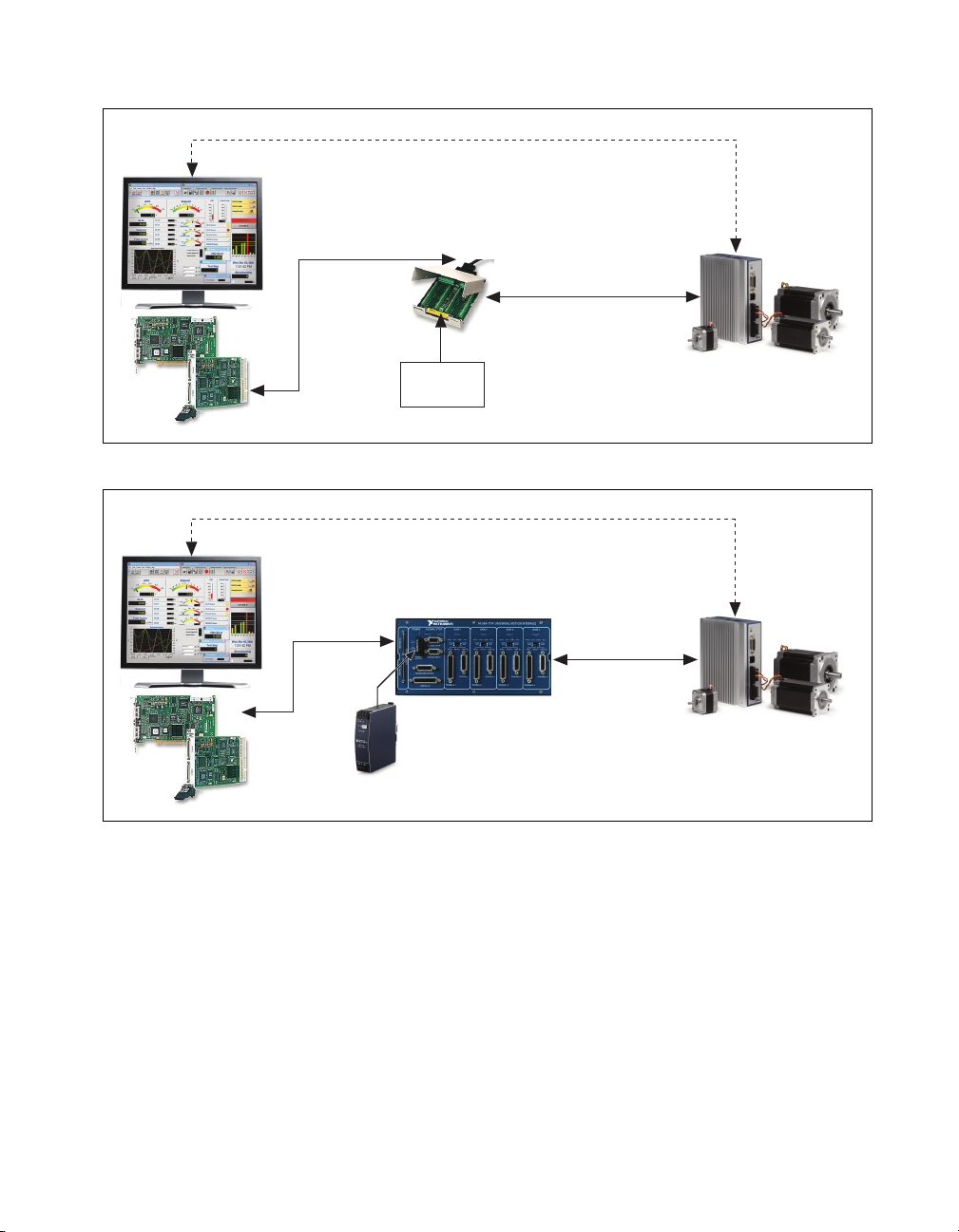
Additionally, this manual assumes you are using either the NI Universal Motion Interface (UMI)-7764
or NI UMI-7774/7772 and have the appropriate 68-pin cable for connecting to your NI motion
controller. Refer to the NI Stepper Motion System Selection Guide at ni.com/motion/stepper for
assistance. For specifications or installation questions about your NI motion controller or NI UMI, refer
to the appropriate user manual.
Contents
What You Need to Get Started ............................................................................................................ 1
Hardware...................................................................................................................................... 1
Software ....................................................................................................................................... 2
Related Documentation................................................................................................................ 3
Configuration and Installation ............................................................................................................. 4
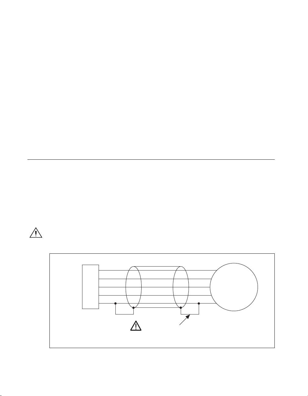
Step 1: Connecting the Stepper Motor to the Drive..................................................................... 4
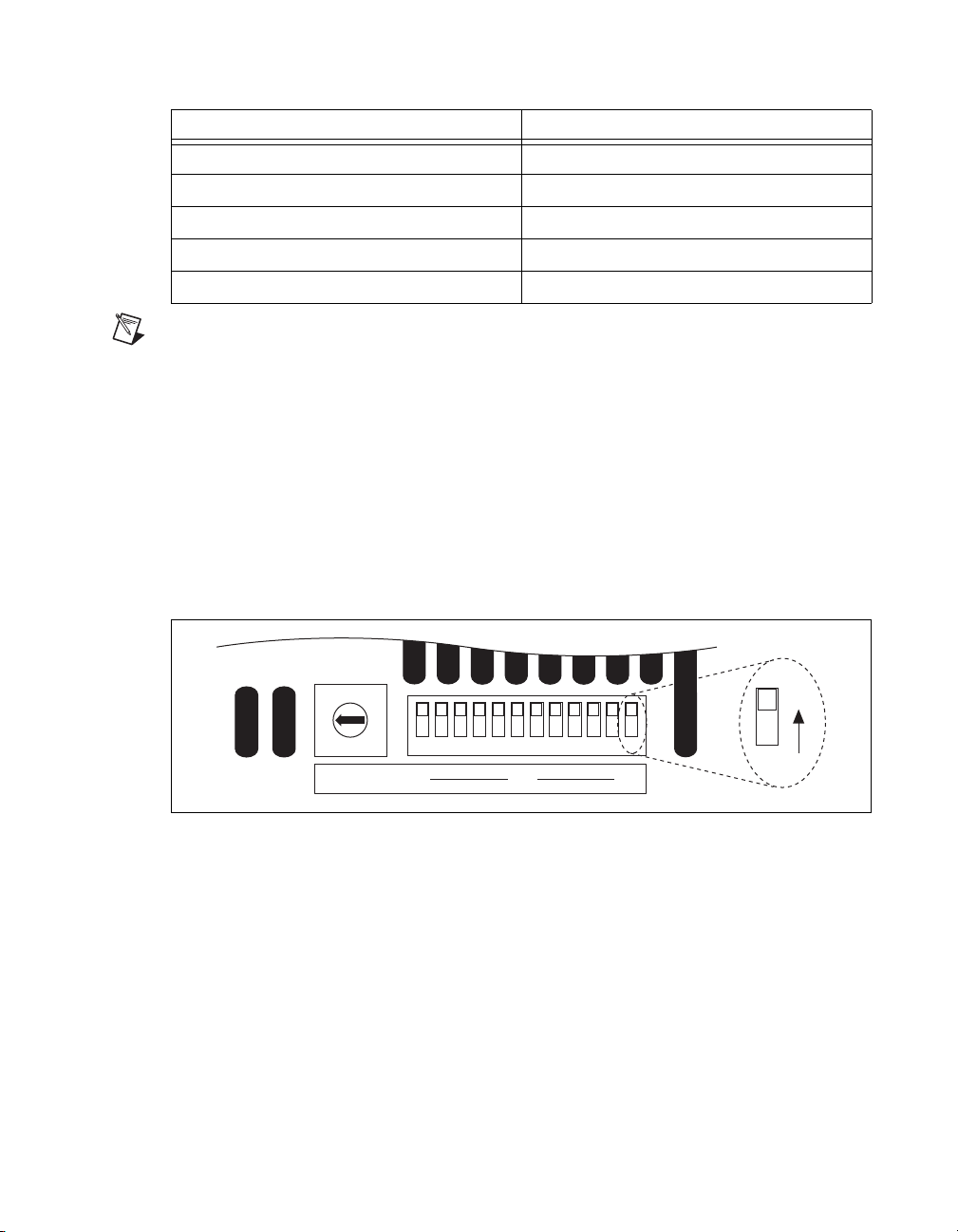
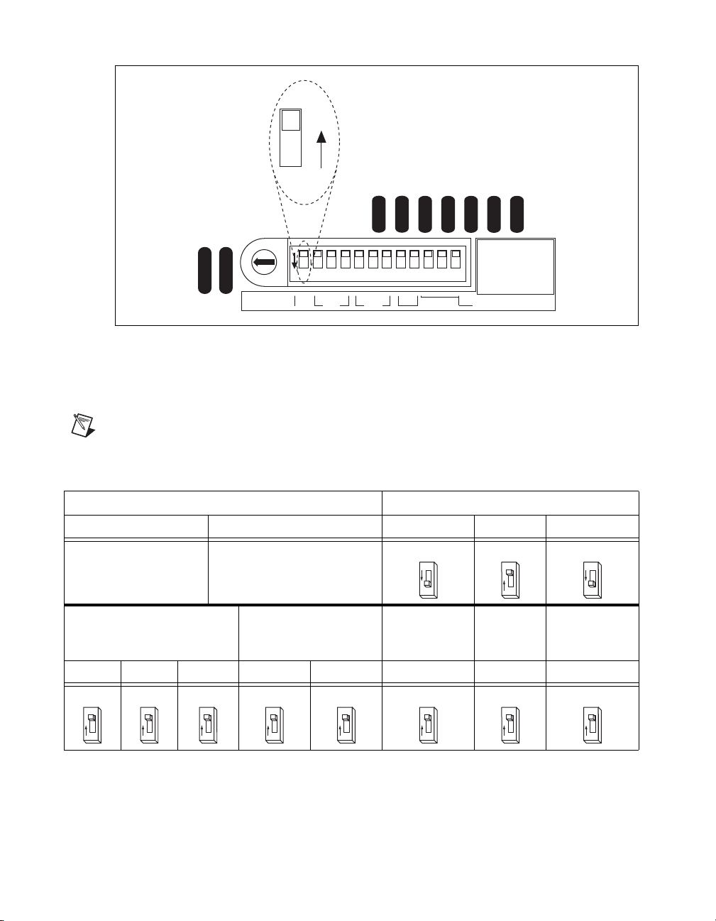
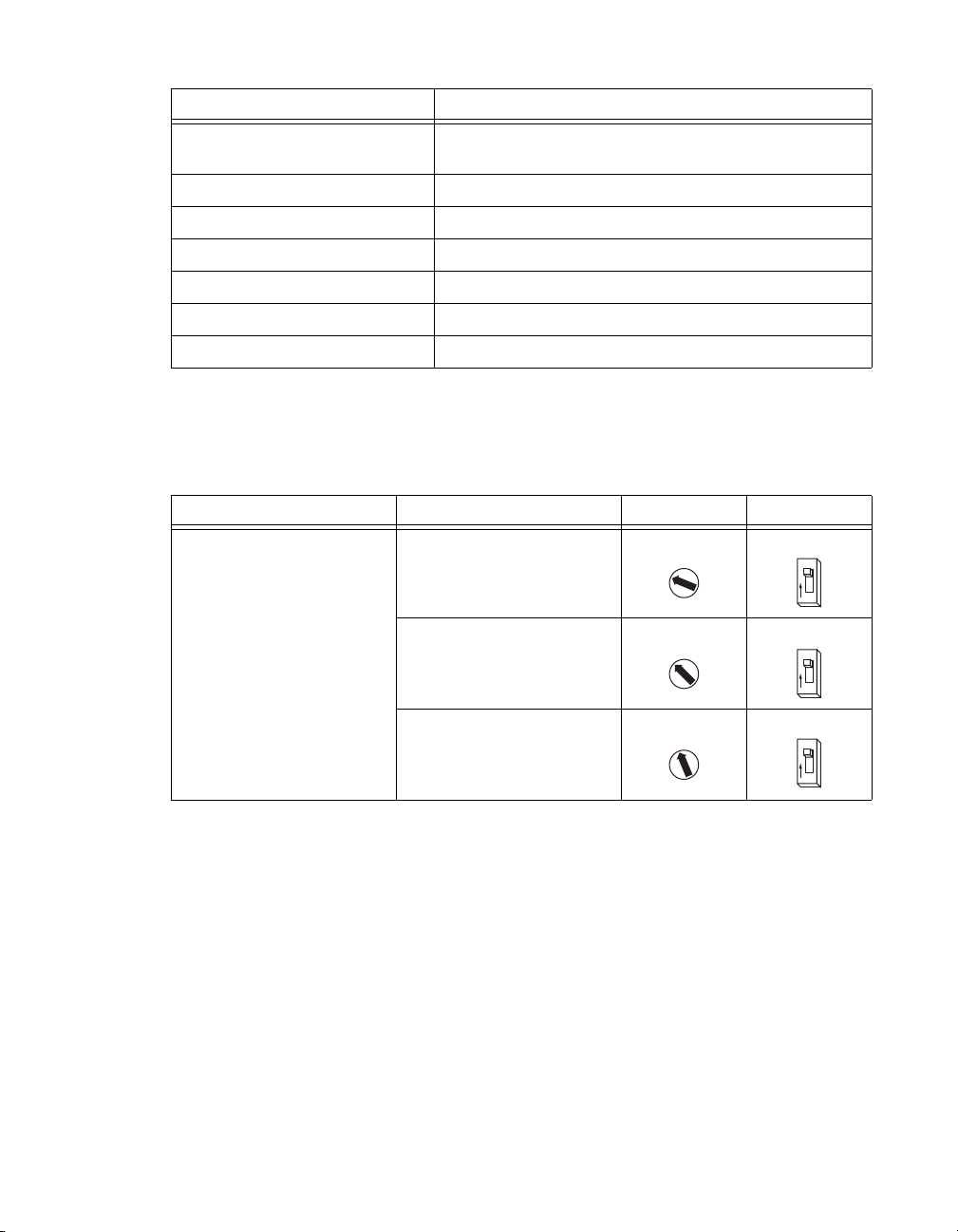
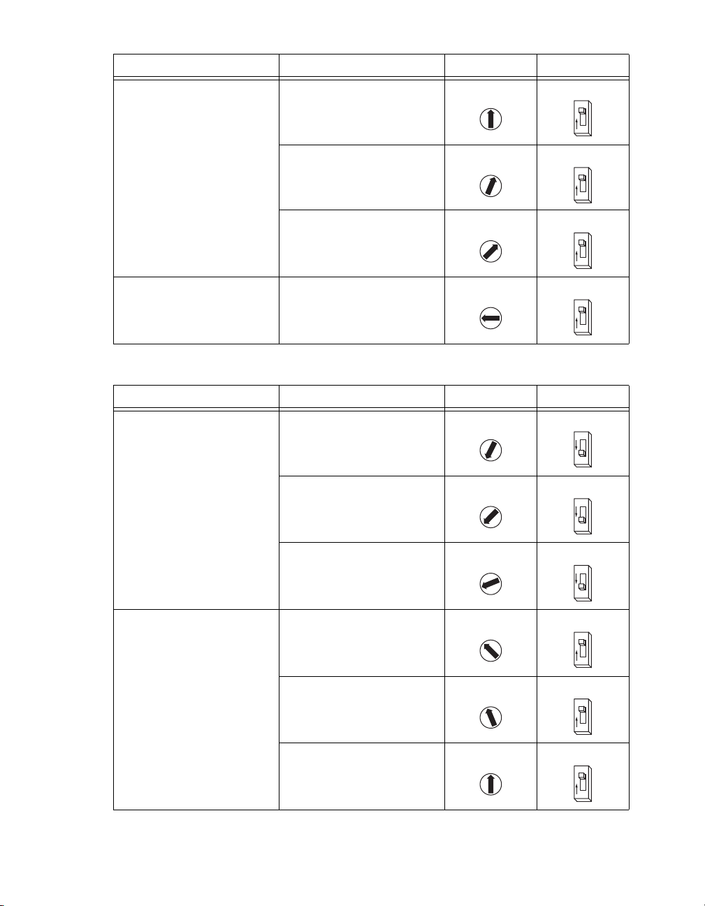
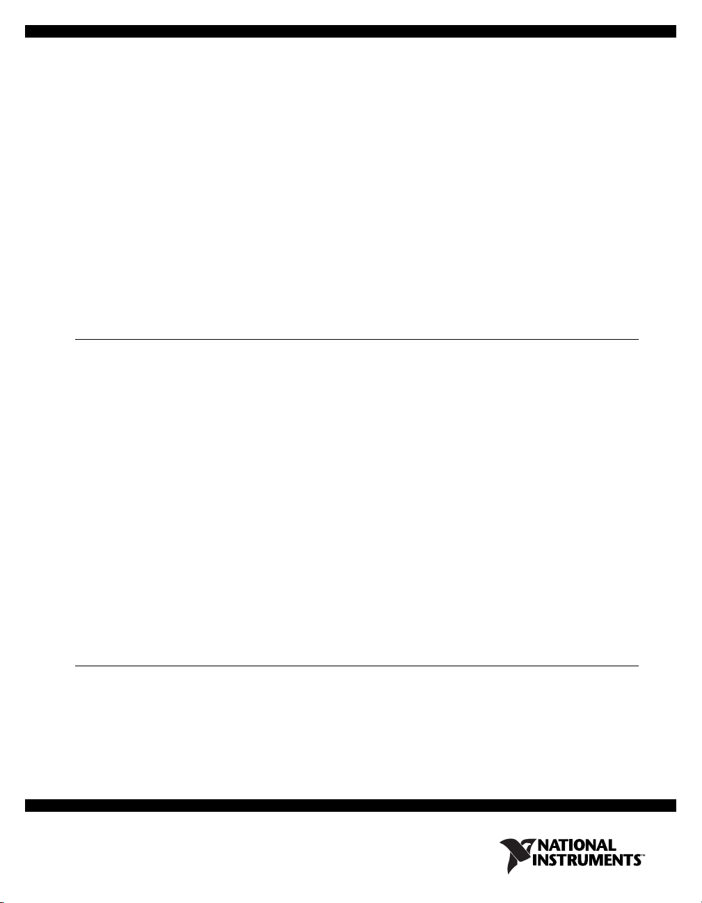
Step 2: Configuring the DIP Switches......................................................................................... 5
Step 3: Connecting Power to the P7000 Drive ............................................................................ 13
Step 4: Configuring the P7000 Drive with the Serial Port (Optional)......................................... 15
Step 5: Installing the P7000 Tools (Optional) ............................................................................. 16
Step 6: Testing the Motor With the P7000 Tools (Optional) ...................................................... 20
Step 7: Configuring the NI UMI..................................................................................................20
Step 8: Configuring Your NI Motion Controller Using Measurement & Automation
Explorer (MAX) ....................................................................................................................... 22
Step 9: Testing the Motor Using MAX ....................................................................................... 26
Configuring Moves with NI Motion Assistant (Optional)................................................................... 26
Exporting to LabVIEW................................................................................................................ 27
Troubleshooting the P7000 Series Stepper Drive................................................................................ 28
Where to Go for Support ..................................................................................................................... 28
What You Need to Get Started
You need the following items to get started.
Hardware
❑NI 7330/7340/7350 motion controller
❑NI UMI-7764 or NI UMI-7774/7772

Getting Started with NI 73xx Controllers and P7000 Drives 2ni.com
❑Power supply for the NI UMI:
– +5 V if using the UMI-7764
– +24 V if using the UMI-7774/7772
❑68-pin cable to connect your NI UMI and motion controller
❑P70360 or P70530 stepper drive
❑P7000 direct connect cable appropriate for the NI UMI you are using
❑DC power supply if using the P70530 stepper drive
❑NI or third-party stepper motor
❑NI or third-party encoder (optional)
❑RS-232 serial communication cable for P7000 drives (optional)
Software
❑NI-Motion 7.6 or later driver software
❑One of the following software packages and documentation:
– LabVIEW 7.1.1 or later
–LabWindows
™/CVI™7.0 or later
– Microsoft Visual C++ 6.0 or later
– Microsoft Visual Basic 6.0 or later
❑NI Motion Assistant 2.2 or later (optional)
❑P7000 Tools configuration software (optional)
Note The RS-232 serial configuration cable and P7000 Tools configuration software are required
only if you are using a third-party motor. If you are using an NI stepper motor, you can perform
configuration using only the DIP switches on the drive.

©National Instruments Corporation 3 Getting Started with NI 73xx Controllers and P7000 Drives
Figures 1 and 2 shows the required hardware connections when using the P7000 Series stepper drives
with the UMI-7764 and UMI-7772/74 respectively.
Figure 1. NI 73xx Motion Controller and UMI-7764 Hardware Connections to P7000 Drive
Figure 2. NI 73xx Motion Controller and UMI-7772/74 Hardware Connections to P7000 Drive
Related Documentation
The following documents contain additional information that you may find helpful. All referenced
documents ship with the product and are available at ni.com/manuals.
•NI 7330 User Manual, NI 7340 User Manual, or NI 7350 User Manual—Describes the electrical
and mechanical aspects of the NI 73xx motion controller, and contains information about installing
and operating the device.
•Getting Started with NI-Motion for NI 73xx Motion Controllers—Provides instructions for
installing and getting started with the NI-Motion driver software and NI PXI/PCI-73xx motion
controllers.
Host PC
RS-232 Cable
(Optional)
P7000 Series
Stepper Drive
(P70360 shown)
P7000
Direct Connect
Cable
SH68-C68-S
Cable
UMI-7764
+5 V Power
Supply
NI Stepper
Motors
Host PC
SHC68-C68-S
Cable
RS-232 Cable
(Optional)
+24 V Power Supply
(NI PS-15 Shown)
UMI-7772/74
P7000 Series
Stepper Drive
(P70360 shown)
P7000
Direct Connect
Cable
NI Stepper
Motors

Getting Started with NI 73xx Controllers and P7000 Drives 4ni.com
•P70360 (AC) High Performance Micro-stepping Drive Reference Guide—Provides additional
information about the electrical and mechanical aspects of the P70360 AC stepper drive, including
important safety information.
•P70530 (DC) High Performance Micro-stepping Drive Reference Guide—Provides additional
information about the electrical and mechanical aspects of the P70530 DC stepper drive, including
important safety information.
•NI-Motion Help—Contains information about selecting a motor, designing a basic move, designing
a multi-axis move, incorporating image and data acquisition into motion applications, and working
with common motion concepts, such as contouring and breakpoints. This document is task-based
and takes you through each phase of designing and executing a motion application.
•NI-Motion Function Help—Contains function reference information for C and Visual Basic and
provides details about each function, including a description of the function, a list of the function
parameters, illustrations, and error codes.
•NI-Motion VI Help—Contains LabVIEW VI reference information and provides details about each
VI, including VI descriptions, lists of VI parameters, usage, illustrations, and error codes.
•Measurement & Automation Explorer Help for Motion—Provides information about using MAX
to configure the NI 73xx motion controller as well as advanced conceptual information about topics
such as Bode analysis and control loop parameters.
Configuration and Installation
You can configure the P7000 series stepper drives using the external DIP switches or with software
through the RS-232 port. If you have an NI stepper motor, you can configure the drive and motor using
only the DIP switches. If you have a third-party motor, you must use the P7000 Tools configuration
software.
Complete the following steps to configure your stepper drive and motor:
Step 1: Connecting the Stepper Motor to the Drive
Connect the stepper motor as shown in Figure 3. The NI stepper motors are highly recommended,
as they are optimized to work with the P7000 series stepper drives.
Caution Do not hot-plug the motor connector. Also, avoid “whiskers” from stranded phase leads
protruding from the motor plug.
Figure 3. Connecting the Stepper Motor
Motor
Power
1
2
3
4
5
J6
A–
A+
B–
B+
Earth GND
Motor
To avoid electrical shock, motor
ground must be connected to
protective earth.

©National Instruments Corporation 5 Getting Started with NI 73xx Controllers and P7000 Drives
The NI stepper motor wire color code is shown in Table 1.
Note To reverse the motor rotation direction, do one of the following:
• Switch A– with A+
• Switch B– with B+
• Switch A–, A+ with B–, B+
National Instruments offers several standard stepper motors that provide optimum performance when
matched with the P7000 series stepper drive. The motors have a four flying lead configuration. If your
motor has six or eight leads, consult your distributor or the factory for assistance.
Step 2: Configuring the DIP Switches
Configure the DIP switches as follows for proper operation of your P7000 series stepper drive.
Figure 4 shows switches S2–1 through S2–12 in the OFF position for the P70360 drive.
Figure 4. DIP Switches in OFF Position for P70360 Drive
Table 1. NI Stepper Motor Wire Colors
Phase Color
A– Orange
A+ Black
B– Yel low
B+ Red
PE Green/Yellow Stripe
0
1
2
3
4
5
6
7
8
9
A
B
C
D
E
F
S1 S2
112
12345678910 11 12
12
OFF

Getting Started with NI 73xx Controllers and P7000 Drives 6ni.com
Figure 5 shows switches S2–1 through S2–12 in the OFF position for the P70530 drive.
Figure 5. DIP Switches in OFF Position for P70530 Drive
Using Table 4 or 5, set switches S1 and S2-1 to configure the drive for your motor, or use the serial
configuration using P7000 Tools if you are using a third-party motor.
For the remaining DIP switches, refer to Tables 2 and 3.
Note For DIP switch settings to take effect, you must power cycle the P7000 series stepper drive
whenever you make changes.
Table 2. DIP Switch Positions
Motor Selection Step Resolution
S1 S2–1 S2–2 S2–3 S2–4
Motor Dependent Motor Dependent ON OFF ON
Load Inertia Dynamic Smoothing
Current
Reduction
Multi-
stepping
Encoderless
Stall
Detection
S2–5 S2–6 S2–7 S2–8 S2–9 S2–10 S2–11 S2–12
OFF OFF OFF OFF OFF OFF OFF OFF
0
1
2
3
4
5
6
7
8
9
A
B
C
D
E
F
1234567891011 12
1
OFF
ON
S1 Motor S2 24578910-12
Step Load Smooth Advanced
Computer Setup
S1=0,
S2 1-12 = OFF
High = OFF, Open
Low = ON, Closed
2
O
N3
O
F
F
4
O
N
5
O
F
F
6
O
F
F
7
O
F
F
8
O
F
F
9
O
F
F
10
O
F
F
11
O
F
F
12
O
F
F

©National Instruments Corporation 7 Getting Started with NI 73xx Controllers and P7000 Drives
Motor Selection
Table 4 lists the switch settings for AC P70360-compatible motors. Table 5 lists the switch settings for
DC P70530-compatible motors.
Table 3. Drive Settings
Drive Option Setting
Motor selection Motor dependent (refer to Tables 4 and 5 for
switch positions)
Step resolution 5,000 (refer to Table 6 for switch positions)
Load inertia 0–1 (refer to Table 7 for switch positions)
Dynamic smoothing Minimal (refer to Table 8 for switch positions)
Current reduction Enabled (refer to Table 9 for switch positions)
Multistepping Disabled (refer to Table 10 for switch positions)
Encoderless stall detection Disabled (refer to Table 11 for switch positions)
Table 4. P70360-Compatible Motor DIP Switch Settings
Motor Frame Motor S1 S2–1
NI NEMA 23 T21NRLC 1OFF
T22NRLC 2OFF
T23NRLC 3OFF
0
1
2
3
4
5
6
7
8
9
A
B
C
D
E
F
1
O
F
F
0
1
2
3
4
5
6
7
8
9
A
B
C
D
E
F
1
O
F
F
0
1
2
3
4
5
6
7
8
9
A
B
C
D
E
F
1
O
F
F

Getting Started with NI 73xx Controllers and P7000 Drives 8ni.com
NI NEMA 34 N31HRLG 4OFF
N32HRLG 5OFF
N33HRLG 6OFF
Third-party Serial configuration using
P7000 Tools
0OFF
Table 5. P70530-Compatible Motor DIP Switch Settings
Motor Frame Motor S1 S2–1
NI NEMA 17 CTP 10 ELF 10 DON
CTP 11 ELF 11 EON
CTP 12 ELF 10 FON
NI NEMA 23 T21NRLH 2OFF
T22NRLG 3OFF
T23NRLH 4OFF
Table 4. P70360-Compatible Motor DIP Switch Settings (Continued)
Motor Frame Motor S1 S2–1
0
1
2
3
4
5
6
7
8
9
A
B
C
D
E
F
1
O
F
F
0
1
2
3
4
5
6
7
8
9
A
B
C
D
E
F
1
O
F
F
0
1
2
3
4
5
6
7
8
9
A
B
C
D
E
F
1
O
F
F
0
1
2
3
4
5
6
7
8
9
A
B
C
D
E
F
1
O
F
F
0
1
2
3
4
5
6
7
8
9
A
B
C
D
E
F
1
O
N
0
1
2
3
4
5
6
7
8
9
A
B
C
D
E
F
1
O
N
0
1
2
3
4
5
6
7
8
9
A
B
C
D
E
F
1
O
N
0
1
2
3
4
5
6
7
8
9
A
B
C
D
E
F
1
O
F
F
0
1
2
3
4
5
6
7
8
9
A
B
C
D
E
F
1
O
F
F
0
1
2
3
4
5
6
7
8
9
A
B
C
D
E
F
1
O
F
F

©National Instruments Corporation 9 Getting Started with NI 73xx Controllers and P7000 Drives
Step Resolution
Table 6 lists the step resolution switch settings.
NI NEMA 34 N31HRHJ 1ON
N32HRHJ 2ON
N33HRHJ 3ON
Third-party Serial configuration using
P7000 Tools
0OFF
Table 6. Step Resolution DIP Switch Settings
Resolution S2–2 S2–3 S2–4
200
(Full Step)
ON ON ON
400
(Half Step)
OFF ON ON
5,000 ON OFF ON
10,000 OFF OFF ON
18,000 ON ON OFF
Table 5. P70530-Compatible Motor DIP Switch Settings (Continued)
Motor Frame Motor S1 S2–1
0
1
2
3
4
5
6
7
8
9
A
B
C
D
E
F
1
O
N
0
1
2
3
4
5
6
7
8
9
A
B
C
D
E
F
1
O
N
0
1
2
3
4
5
6
7
8
9
A
B
C
D
E
F
1
O
N
0
1
2
3
4
5
6
7
8
9
A
B
C
D
E
F
1
O
F
F
2
O
N
3
O
N
4
O
N
2
O
F
F
3
O
N
4
O
N
2
O
N
3
O
F
F
4
O
N
2
O
F
F
3
O
F
F
4
O
N
2
O
N
3
O
N
4
O
F
F

Getting Started with NI 73xx Controllers and P7000 Drives 10 ni.com
Load Inertia
The P7000 series stepper drives eliminate the resonance typical of step motors with high-speed, digital
processing of motor electrical activity. To use this feature, you must set three switches based on the
load-to-rotor inertia ratio. These switches select the gain parameter the drive uses to stabilize the motor.
You can calculate the load inertia by hand or by using the Motioneering sizing software. If you do not
know your inertia ratio, set the DIP switches to OFF for a load-to-rotor inertia ratio of 0–1.
Table 7 lists the load inertia switch settings.
25,000 OFF OFF OFF
25,400 OFF ON OFF
50,000 ON OFF OFF
Table 7. Load Inertia DIP Switch Settings
Load-to-Rotor
Inertia Ratio S2–5 S2–6 S2–7
0–1 OFF OFF OFF
1–1.5 ON OFF OFF
1.5–2.5 OFF ON OFF
2.5–5.0 ON ON OFF
5.0–7.0 OFF OFF ON
Table 6. Step Resolution DIP Switch Settings (Continued)
Resolution S2–2 S2–3 S2–4
2
O
F
F
3
O
F
F
4
O
F
F
2
O
F
F
3
O
N
4
O
F
F
2
O
N
3
O
F
F
4
O
F
F
5
O
F
F
6
O
F
F
7
O
F
F
5
O
N
6
O
F
F
7
O
F
F
5
O
F
F
6
O
N
7
O
F
F
5
O
N
6
O
N
7
O
F
F
5
O
F
F
6
O
F
F
7
O
N

©National Instruments Corporation 11 Getting Started with NI 73xx Controllers and P7000 Drives
Dynamic Smoothing
Dynamic smoothing is a temporal filter (second-order, low-pass) applied to the command sequence to
reduce jerk. It helps reduce overshoot and lessens the excitation of mechanical resonance in the system.
It filters from slightly below the resonant frequency up to well above resonance to remove spectral
content that would be misrepresented in the motor output and may also excite other parts of the machine.
Dynamic smoothing is a very powerful feature for achieving maximum torque from the motor. However,
it is difficult to optimize and is not necessary for the vast majority of applications. Therefore, National
Instruments recommends setting both DIP switches to OFF for minimal smoothing.
Table 8 lists the dynamic smoothing switch settings.
7.0–12.0 ON OFF ON
12.0–20.0 OFF ON ON
20.0–32.0 ON ON ON
Table 8. Dynamic Smoothing DIP Switch Settings
Dynamic Smoothing S2–8 S2–9
Minimal OFF OFF
Moderate ON OFF
Heavy OFF ON
Aggressive ON ON
Table 7. Load Inertia DIP Switch Settings (Continued)
Load-to-Rotor
Inertia Ratio S2–5 S2–6 S2–7
5
O
N
6
O
F
F
7
O
N
5
O
F
F
6
O
N
7
O
N
5
O
N
6
O
N
7
O
N
8
O
F
F
9
O
F
F
8
O
N
9
O
F
F
8
O
F
F
9
O
N
8
O
N
9
O
N

Getting Started with NI 73xx Controllers and P7000 Drives 12 ni.com
Current Reduction
Current reduction reduces drive and motor heating by invoking standby current reduction. When
enabled, current reduction cuts motor current to 75 percent of its commanded value 100 ms after receipt
of the last step pulse. You can adjust the reduction proportion and delay to other values using the P7000
Tools configuration software.
When current reduction is enabled, the motor holding torque is reduced. Do not enable it for applications
that require full holding torque when the motor is stationary.
Table 9 lists the current reduction DIP switch settings.
Note Current reduction is enabled when switch S2–10 is OFF.
Multistepping
Multistepping is similar to dynamic smoothing, except it is a much more aggressive use of the filter.
Typically, it results in a filter that begins to roll off two octaves below the resonant frequency. This
is intended for use with coarse resolution (full/half-step input pulses) to smooth large steps into a
continuous train of microsteps, and may provide smoother motion depending on your motion
application. Disable multistepping if you are not using full or half step resolution.
Table 10 lists the multistepping switch settings.
Table 9. Current Reduction DIP Switch Settings
Current Reduction S2–10
Enabled OFF
Disabled ON
Table 10. Multistepping DIP Switch Settings
Multistepping S2–11
Enabled ON
Disabled OFF
10
O
F
F
10
O
N
11
O
N
11
O
F
F

©National Instruments Corporation 13 Getting Started with NI 73xx Controllers and P7000 Drives
Encoderless Stall Detection
The P7000 series stepper drive is uniquely designed to sense the motor shaft position at all times. The
drive monitors the commanded position and compares it to the actual position. As with any two-phase
step motor, when the shaft position and commanded position are greater than two full steps apart, a stall
is detected, and the drive faults.
Table 11 lists the encoderless stall detection switch settings.
Encoderless stall detection uses an internal motor model for stall detection. Motors listed in Tables 4
and 5 work well with encoderless stall detection. Third-party motors may not work as well, as the
algorithm is subject to constraints. National Instruments makes no guarantees of reliability of this
feature when using third-party motors.
Step 3: Connecting Power to the P7000 Drive
Connect either AC or DC input power to your P7000 series stepper drive. If you are using the P70360
drive, connect AC power as shown in Figure 6. Refer to Table 12 for DC power connector pin
descriptions. If you are using the P70530 drive, connect DC power as shown in Figure 7. Refer to
Table 13 for DC power connector pin descriptions.
Connecting AC Power to the P70360
Caution Do not use J7 as an on/off switch. Hot plugging damages the connector.
Table 11. Encoderless Stall Detection DIP Switch Settings
Encoderless Stall Detection S2–12
Enabled ON
Disabled OFF
Table 12. J7 AC Power for 320 VDC Bus
Pin Description
J7–1 120/230 VAC line
J7–2 230 VAC neutral
J7–3 120 VAC neutral
J7–4 PE (Protective Earth)
12
O
N
12
O
F
F

Getting Started with NI 73xx Controllers and P7000 Drives 14 ni.com
Figure 6. 320 VDC Bus Connection
Refer to the P70360 (AC) High Performance Micro-stepping Drive Reference Guide, available from
ni.com/manuals or from the Product Support Package CD in your kit, for 160 VDC bus connection.
This configuration is required for third-party motors with 7 to 30 mH inductance.
Connecting DC Power
Figure 7. DC Power Connector
Note National Instruments recommends using insulated wire ferrules to prevent shorting and add
strain relief.
Table 13. J7 DC Power
Pin Description
J7–1 (+Bus) Plus power supply terminal 20 to 75 V
5 A max
Isolated, unregulated (or regulated)
power supply
J7–2
(Gnd)
Negative power supply terminal
Negative power supply terminal/Bus
Gnd is normally earthed
Maximum allowable voltage between
Bus Gnd (J7–2) and Chassis (J7–3) is
100 V peak
J7–3
(PE)
Connect to PE (Protective Earth)
J7–3 connects to J6–5 inside drive (shield)
J7 Line
120N
~
120
1
2
3
4
J7 Line
240N
~
240
Connection for a 320 VDC Bus
Using 240 VAC
Connection for a 320 VDC Bus
Using 120 VAC
AC
Power
Connecting
240 VAC to pin 3 of
AC power connector
damages the drive.
AC
Power PE (Protective Earth)
PE (Protective Earth)
1
2
3
4
+Bus Gnd PE
J7 DC Power

©National Instruments Corporation 15 Getting Started with NI 73xx Controllers and P7000 Drives
Power on your DC or AC power supply. Once powered, the P7000 drive enters a configuration mode
that causes the LED to flash and the motor to audibly squeal. This is expected operation, as the drive
is measuring the motor windings to optimize its settings. Once complete, the status LED should
illuminate green. If it is not, refer to the Troubleshooting the P7000 Series Stepper Drive section.
Note The following step is required only if you are using the P7000 Tools configuration software
and configuring the drive with the RS-232 port. If you are using an NI stepper motor, you can
configure the drive with the DIP switches only and proceed to Step 7: Configuring the NI UMI
to configure the NI UMI.
Step 4: Configuring the P7000 Drive with the Serial Port (Optional)
1. Connect the RS-232 serial communication cable between the drive and computer COM1 port.
You must set the COM1 port to the following settings:
• Baud Rate: 19,200
• Data Bits: 8
• Parity: Even
•StopBits: 1
• Flow Control: None
2. Configure a COM port to be used with the serial cable. To change your COM port, open the Device
Manager, click Ports (COM & LPT), and double-click the desired COM port as shown in
Figure 8.
Figure 8. Selecting the COM1 Port in the Device Manager

Getting Started with NI 73xx Controllers and P7000 Drives 16 ni.com
3. Select the Port Settings tab and change the settings as shown in Figure 9. Click OK to apply the
new settings. Close the Device Manager after this step.
Figure 9. COM Port Settings
Step 5: Installing the P7000 Tools (Optional)
1. Install the P7000 Tools configuration software. You can find the software at ni.com/motion/
stepper.
Note If you have a previous version of P7000 Tools on your system, the installation wizard
automatically uninstalls it. After the previous version is uninstalled, you must run the installer again
to install the new version.

Getting Started with NI 73xx Controllers and P7000 Drives 18 ni.com
3. Click Next, and the P7000 software searches for connected drives on the COM1 port. Once
detected, the product selection dialog appears as shown in Figure 11. You may enter a new name
for the drive or leave the default.
Figure 11. Product Selection
4. Click Next.

©National Instruments Corporation 19 Getting Started with NI 73xx Controllers and P7000 Drives
5. In the motor selection dialog, shown in Figure 12, select the NI stepper motor you have connected
to the drive. If you are using a third-party motor, select None from the list, click the Motor File
Editor button, and enter the motor information. The T23NRLC motor is selected in this example.
Figure 12. Motor Selection
6. Click Next.
7. Click Next in the mechanical information, command values, and I/O functions dialog boxes.
No changes are required for these settings.
8. Click Finish. Your drive setup is complete.
The P7000 Tools configuration software downloads the new configuration data to your drive and
performs an initialization process with the motor. You may see a dialog box such as the one in
shown Figure 13 when the configuration data is about to download. Click Yes to continue the
download process.
Figure 13. Motor Type Conflict

Getting Started with NI 73xx Controllers and P7000 Drives 20 ni.com
9. When the configuration data is downloaded, the drive performs the initialization process with the
motor as shown in Figure 14. Click OK.
Figure 14. Drive and Motor Initialization
Caution The motor shaft rotates when performing the following test.
Step 6: Testing the Motor With the P7000 Tools (Optional)
Test the motor and P7000 series stepper drive configuration by jogging the motor in the negative and
positive directions using the following arrows on the Motion Toolbar.
Note The RS-232 serial communication cable between the computer and P7000 series stepper drive
is no longer needed, but you can leave it connected.
Step 7: Configuring the NI UMI
Follow these steps to connect and configure your NI UMI. (Refer to Figure 1 for more information about
connecting the NI UMI to your stepper drive.)
1. Connect your 68-pin shielded cable between the Motion I/O connector on your NI motion
controller and the Motion I/O connector on your NI UMI.
2. Connect the P7000 direct connect cable between the NI UMI and the P7000 series stepper drive.
If you are using the NI UMI-7774/7772, connect the cable between the Control connector on the
NI UMI and the Command I/O connector on the drive. If you are using the NI UMI-7764, connect
the leads from the cable to the correct screw terminal. The leads are labeled with the same signal
Icon Behavior Description
Jog motor negative Jogs the motor in the negative direction
at the selected velocity.
Jog velocity toggle Selects the active jog velocity for the jog
arrow buttons.
(L designates low speed;
H designates high speed.)
Jog motor positive Jogs the motor in the positive direction at
the selected velocity.
Stop motion Stops all motion.
This manual suits for next models
8
Table of contents
Other NI DC Drive manuals
Popular DC Drive manuals by other brands

TECO-Westinghouse
TECO-Westinghouse F510 Series user manual

SOMFY
SOMFY Sonesse ULTRA 30 WireFree RTS Li-ion Quick programming guide

Pfeiffer Vacuum
Pfeiffer Vacuum TC 1200 EC operating instructions

IBM
IBM ThinkPad 73P3279 user guide

MAIMAN ELECTRONICS
MAIMAN ELECTRONICS SF6100 user manual

YASKAWA
YASKAWA GA700 GA700 Series manual