NI VRTS User manual

GETTING STARTED GUIDE
VRTS with 1 GHz Bandwidth
This document describes the proper slot placement and module connections needed for the
Vehicle Radar Test System (VRTS) with 1 GHz Bandwidth. The VRTS provides automated
radar measurement and obstacle simulation capabilities for 76 GHz to 81 GHz vehicular radar
systems.
Caution The protection provided by this product may be impaired if it is used in a
manner not described in this document.
VRTS Configuration Options and Equipment
NI provides several configuration options for the VRTS hardware. These setups incorporate
either a monostatic or bistatic base configuration and can detect between one and four obstacles.
Refer to the VRTS Ordering Guide for information about your system configuration and
equipment.
Equipment
All configurations require a combination of the following hardware:
• NI-5692 Variable Delay Generator (VDG)
• PXIe-5840 Vector Signal Transceiver (VST)
• NI PXI Express controller
• NI PXI Express chassis:
– NI PXI Express chassis with 9 PXI Express or Hybrid slots (supports up to two
obstacles)
– NI PXI Express chassis with 18 PXI Express or Hybrid slots (supports up to four
obstacles)
• One of the following:
– mmRH-3608 76-81 GHz Transceiver mmWave Radio Head, Mono-Static
– mmRH-3608 76-81 GHz Transceiver mmWave Radio Head, Bi-Static
• Cables included in your product bundle

2|ni.com |VRTS with 1 GHz Bandwidth Getting Started Guide
Preparing the Environment
Ensure that the environment you are using the VRTS in meets the following specifications.
Note Refer to the VRTS with 1 GHz Bandwidth Specifications for complete
specifications.
Maximum altitude.............................................2,000 m (800 mbar)
(at 25 °C ambient temperature)
Measurement category ...................................... I
Note Measurement Categories CAT I and CAT O (Other) are equivalent. These test
and measurement circuits are not intended for direct connection to the MAINs
building installations of Measurement Categories CAT II, CAT III, or CAT IV.
Pollution degree ................................................2
For indoor use only.
Operating Environment
Ambient temperature range ..............................0 °C to 45 °C
Relative humidity range....................................10% to 90%, noncondensing
Installing and Interconnecting the Modules
Note Install all modules and cables in the order shown for proper operation.

VRTS with 1 GHz Bandwidth Getting Started Guide |© National Instruments Corporation |3
VRTS One Obstacle Configuration
The following figure shows the module location and connection sequence for the one obstacle
VRTS configuration. This configuration uses one NI-5692 VDG module and one PXIe-5840
VST module. In the diagram, the numbers represent the order in which each cable is installed,
and the letters indicate the different cable types and lengths used.
Figure 1. One Obstacle VRTS Connections
MMPX-MMPX, 4.5 in. or 6 in. or 6 in.
1. Install the NI PXI Express controller, the PXIe-5840 VST module, and the NI-5692 VDG
module into the NI PXI Express chassis.
2. Connect the modules in the order shown in Figure 1 using the provided connectors.
3. Connect the RF IN port on the VDG in slots 4 through 6 to the RX IF OUT port on the
mmRH-3608 using one of the SMA-SMA cables referenced in item 4a.
4. Connect the RF OUT port on the VDG in slots 4 through 6 to the TX IF IN port on the
mmRH-3608 using one of the SMA-SMA cables referenced in item 4a.
5. Connect the DIO OUT port on the VDG in slots 4 through 6 to the DIO 0 port on the
mmRH-3608 using the MINI HDMI-MINI HDMI cable referenced in item 4b.
1a) MMPX-MMPX, 10 in. (x1)
1c) MMPX-MMPX, 4.5 in. or 6 in. (x1)
2a) SMA-SMA, 8 in. (x1)
2b) MMPX-SMA, 12 in. (x1)
3a) NANOPITCH-MINI HDMI (x1)
3b) Cable Retention Bracket (x1)
4a) SMA-SMA, 18 in. (x1)
4b) MINI HDMI-MINI HDMI, 1 m (x1)
NI-5692
NI-5692
NI PXIe-5840
LOW POWER
123 4 5 6
H H H H H
7 8 9
NI-PXIe-1078
NI PXIe-8135
Embedded Controller
1a
3a
2b
2a
4b
4a
3b
1c

4|ni.com |VRTS with 1 GHz Bandwidth Getting Started Guide
VRTS Two Obstacle Configuration
The following figure shows the module location and connection sequence for the two obstacle
VRTS configuration option. This configuration uses two NI-5692 VDG modules and one
PXIe-5840 VST module. In the diagram, the numbers represent the order in which each cable is
installed, and the letters indicate the different cable types and lengths used.
Figure 2. Two Obstacle VRTS Connections
1. Install the NI PXI Express controller, the PXIe-5840 VST module, and the two NI-5692
VDG modules into the NI PXI Express chassis.
2. Connect the modules in the order shown in Figure 2 using the provided connectors.
3. Connect the RF IN port on the VDG in slots 4 through 6 to the RX IF OUT port on the
mmRH-3608 using one of the SMA-SMA cables referenced in item 5a.
4. Connect the RF OUT port on the VDG in slots 4 through 6 to the TX IF IN port on the
mmRH-3608 using one of the SMA-SMA cables referenced in item 5a.
5. Connect the DIO OUT port on the VDG in slots 7 through 9 to the DIO 0 port on the
mmRH-3608 using the MINI HDMI-MINI HDMI cable referenced in item 5b.
1a) MMPX R/A-SMA R/A, 3.67 in. (x1)
1b) SMA R/A-SMA R/A, 2.69 in. (x1)
1c) MMPX-MMPX, 4.5 in. or 6 in. (x1)
2a) MMPX-MMPX, 10 in. (x2)
3a) SMA-SMA, 8 in. (x1)
3b) MMPX-SMA, 12 in. (x1)
4a) NANOPITCH-MINI HDMI (x1)
4b) Cable Retention Bracket (x1)
4c) MINI HDMI-MINI HDMI,.25 m (x1)
5a) SMA-SMA, 18 in. (x2)
5b) MINI HDMI-MINI HDMI, 1 m (x1)
LOW POWER 123 4 5 6
H H H H H
7 8 9
NI-PXIe-1078
NI PXIe-5840
NI PXIe-8135
NI-5692NI-5692 NI-5692NI-5692
3b
3a
4c
4a
2a
2a
1b
1a
4b
5b
5a
1c

VRTS with 1 GHz Bandwidth Getting Started Guide |© National Instruments Corporation |5
VRTS Three Obstacle Configuration
The following figure shows the module location and connection sequence for the three obstacle
VRTS configuration option. This configuration uses three NI-5692 VDG modules and two
PXIe-5840 VST modules. In the diagram, the numbers represent the order in which each cable
is installed, and the letters indicate the different cable types and lengths used.
Figure 3. Three Obstacle VRTS Connections
1. Install the NI PXI Express controller, the two PXIe-5840 VST modules, and the three
NI-5692 VDG modules into the NI PXI Express chassis.
2. Connect the modules in the order shown in Figure 3 using the provided connectors.
3. Connect the RF IN port on the VDG in slots 4 through 6 to the RX IF OUT port on the
mmRH-3608 using one of the SMA-SMA cables referenced in item 5a.
4. Connect the RF OUT port on the VDG in slots 4 through 6 to the TX IF IN port on the
mmRH-3608 using one of the SMA-SMA cables referenced in item 5a.
5. Connect the DIO OUT port on the VDG in slots 10 through 12 to the DIO 0 port on the
mmRH-3608 using the MINI HDMI-MINI HDMI cable referenced in item 5b.
1a) MMPX R/A-SMA R/A, 3.67 in. (x2)
1b) SMA R/A-SMA R/A, 2.69 in. (x2)
1c) MMPX-MMPX, 4.5 in. or 6 in. (x2)
2a) MMPX-MMPX, 10 in. (x3)
3a) SMA-SMA, 8 in. (x2)
3b) MMPX-SMA, 12 in. (x2)
4a) NANOPITCH-MINI HDMI (x2)
4b) Cable Retention Bracket (x2)
4c) MINI HDMI-MINI HDMI,.25 m (x1)
5a) SMA-SMA, 18 in. (x2)
5b) MINI HDMI-MINI HDMI, 1 m (x1)
NI PXIe-1075
2 3 4 15
15 1616 1717 1818
15 6 7 8 9 1010 1111 1212 1313 1414
NI PXIe-8135
NI PXIe-5840NI PXIe-5840 NI-5692NI-5692 NI-5692NI-5692 NI-5692NI-5692 NI PXIe-5840
2b
4b
2a
2a 2a
4a
3a
1b
1b
4a
4c
1a 1a
3a
3b
3b
5a
5b
4b
1c
1c

6|ni.com |VRTS with 1 GHz Bandwidth Getting Started Guide
VRTS Four Obstacle Configuration
The following figure shows the module location and connection sequence for the four obstacle
VRTS configuration option. This configuration uses four NI-5692 VDG modules and two
PXIe-5840 VST modules. In the diagram, the numbers represent the order in which each cable
is installed, and the letters indicate the different cable types and lengths used.
Figure 4. Four Obstacle VRTS Connections
1. Install the NI PXI Express controller, the two PXIe-5840 VST modules, and the four
NI-5692 VDG modules into the NI PXI Express chassis.
2. Connect the modules in the order shown in Figure 4 using the provided connectors.
3. Connect the RF IN port on the VDG in slots 4 through 6 to the RX IF OUT port on the
mmRH-3608 using one of the SMA-SMA cables referenced in item 5a.
4. Connect the RF OUT port on the VDG in slots 4 through 6 to the TX IF IN port on the
mmRH-3608 using one of the SMA-SMA cables referenced in item 5a.
5. Connect the DIO OUT port on the VDG in slots 13 through 15 to the DIO 0 port on the
mmRH-3608 using the MINI HDMI-MINI HDMI cable referenced in item 5b.
1a) MMPX R/A-SMA R/A, 3.67 in. (x3)
1b) SMA R/A-SMA R/A, 2.69 in. (x3)
1c) MMPX-MMPX, 4.5 in. or 6 in. (x2)
2a) MMPX-MMPX, 10 in. (x5)
3a) SMA-SMA, 8 in. (x2)
3b) MMPX-SMA, 12 in. (x2)
4a) NANOPITCH-MINI HDMI (x2)
4b) Cable Retention Bracket (x2)
4c) MINI HDMI-MINI HDMI,.25 m (x2)
5a) SMA-SMA, 18 in. (x2)
5b) MINI HDMI-MINI HDMI, 1 m (x1)
NI PXIe-1075
2 3 4 15
15 1616 1717 1818
15 6 7 8 9 1010 1111 1212 1313 1414
NI PXIe-8135
NI PXIe-5840NI PXIe-5840 NI PXIe-5840NI PXIe-5840
NI-5692NI-5692 NI-5692NI-5692 NI-5692NI-5692 NI-5692NI-5692
1a
1b 1b 1b
1a 1a
3a
3a
4a
4c 4c
2a
2a
2a 2a
2a
4a
4b4b
5a
3b 3b
1c
1c
5b

VRTS with 1 GHz Bandwidth Getting Started Guide |© National Instruments Corporation |7
Alignment Laser Specifications
Caution This is a Class 2 (Class II) laser product and has visible laser radiation up
to 1 mW emitting from the laser aperture. This product is for use as an alignment laser
only, per CFR Title 21, Chapter I, Subchapter J, Part 1040.11(b). The product is safe
for momentary exposures but can be hazardous for deliberate staring into the beam.
DO NOT STARE INTO THE BEAM. Class 2 lasers can cause photochemical and
thermal retinal injury to the eye, as well as skin reactions and burns with longer than
momentary exposure. Adjustments or performance of procedures other than those
specified herein may result in hazardous radiation exposure. Dazzle, flash-blindness
and afterimages may be caused by a beam from a Class 2 laser product, particularly
under low ambient light conditions. This may have indirect general safety
implications resulting from temporary disturbance of vision or from startle reactions.
Such visual disturbances could be of particular concern connected with performing
safety-critical operations such as working with machines or at height, with high
voltages, or driving. Users are instructed not to stare into the beam, and should
perform active protective reactions by moving the head or closing the eyes and to
avoid continued intentional intrabeam viewing.
Laser class......................................................... 2
Wavelength ....................................................... 650 nm to 660 nm
Beam divergence .............................................. 1.2 mrad
Duration ............................................................ Continuous
Maximum power............................................... 1 mW

© 2017–2020 National Instruments Corporation. All rights reserved.
377231E-01 Nov20
Information is subject to change without notice. Refer to the NI Trademarks and Logo Guidelines at ni.com/trademarks for more
information on NI trademarks. Other product and company names mentioned herein are trademarks or trade names of their respective
companies. For patents covering NI products/technology, refer to the appropriate location: Help»Patents in your software, the patents.txt
file on your media, or the National Instruments Patents Notice at ni.com/patents. You can find information about end-user license
agreements (EULAs) and third-party legal notices in the readme file for your NI product. Refer to the Export Compliance Information at
ni.com/legal/export-compliance for the NI global trade compliance policy and how to obtain relevant HTS codes, ECCNs, and
other import/export data. NI MAKES NO EXPRESS OR IMPLIED WARRANTIES AS TO THE ACCURACY OF THE INFORMATION
CONTAINED HEREIN AND SHALL NOT BE LIABLE FOR ANY ERRORS. U.S. Government Customers: The data contained in this manual
was developed at private expense and is subject to the applicable limited rights and restricted data rights as set forth in FAR 52.227-14, DFAR
252.227-7014, and DFAR 252.227-7015.
Laser Labeling
Worldwide Support and Services
NI corporate headquarters is located at 11500 North Mopac Expressway, Austin, Texas,
78759-3504. NI also has offices located around the world. For telephone support in the United
States, create your service request at ni.com/support or dial 1 866 ASK MYNI (275 6964).
For telephone support outside the United States, visit the Worldwide Offices section of
ni.com/niglobal to access the branch office websites, which provide up-to-date contact
information, support phone numbers, email addresses, and current events.
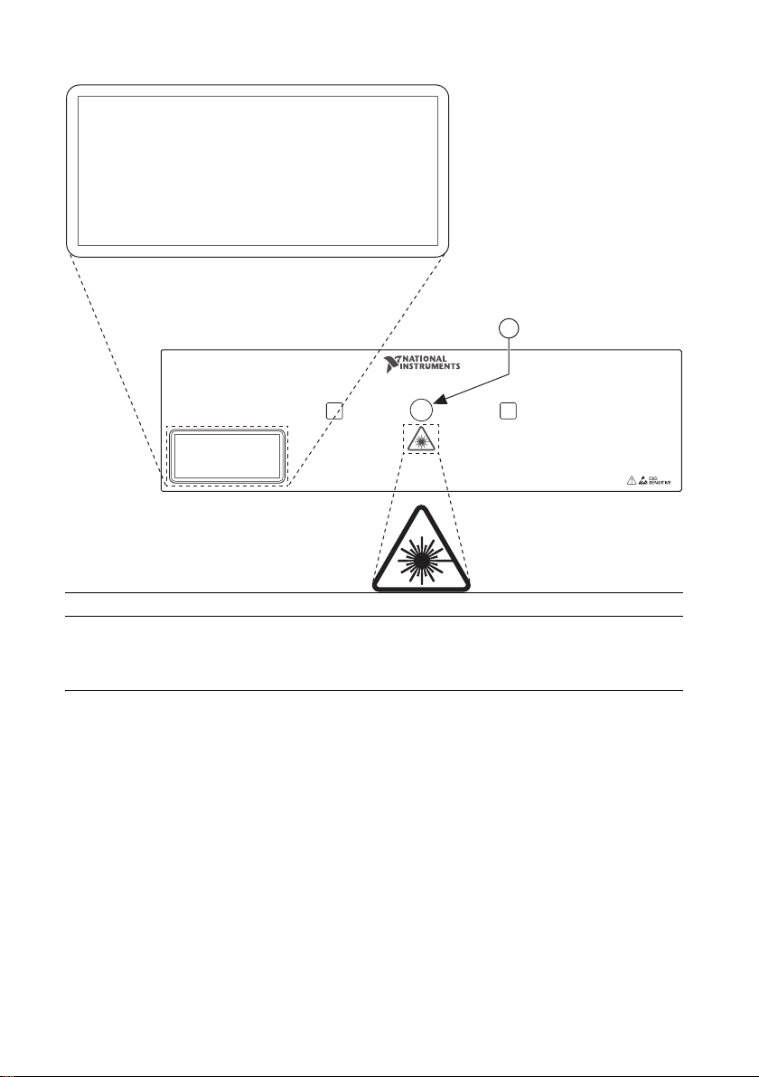
1 Laser Aperture
LASER RADIATION
DO NOT STARE INTO BEAM
CLASS 2 LASER PRODUCT
IEC 60825-1:2007
MAX OUTPUT: 1 mW, WAVELENGTH: 650-660 nm
DURATION: CONTINUOUS
COMPLIES WITH 21 CFR 1040.10 AND 1040.11 EXCEPT FOR
DEVIATIONS PURSUANT TO LASER NOTICE NO. 50,
DATED JUNE 24, 2007
RX
NI mmRH-3608
76
–
81 GHz Bistatic mmWave Transceiver
TX
LASER RADIATION
DO NOT STARE INTO BEAM
CLASS 2 LASER PRODUCT
IEC 60825-1:2007
MAX OUTPUT: 1 mW, WAVELENGTH: 650-660 nm
DURATION: CONTINUOUS
COMPLIES WITH 21 CFR 1040.10 AND 1040.11 EXCEPT FOR
DEVIATIONS PURSUANT TO LASER NOTICE NO. 50,
DATED JUNE 24, 2007
1
Table of contents
Popular Radar manuals by other brands

Endress+Hauser
Endress+Hauser Levelflex FMP55 operating instructions

Endress+Hauser
Endress+Hauser Levelflex FMP53 operating instructions

Siemens
Siemens SITRANS LG250 operating instructions

HYDROLOGICAL SERVICES
HYDROLOGICAL SERVICES HYC 230 manual

K40 ELECTRONICS
K40 ELECTRONICS Platinum 100 owner's manual

Furuno
Furuno FAR-3230S-BB installation manual