nicai systems NIBO burger Instructions for use
NIBO
burger – Robot Kit
Construction manual
version 2015/09/08
Construction manual - Robot kit NIBO burger 08.09.2015
Safety instructions
For construction and operation of the robot please consider the follo ing
safety instructions:
•he robot kit NIBO burger is designed for learning, teaching and
experimental purposes only. he company does not accept any liability for
other uses of the programming adapter. Any other use is at the users own
risk.
•No machines must be attached to the robot. In particular the operation with
devices on main voltage is forbidden.
•he robot must not be operated without supervision. When not in use the
robot is to be separated from the power supply.
•he robot must be operated with stabilized DC voltage by 4,8 V. In particular
the robot must be operated ith rechargeable batteries (1,2V) only and
never with normal batteries (1,5V).
•We take no responsibility for data loss of an attached computer.
•he robot must be used indoors only. In particular the usage of the robot is
expressly forbidden on public roadways!
•For a usage deviating from these guidelines no warranty and no
accountability are assumed, the operation is at your own risk!
For soldering please consider follo ing points:
•Always work with extreme caution with the soldering iron!
•Inappropriate operation can lead to severe burns or cause fires.
•Never place the hot soldering iron on the table or on other surfaces.
•Never leave the soldering iron switched on unsupervised.
•Please consider the possible emission of poisonous fumes when soldering.
Ensure there is sufficient ventilation and wash your hands thoroughly after
work.
•Keep the soldering iron away from children!
•Please consider the safety instructions of the soldering iron manufacturer!
•Pay attention to a correct soldering tip temperature: High temperatures
(400°C) may damage the tip, but also allow a short soldering time. Low
temperatures (320°C) will increase the soldering time. his may damage the
electronic components.
http://nibo.nicai-systems.de 2

Construction manual - Robot kit NIBO burger 08.09.2015
Table of contents
1 Introduction and overview.............................................................................5
1.1 Features.................................................................................................8
1.2 Motors....................................................................................................9
1.2.1 Odometry........................................................................................9
1.2.2 Motor bridge..................................................................................10
1.3 Sensors................................................................................................10
1.3.1 IR sensor bricks............................................................................10
1.3.2 Colour sensor bricks.....................................................................11
1.4 USB interface.......................................................................................13
1.5 Interfaces / Extension ports.................................................................13
1.6 Other hardware components...............................................................14
1.6.1 Free programmable Coding-LEDs................................................14
1.6.2 Function LEDs..............................................................................15
1.6.3 Voltage switch / Charging.............................................................15
2 Assembling of the robot...............................................................................16
2.1 Necessary tools....................................................................................16
2.2 Soldering..............................................................................................17
2.3 Placing components onto the circuit boards........................................20
2.3.1 Preparing operations....................................................................26
2.3.1.1 Overview of the optoelectronic parts.....................................26
2.3.1.2 Seperation of pin header strips.............................................27
2.3.2 Assembly of the sensor bricks......................................................29
2.3.2.1 Placing components onto the bottom sides..........................29
2.3.2.2 Placing components onto the top sides................................30
2.3.3 Component placement of boards and ...................................36
2.3.4 Component placement of boards and ...................................39
2.3.5 Component placement of boards and ...................................42
2.3.5.1 Resistors................................................................................42
2.3.5.2 Zener-/Schottky-Diodes.........................................................45
2.3.5.3 Silizium-Diodes......................................................................45
2.3.6 Ceramic multilayer capacitors.......................................................46
2.3.7 Ceramic plate capacitors..............................................................46
2.3.8 Crystal...........................................................................................46
2.3.8.1 IC-Sockets.............................................................................47
2.3.8.2 Voltage controller IC..............................................................47
2.3.9 NPN Bipolar-transistors................................................................48
2.3.9.1 PNP Bipolar-transistors.........................................................48
2.3.9.2 White leds..............................................................................48
2.3.9.3 Red leds.................................................................................49
2.3.9.4 Blue leds................................................................................49
2.3.9.5 Jumper 2-pole........................................................................50
http://nibo.nicai-systems.de 3

Construction manual - Robot kit NIBO burger 08.09.2015
2.3.9.6 Jumper 3-pole........................................................................50
2.3.9.7 Button....................................................................................50
2.3.9.8 Switch....................................................................................51
2.3.10 Electrolytic capacitors.................................................................51
2.3.10.1 Straight sockets – 5 contacts..............................................51
2.3.10.2 Right-angle sockets – 5 contacts........................................52
2.3.11 Battery packs..............................................................................54
2.3.11.1 Straight 5-pin headers.........................................................57
2.3.11.2 USB socket..........................................................................58
2.4 Visual inspection of the circuit board...................................................63
2.5 Assembling of the modules..................................................................64
2.5.1 Preparation operations.................................................................64
2.5.2 Assembling of the engine section / transmission unit...................67
2.5.3 Mounting the polyamid pin............................................................74
2.5.4 Attaching the wheels.....................................................................75
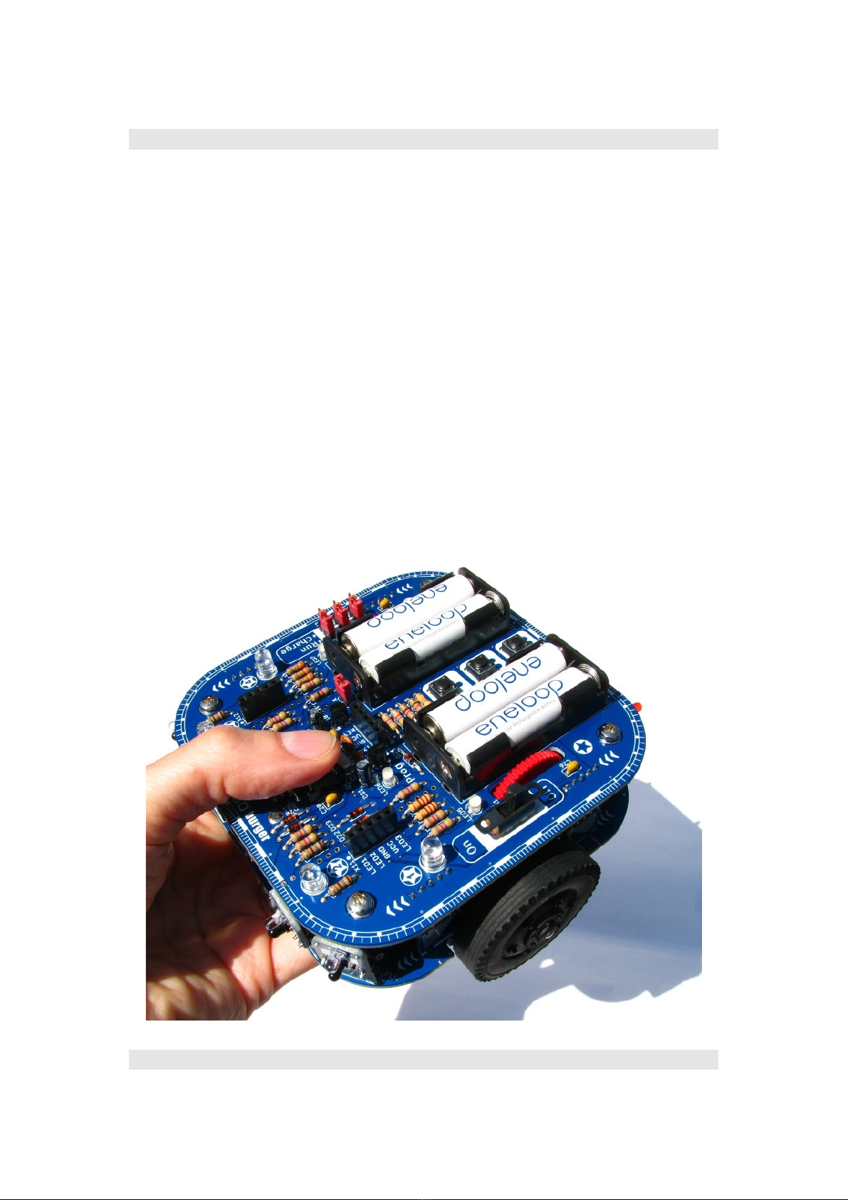
2.5.5 Insertion of the ICs........................................................................76
2.5.6 Assembling of the second layer....................................................77
3 Preparation for operation.............................................................................79
3.1 Part I – Coding-LEDs & buttons...........................................................79
3.2 Part II – Sensor bricks..........................................................................80
3.3 Part III – Motors & odometry sensors..................................................81
3.4 Part IV – Calibration of the sensors.....................................................83
3.5 Installation of the NiboRoboLib............................................................84
3.6 Programming........................................................................................85
3.6.1 NIBO burger Coding utorial (german).........................................85
3.6.2 Online-Compiler – Roboter.CC.....................................................86
3.6.3 NIBO burger ARDUINO utorial (german)....................................88
3.7 Charging the rechargeable batteries by USB......................................89
3.8 25:1 transmission ratio setting.............................................................90
3.9 Additional information...........................................................................92
4 Appendix......................................................................................................93
4.1 Resistor colour codes...........................................................................93
4.2 H parts list........................................................................................94
5 Links............................................................................................................96
http://nibo.nicai-systems.de 4
Construction manual - Robot kit NIBO burger 08.09.2015
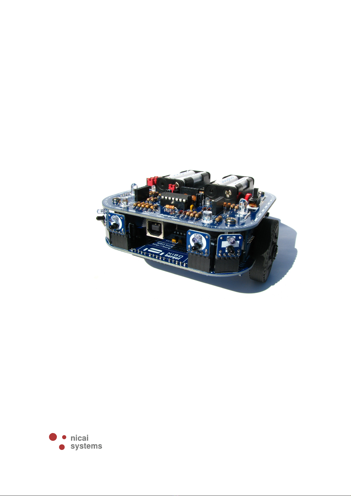
1 Introduction and overvie
he NIBO burger robot kit is a free programmable autonomous robot with
9 sensors. He is able to react stand-alone on his environment.
NIBO burger has an Atmel A mega16 AVR main controller and several
sensors to percept his surroundings. An integrated USB programmer also
acts as charger for the rechargeable batteries.
On the upper board there is an integrated slot for ARDUINO shields.
he variable sensor system contains 7 sensor bricks, which can be
plugged into 10 sensor slots. 3 colour sensor bricks enable the robot to
detect different colours. With 4 IR sensor bricks it is possible to detect
different objects contact-free.
here are two possible versions to assemble the transmission unit: the 25:1
gear transmission ratio allows high speed driving, the 125:1 gear
transmission ratio allows precise driving.
http://nibo.nicai-systems.de 5

Construction manual - Robot kit NIBO burger 08.09.2015
Colour sensor bricks:
IR sensor bricks:
A construction manual with many illustrations explains the assembly and the
necessary soldering step by step. In order to enable a quick and motivating
introduction to the fields robotics, programming and control engineering the
sensors are comfortable to program and to control.
http://nibo.nicai-systems.de 6
Construction manual - Robot kit NIBO burger 08.09.2015
he whole thing is completed by the NiboRoboLib which provides all
important basic functions and a programming tutorial in C for the first steps.
After assembling you can directly start with own programming.
All electronic parts are placed amply dimensioned on the circuit board and so
the robot is quite easy to solder.
http://nibo.nicai-systems.de 7

Construction manual - Robot kit NIBO burger 08.09.2015
1.1 Features
Technical data:
•Dimensions: (L x W x H) 108 x 126 x 58 mm
•Weight: 295g (with rechargeable batteries)
•Power supply: 4 AAA Micro rechargeable batteries with 1,2 V each
•Voltages: 4,8 V and 3,3V (stabilised)
•Dimensions of main circuit board: 108 x 108 mm
Equipment:
•A mega16 (16 kB Flash, 1 kB SRAM, 15 MHz)
•A tiny44 to control the integrated USB-programmer
•USB-programmer which also provides as battery charger for the
rechargeable batteries
•4 coding LEDs for own functions
•3 status LEDs
•3 colour sensor bricks
•4 IR-sensor bricks
•10 sensor slots for the sensor bricks
•3 free programmable push buttons
•2 odometry sensors
•Powered by two motors with 125:1 transmission (convertible to 25:1)
•Jumper to deactivate motor control – Anti move function
•3 extension ports, each with 3 bits (I²C, UAR ) for own
ideas/experiments
•Open source library
•Footprint for ARDUINO shields
http://nibo.nicai-systems.de 8

Construction manual - Robot kit NIBO burger 08.09.2015
Applications:
•Following lines
•Controlled proceed tangent route
•Contact-free detection of obstacles
•Autonomous performance
•Determination of different flooring
•Colour detection
•Barcode detection
•Following walls
Features:
•Main CPU with 16 kByte flash-memory
•Programmable in C, C++ and Java (GNU gcc and nanoVM)
1.2 Motors
he robot is driven by two motors with 125:1 transmission (respectively 25:1
transmission). he motors are driven by a H-bridge with a 14,7 kHz PWM-
signal. he PWM-signal can be regulated by odometry-sensors, thus it is
possible to drive with constant speed.
1.2.1 Odometry
he direction of rotation and the speed of the wheels is measured by two
photo-transistors and two IR-LEDs on the red gearwheels of the transmission.
he speed is directly proportional to the frequency of the signal.
http://nibo.nicai-systems.de 9
Construction manual - Robot kit NIBO burger 08.09.2015
1.2.2 Motor bridge
he motor bridge is needed for current amplification and for voltage regulation
of the microcontroller signals. he motor is controlled by one of three possible
signal-combinations from the H-bridge: high/low (forward), low/high
(backwards), high/high (short-circuit). he short-circuit operating (freewheel)
is for better utilization of energy with PWM-control, since electricity does not
have to flow against the supply voltage in this case. Additionally the freewheel
stabilizes the torque for lower values.
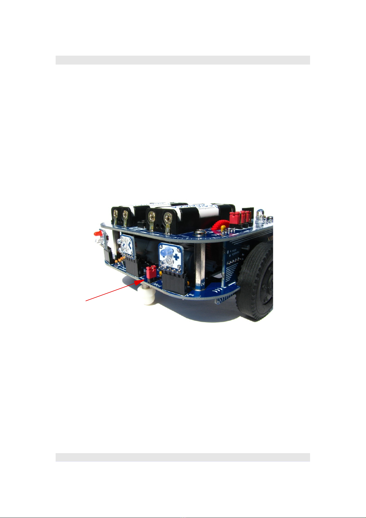
It is possible to deactivate the motor bridge by removing the jumper J4
(Mot) for test cases.
1.3 Sensors
he robot is able to learn and to react on environmental conditions by its
sensors. he following subsections describe the sensors in detail:
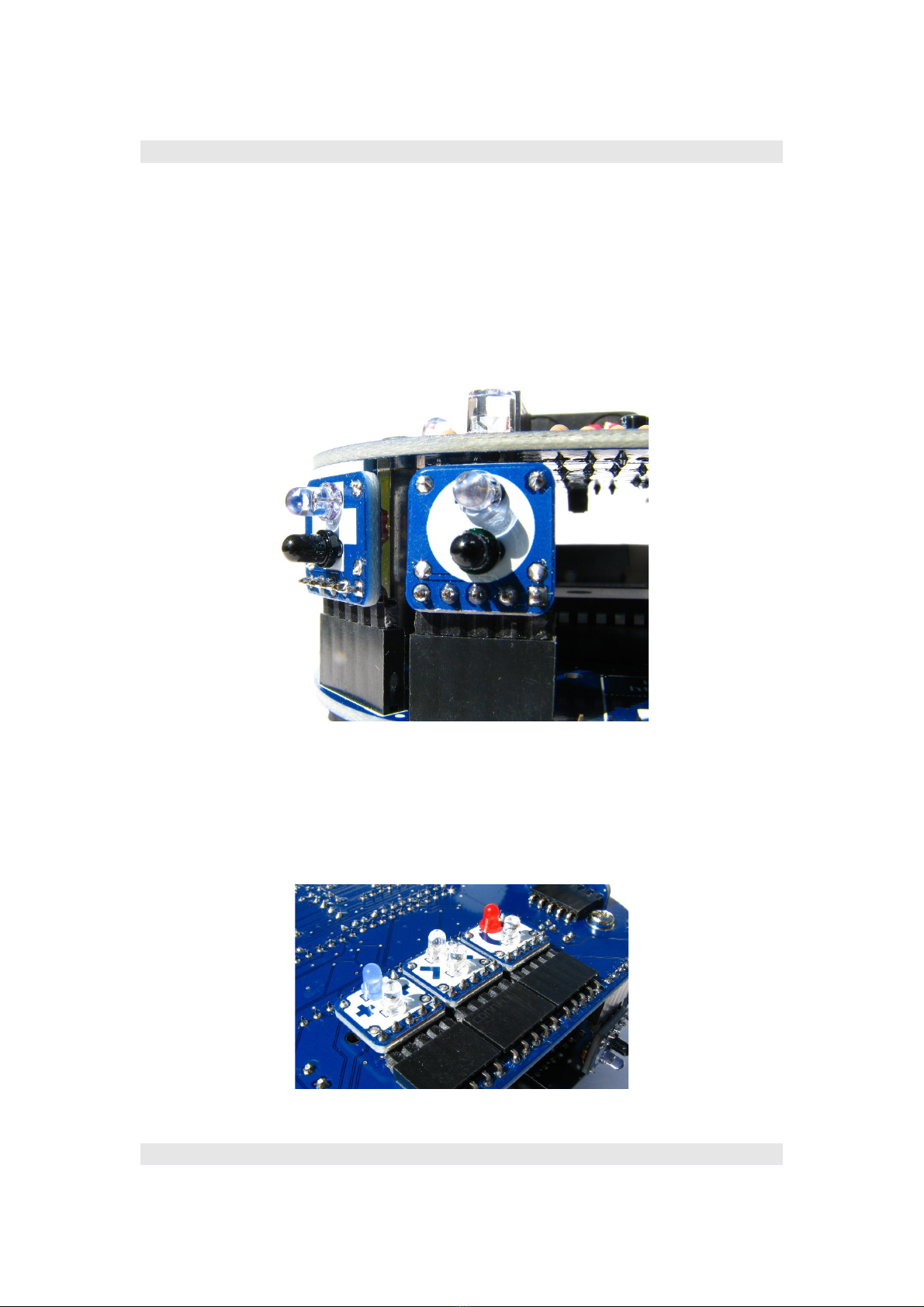
1.3.1 IR sensor bricks
he robot has four IR sensor bricks to detect objects / obstacles contact-free.
Each sensor brick consists one IR phototransistor and one IR led. So the
reflection factor can be measured and interpreted. o avoid the influence of
http://nibo.nicai-systems.de 10
J4 - motor-jumper
Construction manual - Robot kit NIBO burger 08.09.2015
diffused light it is necessary to use a modulation method. his method is
already implemented in the NiboRoboLib.
With the variable sensor system with 10 sensor slots you can test different
setups: For example it is possible to plug all 4 sensors into the front slots, or
you can place 2 sensors on the front and 2 sensors on the back. Another
possibility is to use 3 sensors for analysing the floor.
1.3.2 Colour sensor bricks
NIBO burger has 3 colour sensor bricks (blue, green, red):
http://nibo.nicai-systems.de 11
Construction manual - Robot kit NIBO burger 08.09.2015
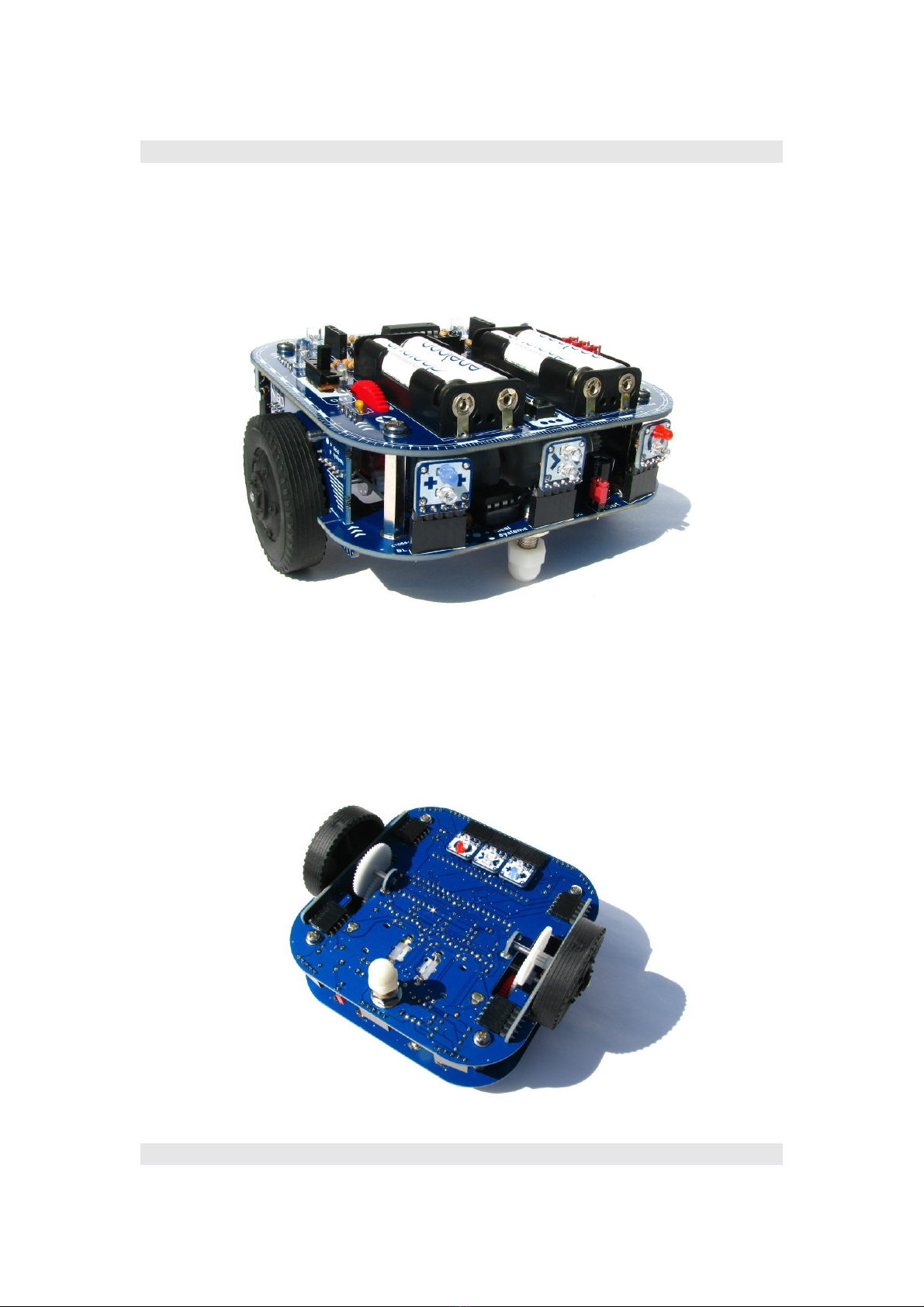
hese sensors can also be plugged into the 10 sensor slots:
For example they can be plugged into the three slots on the back to detect
and to analyse coloured objects:
You can also plug the 3 sensors into the slots at the bottom side of the robot
to analyse coloured floors. his setup is also well suited for following lines.
http://nibo.nicai-systems.de 12
Construction manual - Robot kit NIBO burger 08.09.2015
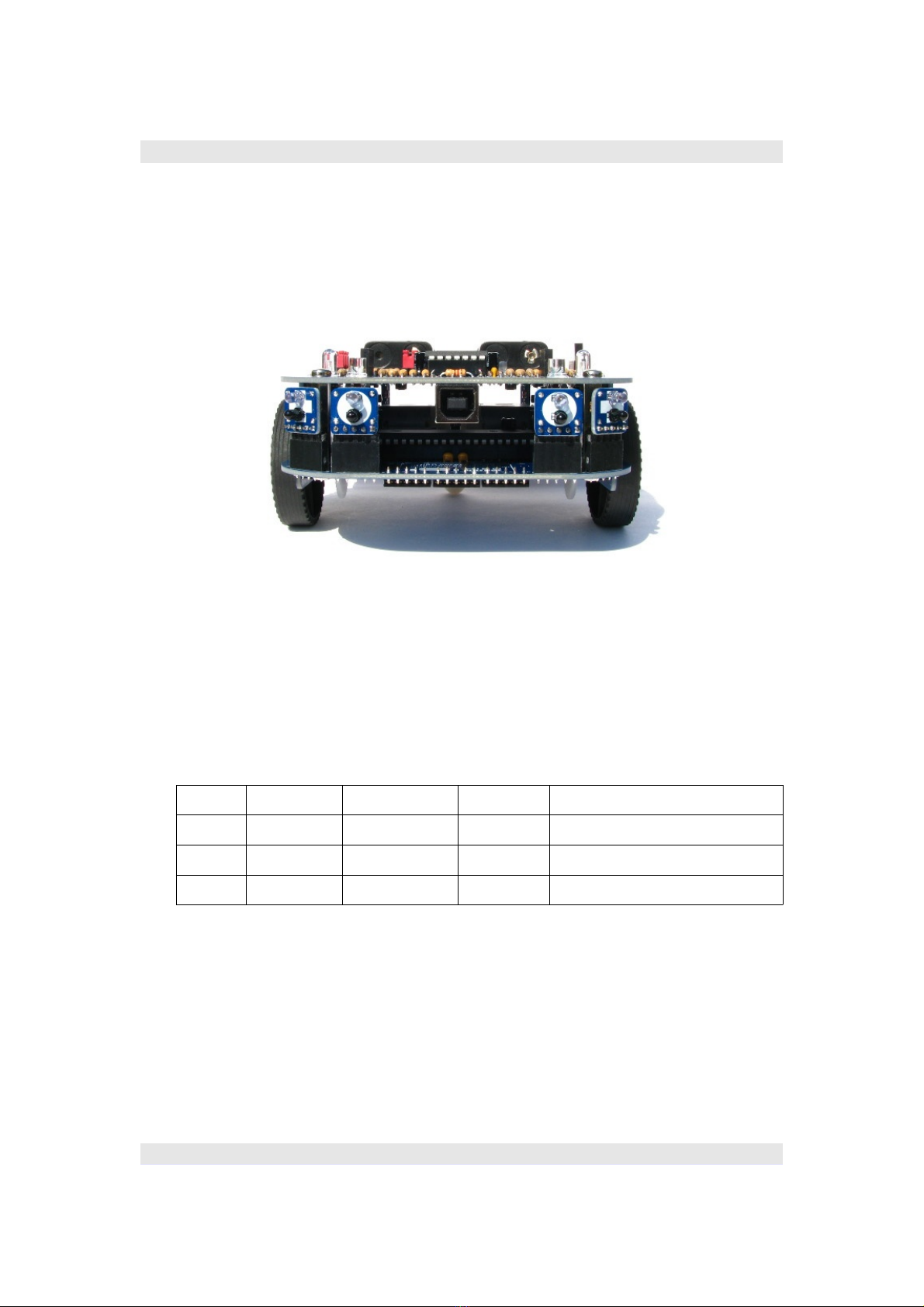
1.4 USB interface
he robot can be connected to a computer by the USB interface. It is possible
to upload new software by this interface. Additionally the rechargeable
batteries can be charged by this interface.
1.5 Interfaces / Extension ports
he NIBO burger has 3 extension ports. Each of these ports has five contacts:
plus, minus and 3 signal bits.
All ports have additional functions:
Port Signal 1 Signal 2 Signal 3 Information
X11 LED1 LED2 LED3 Digital interface
X12 SCL SDA LED4 I²C-interface
X13 RXD XD KEY Serial interface
You can connect own extensions at the port X12 by an I²C-interface.
Extensions with a serial interface can be connected to the port X13.
he signals LED1 – LED4 can be used for own ideas by removing jumper J5
(LED_X).
It is possible to use the KEY signal as an analog input, if none of the buttons
SW1 – SW3 is being pushed.
http://nibo.nicai-systems.de 13

Construction manual - Robot kit NIBO burger 08.09.2015
1.6 Other hard are components
1.6.1 Free programmable Coding-LEDs
he two red LEDs (LED 1 and LED 4) and the two blue LEDs (LED 2 and LED
3) are coding LEDs. hey can be controlled by own programming.
http://nibo.nicai-systems.de 14
X13
X11
X12
Construction manual - Robot kit NIBO burger 08.09.2015
1.6.2 Function LEDs
he small white LEDs show the following functions:
LED 5 Operating mode information: flashes during the robot is online
LED 6 Programming: flashes during the programming process
LED 7 harging information: flashes during the charging process
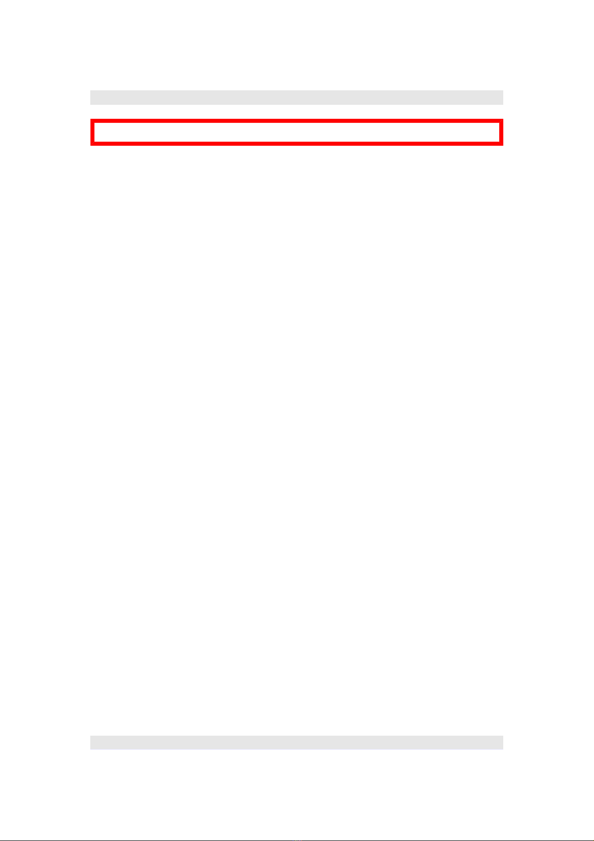
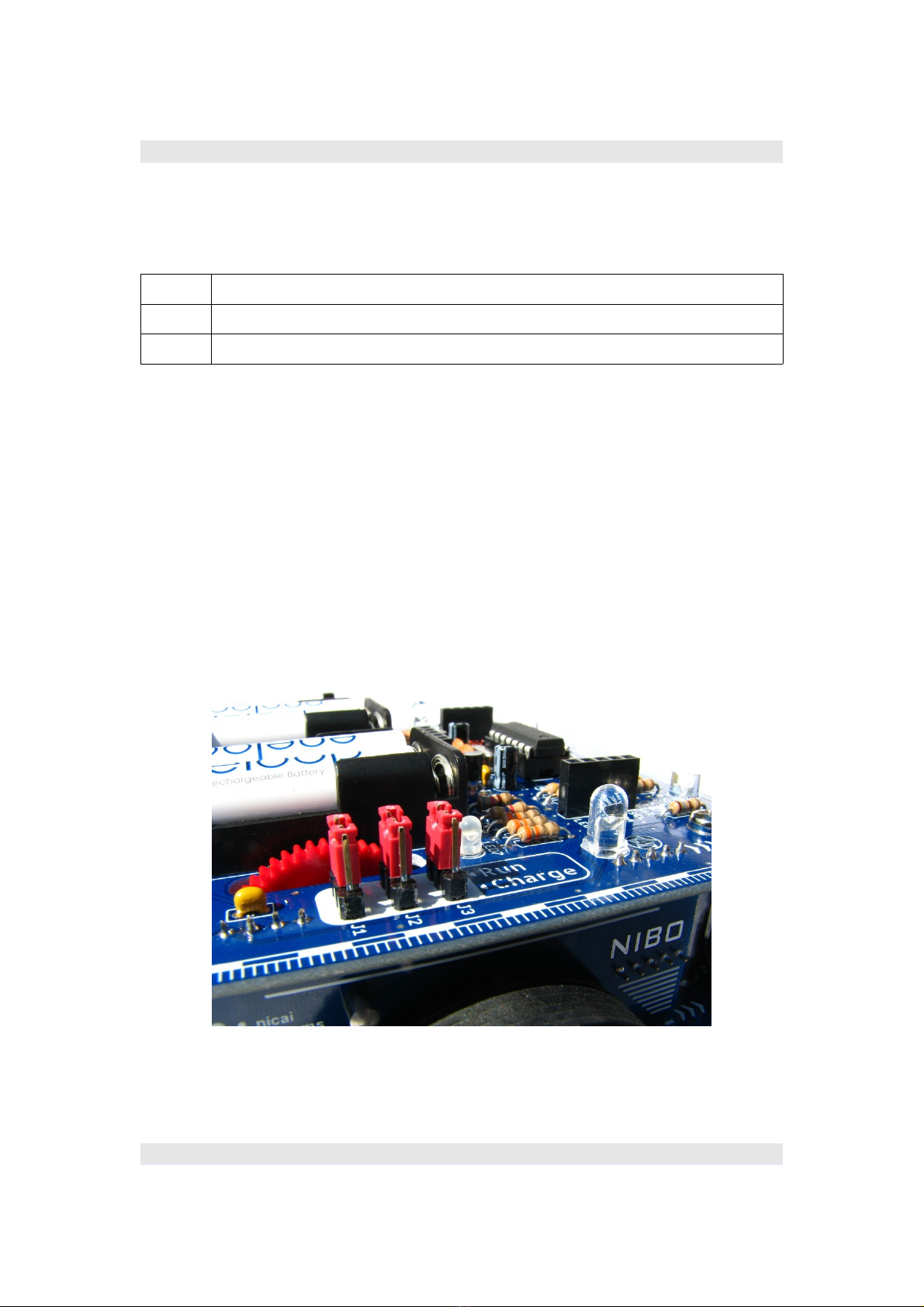
1.6.3 Voltage s itch / Charging
he voltage switch S1 separates the battery voltage from the circuit and
provides the possibility to charge the rechargeable batteries in combination
with the jumpers J1, J2 and J3 (see chapter 3.7).
Normal operation (RUN):
http://nibo.nicai-systems.de 15

Construction manual - Robot kit NIBO burger 08.09.2015
2 Assembling of the robot
Please read the following chapter completely before you begin with the
assembly!
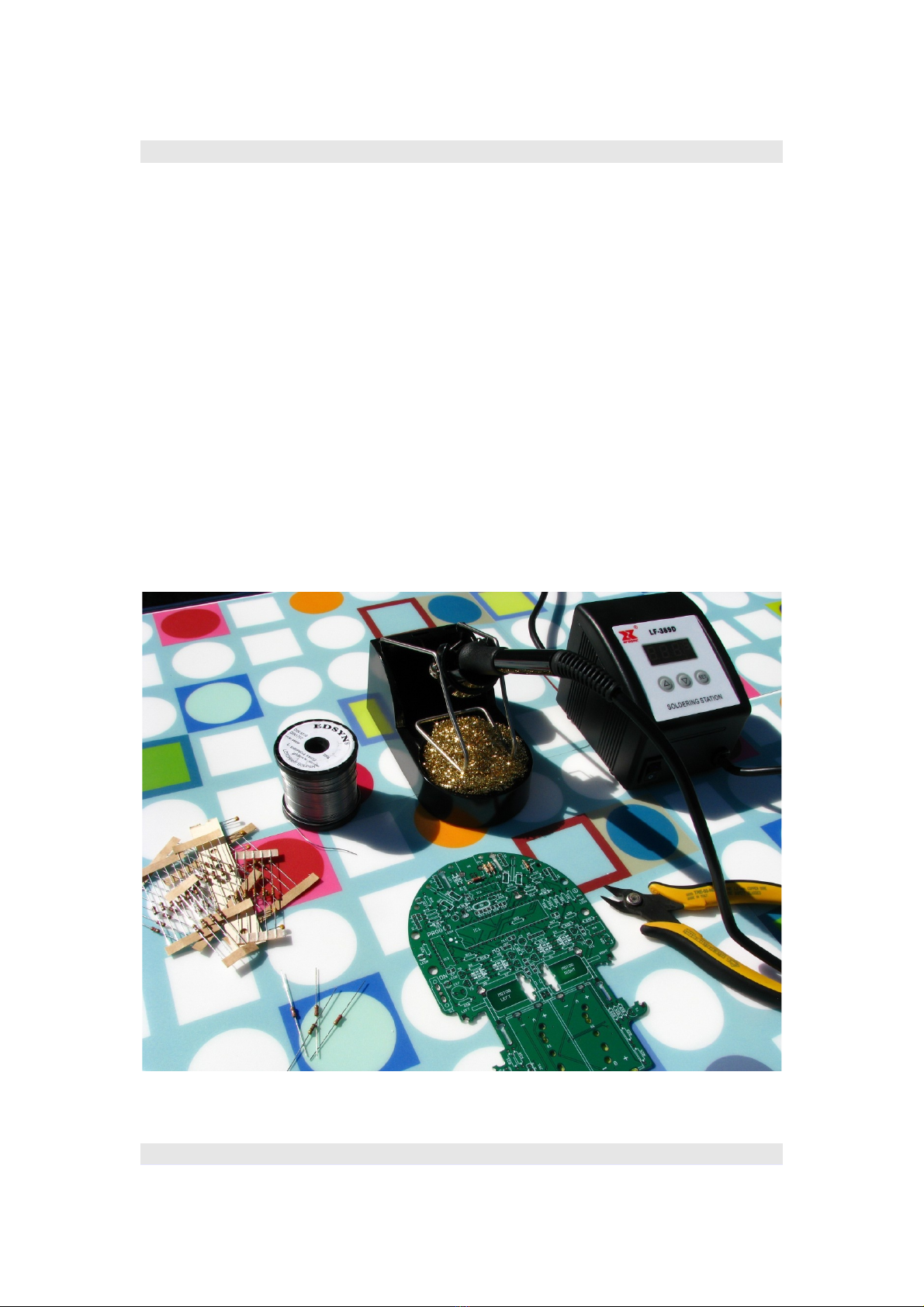
2.1 Necessary tools
You need the following tools for the assembly:
Soldering iron with sponge & electronic solder wire
Electronic cutting pliers
Small recessed head screwdriver
Universal pliers
Small hammer
If there occur problems after the assembly, you can use the following tools:
Soldering remover
Multimeter (with continuity tester)
http://nibo.nicai-systems.de 16
Construction manual - Robot kit NIBO burger 08.09.2015
2.2 Soldering
For soldering you should use a regulated soldering station with at least
50 W and a fine tip.
Tip: he manual of the soldering station should definitely contain the word
“regulated”. A regulated soldering station means, that it “knows” exactly the
temperature of its tip. So it is able to readjust the temperature if its necessary.
It is very helpful to have no temperature drop during soldering!
You should select a temperature of about 370 °C, depending on the soldering
station the temperature can drift up to 400 °C. he best thing is to test it. You
should use flux cored solder wire with a diameter of 0.5 mm. he best for
beginners is to start with lead-containing solder wire (SN60PB40).
http://nibo.nicai-systems.de 17

Construction manual - Robot kit NIBO burger 08.09.2015
Soldering should work like this:
Video „Soldering in 30 seconds“ http://www.nicai.eu/soldering
If it doesn't work as seen in the video, it can be useful
to check the own soldering equipment and/or get someones help.
he soldering time should be limited to a few seconds (not minutes!) for each
pad. Most electrical components react sensitively to high temperature.
For very sensitively components you can do the following:
First you solder 3-5 seconds, if the soldering point isn't good enough yet, you
let the component cool down and afterwards you solder again for 3-5
seconds.
he optical components (LEDs, IR-LEDs and phototransistors) are very
sensitively components.
Procedure:
First of all you have to insert the legs of the electronic part into the soldering
pads of the circuit board. On some parts you have to pay attention to the
polarity. hat means that it is quite important which leg has to be connected
to which pad!
http://nibo.nicai-systems.de 18

Construction manual - Robot kit NIBO burger 08.09.2015
Now you have to heat the soldering pad and the leg simultaneously with
the soldering iron at the bottom side of the board:
hen the tin-solder has to be attached additionally. If everything is well
heated, the tin-solder is melting and the leg of the electronic part gets
connected to the soldering pad:
he finished soldering point should look like this:
he leg of the electronic part has to be fixed at the soldering pad. If it is not
yet fixed, you have to solder again!
Now you can remove the remaining legs with an electronic cutting pliers. he
cutting pliers has to be positioned parallel to the circuit board for not cutting
through some traces:
Finished soldering point:
Hint: Don't breath in the solder smoke and wash your hands after soldering!
http://nibo.nicai-systems.de 19
Construction manual - Robot kit NIBO burger 08.09.2015
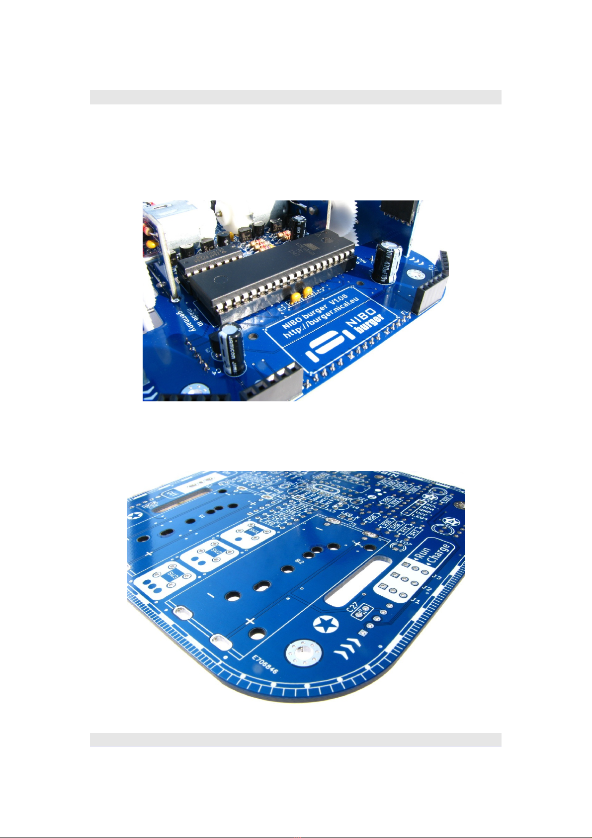
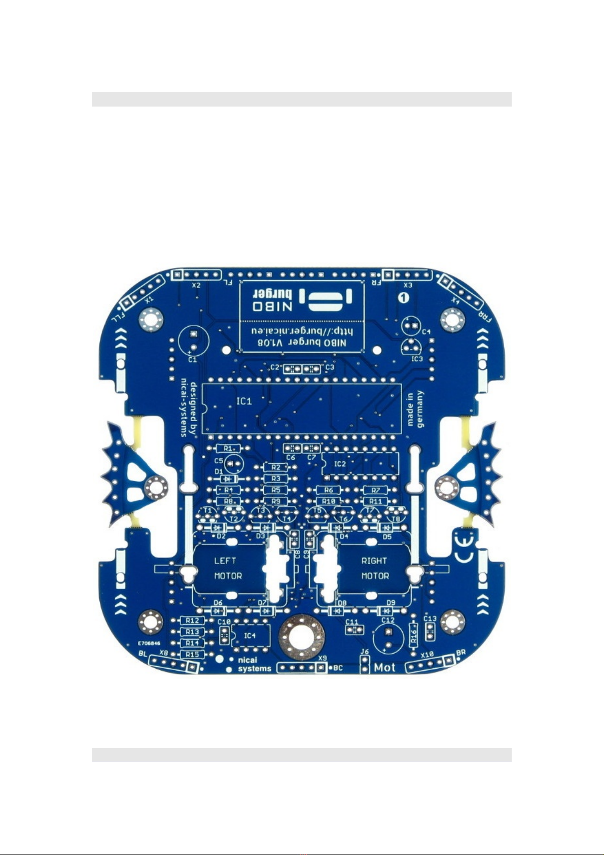
2.3 Placing components onto the circuit boards
his section describes how to place the electrical components onto the circuit
boards. First of all an overview of the plain boards:
Board - first level:
http://nibo.nicai-systems.de 20
Table of contents


