Joy-it JOY-CAR User manual

JOY-CAR
Education robot based on micro:bit
WWW.JOY-IT.NET

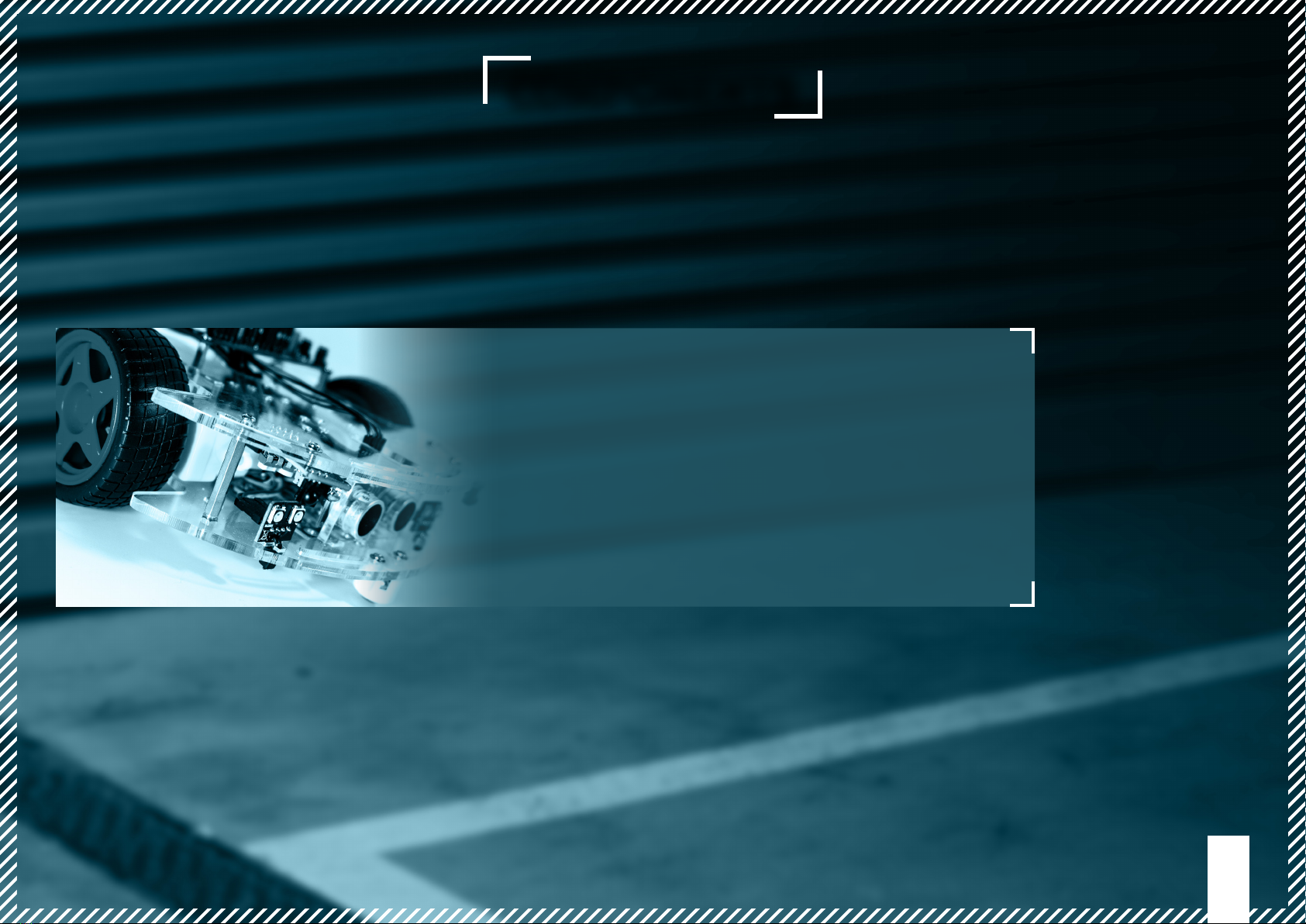
The Joy-Car is a modular built education kit for
Robotics. Itservesforlearningofbuilding partsand
their function inside a whole machine. Learning
is especially easy because of the detailled manual
and the programming. Joy-Car has sensors like
the line-nder or the ultra sonic senor as well as a
programmable RGB-lighting. You can even control
the Joy-Car with the acceleration sensor via a
wireless BT connection by using a second micro:bit
JOY-CAR
4

5
COMPONENTS
Welcome to your own Joy-Car Assembly kit! There is much to discover, but you
won‘t enter this journey alone! In the following chapters, we show you step by
step, how you create your own, ridable project out of this assembly kit.
-
wards, we are ready to start!

CHASSIS
6
BASE
1x
CHASSIS
1x
BATTERY BRACKET A
1x
PARKING
BRACKETS A
4x
PARKING
BRACKETS B
2x
ULTRASONIC
BRACKET
1x
MOTOR BRACKETS
2x
SERVO BRACKET
1x
SPACER
1x
BATTERY BRACKET B
1x
BATTER BRACKET C
1x

ELECTRONICS
7
MAINBOARD
1x
LED BOARD
4x
SPEEDSENSOR
2x
ULTRASONIC-
SENSOR
1x
BATTERY CASE
1x
3-PIN DUPONT-
CABLE SET
7x
4-PIN DUPONT-
CABLE SET
5x
LINETRACKING-
SENSOR
3x
OBSTACLE-SENSOR
2x
SERVOMOTOR
2x
MOTOR
2x
MICRO:BIT
1x
NOT INCLUDED IN EVERY JOY-
CAR SET!

ASSEMBLY
MATERIAL
8
SCREW
4x M2,5 x 5 mm
SCREW
12x M2,5 x 10 mm
SCREW
4x M2,5 x 22 mm
SCREW
6x M3 x 8 mm
SPACER
4x M2,5 x 10 mm
SPACER
4x M3 x 30 mm
BALL CASTER
2x
CABLE TIE
15x
SCREW
5x M3 x 14 mm
WASHER
30x M2,5
NUT
20x M2,5
NUT
15x M3

ASSEMBLY
9
Even though there are many components, modules and cables, we won‘t let
you down. In this chapter, we show you step by step how you will assemble
your Joy-Car.
You will see, it is easier than you might think and you will learn also about
every single part of the Joy-Car!

10
BASE
CHASSIS
WIRING
ULTRASONIC
ALTERNATIVE ASSEMBLY
FINISH
DRIVE TRAIN
ELECTRONICS
BASE ASSEMBLY
First, we assemble the base. Any brackets and spacers, that are necessary for the
following steps, will be mounted now.
ATTENTION! All acrylic parts are laminated with a protection foil. This foil must
be removed before any assembly works.

11
1. MOUNT SPACERS
First, mount the 4 spacers (M3 x 30mm) to the base and secure
them from below with the matching nuts (M3).
2. MOUNT ULTRASONIC BRACKET
Mount the ultrasonic bracket to the base. Secure them from below
with the matching screw (M3 x14 mm) and the matching nut (M3).
ATTENTION! Advanced users can also mount the ultrasonic sensor
moveable together with the servor motor onto the chassis top
part (see for alternative ultrasonic assembly). For beginners, the
following assembly suits the most.

12
4. MOUNT THE BATTERY CASE
Take the battery bracket A and put it on the upper side of the base.
The short end of the battery bracket should point towards the
middle of the base. Place battery bracket B onto the wide side of
the battery bracket A and secure them with the matching screws
(M2.5 x10mm) and nuts (M2.5). The battery bracket C is placed
on the narrow side of the battery bracket A. This also needs to be
secured with the matching screws (M3x 14mm) and nuts (M3).
A
B
C
3. MOUNT BALL CASTERS
Mount the ball casters to the base. For the front, use the screws
from the ball caster. For the back, use the M2,5 x10mm screws.
ATTENTION! Use the spacer for the mounting of the ball caster at
the rear axle.

13
DRIVE TRAIN ASSEMBLY
As next step, we assemble the drive train and mount it on the Joy-Car. The drive
train contains the motors and is therefore responsible for the propulsion of the
Joy-Car.
BASE
CHASSIS
WIRING
ULTRASONIC
ALTERNATIVE ASSEMBLY
FINISH
DRIVE TRAIN
ELECTRONICS

14
1. PRE-ASSEMBLE THE MOTORS
Put both motors into the ducts of the motor brackets and secure
them with the matching screws (M2.5 x22mm) and nuts (M2.5).
Additionally use two washers (M2.5) per screw, one on the screw
head and one on the screw end.
motor.
2. MOUNT THE BRACKET TO THE CHASSIS
Now mount the motor brackets onto the base. Secure them from
below with the matching screw (M3 x14mm) and nut (M3).
INSERT NUT HERE FIRST
THEN INSERT AND TIGHTEN
THE SCREW

15
ELECTRONICS ASSEMBLY
Next, we insert all electronic components into the base. This includes not only the
individual sensors, but also the LED modules which are used as headlights.
BASE
CHASSIS
WIRING
ULTRASONIC
ALTERNATIVE ASSEMBLY
FINISH
DRIVE TRAIN
ELECTRONICS

16
1. FRONT HEADLIGHTS
Insert the WS2812B LED headlight modules into the front of the
base. Secure them with the cable ties. You can simply insert the
cable tie through the hole of the headlights and the hole of the base
and set it tight.
2. REAR HEADLIGHTS
Mount the headlight modules on the rear of the base with the cable
ties.
INSERT CABLE TIE TROUGH HOLE
OF HEADLIGHT AND HOLE OF
BASE AND SET IT TIGHT.

17
3. LINETRACKING-SENSORS
Mount the linetracking-sensors at the bottom side with the
matching screws (M2.5 x10mm) and nuts (M2.5). Use 2 washers per
screw (M2.5).
4. SPEED-SENSORS
Insert the speed-sensors into the bottom side of the base. Secure
them with the matching screws (M2.5 x 10mm) and nuts (M2.5).

18
5. ULTRASONIC-SENSOR
Insert the ultrasonic-sensor into the bracket. If needed, you can
additionally secure it with some glue. The 4 connection pins need
to point upwards.
ATTENTION! If youshould have decided toassemblethe ultrasonic-
sensor on a moveable servo motor at the second step of the base
assembly procedure, then please skip this step.

19
CHASSIS ASSEMBLY
The base is now ready. We will now start with the chassis. This includes, besides
the mainboard bracket, the obstacle sensors.
BASE
CHASSIS
WIRING
ULTRASONIC
ALTERNATIVE ASSEMBLY
FINISH
DRIVE TRAIN
ELECTRONICS

20
2. OBSTACLE-SENSORS
Mount the obstacle-sensors on the bottom side of the chassis with
the matching screws (M2.5 x10mm), washers and nuts (M2.5).
1. ATTACH SPACERS
Attach the 4 spacers (M2.5 x10mm) onto the chassis and secure
them from below with the matching nuts (M2.5).
ATTENTION! Pleasemind that the two highlighted holes arelocated
Table of contents
Other Joy-it Robotics manuals